Loading ...
Loading ...
Loading ...
1. Overview: Location and Function of Parts
00011
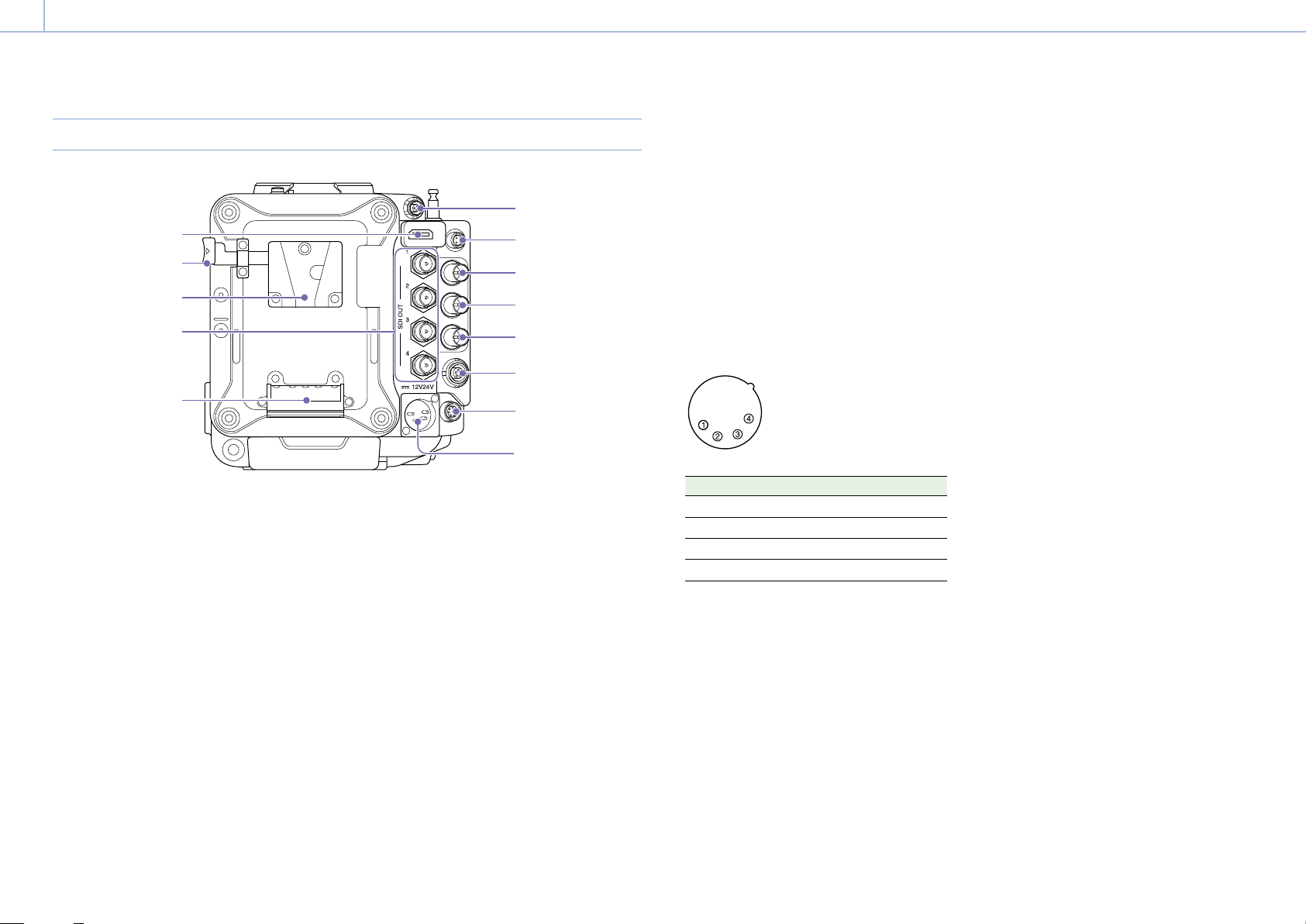
Rear
2
1
3
4
5
6
7
8
9
10
11
12
13
1. 24V OUT connector (DC OUT 24 V, Fischer
3-pin)
24 V DC power supply output connector
(page 90).
The output voltage and maximum output
current of this connector vary depending on
the input voltage to the unit. The maximum
current includes the output current from the
24V OUT connector on the front panel
(page 10).
11 V to 17 V input
Output voltage : 24 V
Maximum output current: 1.0 A
22 V to 32 V input
Output voltage: Same as the input voltage
Maximum output current: 2.0 A
2.
12V OUT connector (DC OUT 12V, Hirose
4-pin)
12 V DC power supply output connector
(page 90).
The output voltage and maximum output
current of this connector vary depending on
the input voltage to the unit.
11 V to 17 V input
Output voltage: Same as the input voltage
Maximum output current: 1.0 A
22 V to 32 V input
Output voltage : 15 V
Maximum output current: 0.8 A
3. MONITOR OUT connector (BNC type)
HD SDI monitor signal output connector
(page 90).
4. GENLOCK (genlock input) connector (BNC
type)
To genlock the unit to an external source or to
lock the timecode of the unit to an external
source, input an external reference signal.
Digital signal and analog signal input are
supported.
Digital signal: 1.5G HDSDI interlaced signal
Analog signal: HD sync, Analog
5. TC IN (timecode input) connector (BNC type)
To lock the timecode of the unit to an external
source, input a reference timecode signal.
6. AUX connector (LEMO 5-pin)
Outputs the timecode signal (page 91).
7. REMOTE (remote control) connector (8-pin)
Connect to a remote control unit or other
external control device.
8. 12V/24V (DC power input) connector
(page 16)
DC power supply input connector for external
power supply to the unit. Supports 12 V and 24
V input voltages.
No. Signal
1 GND
2 NC
3 NC
4 DC IN (11 V to 17 V or 22 V to 32 V)
9. Battery attachment terminal (page 16)
10. SDI OUT 1 to 4 (serial digital output)
connectors (BNC type) (page 90)
11. Battery pack mount (page 16)
12. Battery release lever (page 16)
13. HDMI OUT connector (page 90)
Loading ...
Loading ...
Loading ...