Loading ...
Loading ...
Loading ...
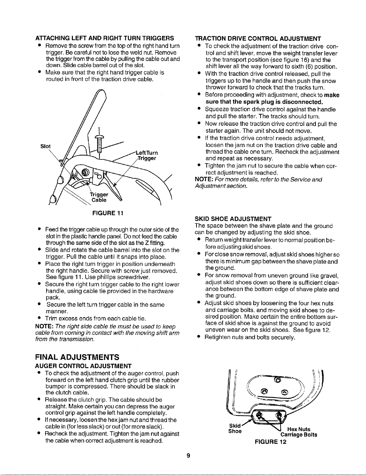
ATTACHINGLEFTANDRIGHTTURNTRIGGERS
• Remove the screw from the top of the right hand turn
trigger. Be careful not to lose the weld nut. Remove
the trigger from the cable by pulling the cable out and
down. Slide cable barrel out of the slot.
• Make sure that the right hand trigger cable is
routed in front of the traction drive cable.
I
Slot
TRACTION DRIVE CONTROL ADJUSTMENT
• To check the adjustment of the traction drive con-
trol and shift lever, move the weight transfer lever
to the transport position (see figure 16) and the
shift lever all the way forward to sixth (6) position.
• With the traction drive control released, pull the
triggers up to the handle and then push the snow
thrower forward to check that the tracks turn.
• Before proceeding with adjustment, checkto make
sure that the spark plug is disconnected.
• Squeeze traction drive control against the handle
and pull the starter. The tracks should turn.
• Now release the traction drive control and pull the
starter again. The unit should not move.
• If the traction drive control needs adjustment,
loosen the jam nut on the traction drive cable and
thread the cable one turn. Recheck the adjustment
and repeat as necessary.
• Tighten the jam nut to secure the cable when cor-
rect adjustment is reached.
NOTE: For more details, refer to the Service and
Adjustment section.
FIGURE 11
• Feed the triggercable up throughthe outer side of the
slot in the plastic handle panel. Do not feed the cable
through the same side ofthe slot as the Z fitting.
• Slide and rotate the cable barrel into the slot on the
trigger. Pull the cable until it snaps into place.
• Place the right turn trigger in position underneath
the right handle. Secure with screw just removed.
See figure 11. Use phillips screwdriver.
• Secure the right turn trigger cable to the right lower
handle, using cable tie provided in the hardware
pack.
• Secure the left turn trigger cable in the same
manner.
• Trim excess ends from each cable tie.
NOTE: The right side cable tie must be used to keep
cable from coming in contact with the moving shift arm
from the transmission.
SKID SHOE ADJUSTMENT
The space between the shave plate and the ground
can be changed by adjusting the skid shoe.
• Return weight transfer lever to normal position be-
fore adjusting skid shoes.
• For close snow removal, adjust skid shoes higher so
there is minimum gap between the shave plate and
the ground.
• For snow removal from uneven ground like gravel,
adjust skid shoes down so there is sufficient clear-
ance between the bottom edge of shave plate and
the ground.
• Adjust skid shoes by loosening the four hex nuts
and carriage bolts, and moving skid shoes to de-
sired position. Make certain the entire bottom sur-
face of skid shoe is against the ground to avoid
uneven wear on the skid shoes. See figure 12.
• Retighten nuts and bolts securely.
FINAL ADJUSTMENTS
AUGER CONTROL ADJUSTMENT
• To check the adjustment of the auger control, push
forward on the left hand clutch grip until the rubber
bumper is compressed. There should be slack in
the clutch cable.
• Release the clutch grip. The cable should be
straight. Make certain you can depress the auger
control grip against the left handle completely.
• If necessary, loosen the hex jam nut and thread the
cable in (for less slack) or out (for more slack).
• Recheck the adjustment. Tighten the jam nut against
the cable when correct adjustment is reached.
Skid
Shoe
Hex Nuts
Carriage Bolts
FIGURE 12
Loading ...
Loading ...
Loading ...