Loading ...
Loading ...
Loading ...
IMPORTANT: This engine has been shipped without
gasoline or oil. After assembly, see operation section
of this manual for proper fuel and engine oil recom-
mendations.
NOTE: To determine right and left hand sides of your
snow thrower, stand behind it in the normal operating
position.
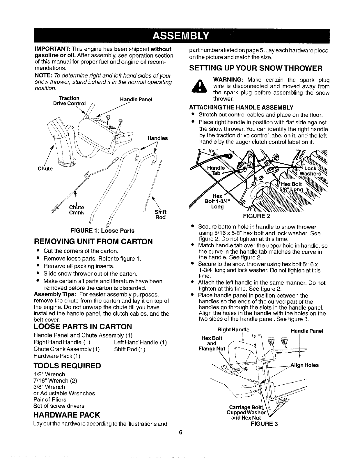
Traction Handle Panel
Handles
Crank
//
// //
/ / ////
/!
Rod
FIGURE 1: Loose Parts
REMOVING UNIT FROM CARTON
• Cut the corners of the carton.
• Remove loose parts. Refer to figure 1.
• Remove all packing inserts.
• Slide snow thrower out of the carton.
• Make certain all parts and literature have been
removed before the carton is discarded.
AssemblyTips: For easier assembly purposes,
remove the chute from the carton and lay it on top of
the engine. Do not unwrap the chute till you have
installed the handle panel, the clutch cables, and the
belt cover.
LOOSE PARTS IN CARTON
Handle Panel and Chute Assembly (1)
Right Hand Handle (1) Left Hand Handle (1)
Chute Crank Assembly (1) Shift Rod (1)
Hardware Pack (1)
TOOLS REQUIRED
1/2" Wrench
7/16" Wrench (2)
3/8" Wrench
or Adjustable Wrenches
Pair of Pliers
Set of screw drivers
HARDWARE PACK
Lay out the hardware according to the illustrationsand
part numbers listed on page 5. Lay each hardware piece
on the picture and match the size.
SETTING UPYOUR SNOWTHROWER
WARNING: Make certain the spark plug
wire is disconnected and moved away from
the spark plug before assembling the snow
thrower.
ATTACHING THE HANDLE ASSEMBLY
• Stretch out control cables and place on the floor.
• Place right handle in position with flat side against
the snow thrower. You can identify the right handle
by the traction drive control label on it, and the left
handle by the auger clutch control label on it.
Bolt 1-3/4"
Long
FIGURE 2
• Secure bottom hole in handle to snow thrower
using 5/16 x 5/8" hex bolt and lock washer. See
figure 2. Do not tighten at this time.
• Match handle tab over the upper hole in handle, so
the curve in the handle tab matches the curve in
the handle. See figure 2.
• Secure to the snow thrower using hex bolt 5/16 x
1-3/4" long and lock washer. Do not tighten atthis
time.
• Attach the left handle in the same manner. Do not
tighten at this time. See figure 2.
• Place handle panel in position between the
handles so the ends of the curved part of the
handles go through the slots inthe handle panel.
Align the holes in the handle with the holes on the
two sides of the handle panel. See figure 3.
RightHandle Handle Panel
.exOo,,on°Flange I_ .....
Carriage Boltl_
Cupped Washer
and Hex Nut
FIGURE 3
Loading ...
Loading ...
Loading ...