Loading ...
Loading ...
Loading ...
GEAR CASE
• The gear case is lubricated with grease at the
factory and does not require checking. If
disassembled for any reason, lubricate with 2
ounces of Shell Alvania grease.
BEARINGS
• Lubricate the auger bearings, wheel bearings and
the bearings on the side of the frame once a
season with light oil.
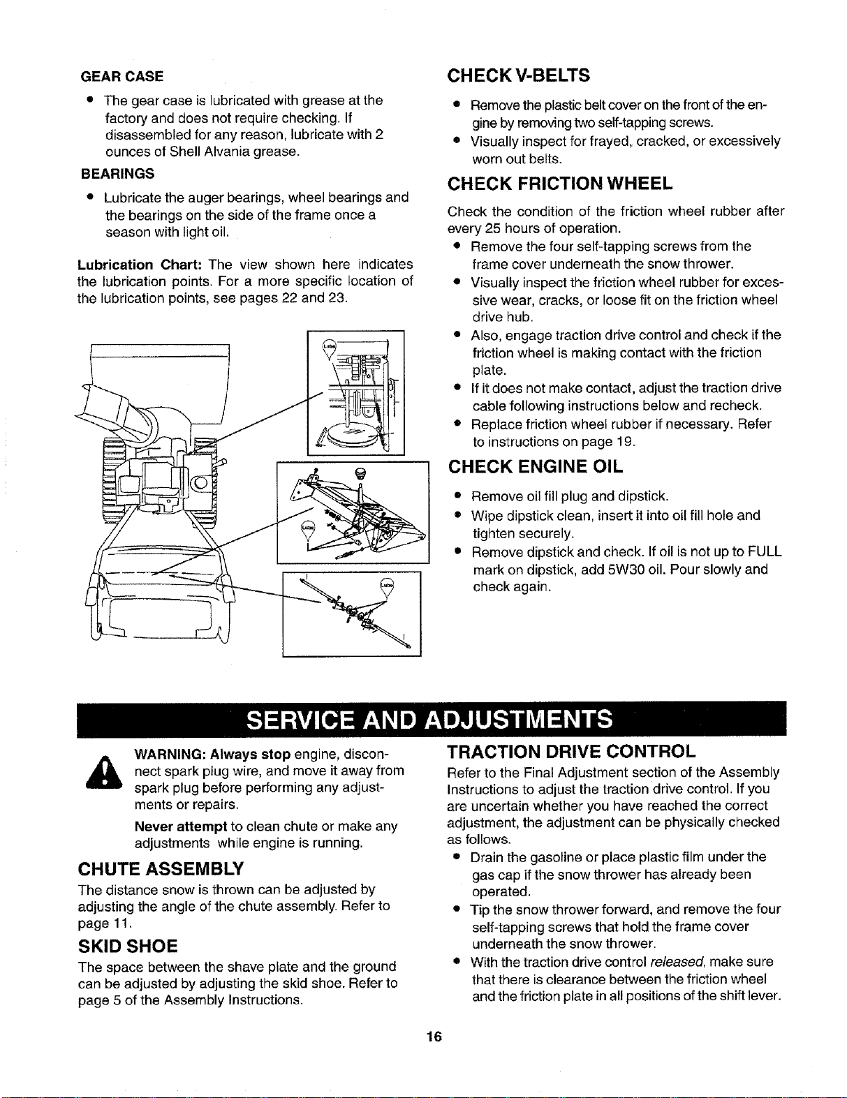
Lubrication Chart: The view shown here indicates
the lubrication points. For a more specific location of
the lubrication points, see pages 22 and 23.
CHECK V-BELTS
• Remove the plastic belt cover on the front of the en-
gine by removing two self-tapping screws.
• Visually inspect for frayed, cracked, or excessively
worn out belts.
CHECK FRICTION WHEEL
Check the condition of the friction wheel rubber after
every 25 hours of operation.
• Remove the four self-tapping screws from the
frame cover underneath the snow thrower.
• Visually inspect the friction wheel rubber for exces-
sive wear, cracks, or loose fit on the friction wheel
drive hub.
• Also, engage traction drive control and check if the
friction wheel is making contact with the friction
plate.
• If it does not make contact, adjust the traction drive
cable following instructions below and recheck.
• Replace friction wheel rubber if necessary. Refer
to instructions on page 19.
CHECK ENGINE OIL
• Remove oil fill plug and dipstick.
• Wipe dipstick clean, insert it into oil fill hole and
tighten securely.
• Remove dipstick and check. Ifoil is not up to FULL
mark on dipstick, add 5W30 oil. Pour slowly and
check again.
WARNING: Always stop engine, discon-
nect wire, and move it from
spark plug away
spark plug before performing any adjust-
ments or repairs.
Never attempt to clean chute or make any
adjustments while engine is running.
CHUTE ASSEMBLY
The distance snow is thrown can be adjusted by
adjusting the angle of the chute assembly. Refer to
page 11.
SKID SHOE
The space between the shave plate and the ground
can be adjusted by adjusting the skid shoe. Refer to
page 5 of the Assembly Instructions.
TRACTION DRIVE CONTROL
Refer to the Final Adjustment section of the Assembly
Instructions to adjust the traction drive control. If you
are uncertain whether you have reached the correct
adjustment, the adjustment can be physically checked
as follows.
• Drain the gasoline or place plastic film under the
gas cap if the snow thrower has already been
operated.
• Tip the snow thrower forward, and remove the four
self-tapping screws that hold the frame cover
underneath the snow thrower.
• With the traction drive control released, make sure
that there is clearance between the friction wheel
and the friction plate in all positions of the shift lever.
16
Loading ...
Loading ...
Loading ...