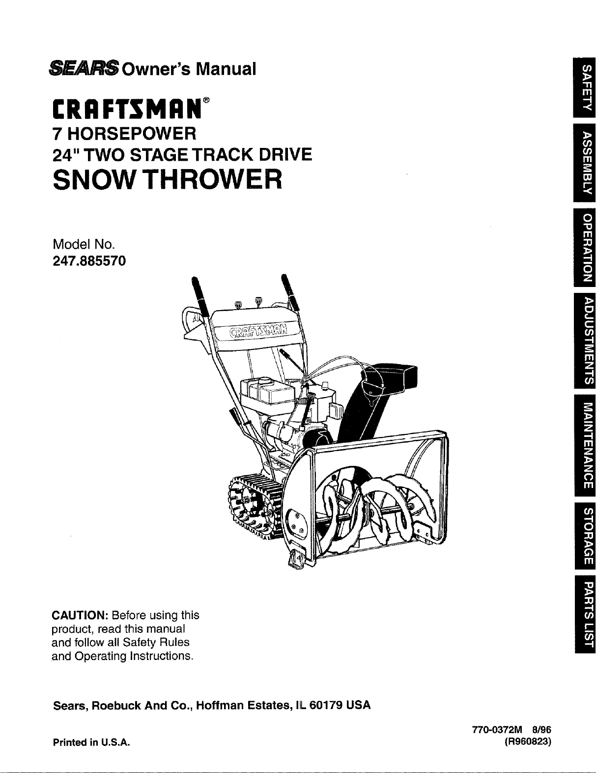
8_ Owner's Manual
CRAFTSMAN°
7 HORSEPOWER
24" TWO STAGE TRACK DRIVE
SNOW THROWER
Model No.
247.885570
/
/
m
CAUTION: Before using this
product, read this manual
and follow all Safety Rules
and Operating Instructions.
Sears, Roebuck And Co., Hoffman Estates, IL 60179 USA
770-0372M 8/96
Printed in U.S.A. (R960823)
Warranty ..................................................................... 2
Safe Operation ........................................................... 3
Hardware Pack ........................................................... 5
Assembly .................................................................... 6
Operation .................................................................. 10
Maintenance ............................................................. 15
Service and Adjustments ......................................... 16
Off-Season Storage ................................................. 20
Trouble Shooting ...................................................... 21
Repair Parts ............................................................. 22
TWO YEAR LIMITED WARRANTY ON CRAFTSMAN SNOW THROWER
For two years from the date of purchase, when this Craftsman Snow Thrower is maintained, lubricated and tuned
up according to the instructions in the owner's manual, Sears will repair, free of charge, any defect in material and
workmanship.
If this Craftsman snow thrower is used for commercial or rental purposes, this warranty applies for only 30 days
from the date of purchase.
This warranty does not cover:
Expendable items which become worn during normal use, such as skid shoes, shave plate and spark plugs.
Repairs necessary because of operator abuse or negligence, including bent crankshafts and the failure to
maintain the equipment according to the instructions contained in the owner's manual.
WARRANTY SERVICE ISAVAILABLE BY RETURNINGTHE CRAFTSMAN SNOWTHROWER TO THE NEAREST
SEARS SERVICE CENTER/DEPARTMENT IN THE UNITED STATES.
This warranty applies only while this product is in use in the United States.
This warranty gives you specific legal rights, and you mayalso have other rights which may vary from state to state.
SEARS, ROEBUCK AND CO., D/817WA, HOFFMAN ESTATES, IL 60179
PRODUCT SPECIFICATIONS
Horsepower: 7 h.p.
Displacement: 15.04 cu.in.
Fuel Capacity: 4 quarts
Spark Plug J-8C or equivalent
Ignition Air Gap: .0125"
Engine MODEL 143.977001
Model Number 247.885570
Serial Number
Date of Purchase
The model and serial numbers will be found on a label
attached to the frame of the snow thrower.
You should record both serial number and date of pur-
chase and keep in a safe place for future reference.
Thissymbolpointsoutimportantsafetyinstructionswhich,ifnotfollowed,couldendangerthepersonalsafety
and/orpropertyofyourselfandothers.Readandfollowallinstructionsinthismanualbeforeattemptingto
operateyoursnowthrower.Failuretocomplywiththeseinstructionsmayresultinpersonalinjury.
&
WARNING: This unit is equipped with an internal combustion engine and should not be used on or near any
unimproved forest-covered, brush-covered or grass-covered land unless the engine's exhaust system is equipped with
a spark arrester meeting applicable local or state laws (if any). If a spark arrester is used, it should be maintained in
effective working order by the operator. In the State of California the above is required by law (Section 4442 of the
California Public Resources Code). Other states may have similar laws. Federal laws apply on federal lands. A spark
arrester for the muffler is available through your nearest Sears Authorized Service Center. (See the REPAIR PARTS
section of this manual.)
TRAINING
• Read this owner's guide carefully in its entirety before
attempting to assemble or operate this machine. Be
completely familiar with the controls and the proper use
of this machine before operating it. Keep this manual in
a safe place for future and regular reference and for
ordering replacement parts.
• Never allow children under 14 years old to operate a
snow thrower. Children 14 years old and over should
only operate snow thrower under close parental supervi-
sion. Only persons well acquainted with these rules of
safe operation should be allowed to use your snow
thrower.
• No one should operate this unit while intoxicated or while
taking medication that impairs the senses or reactions.
• Keep the area of operation clear of all persons, especial-
ly small children and pets.
• Exercise caution to avoid slipping or falling, especially
when operating in reverse.
PREPARATION
• Thoroughly inspect the area where the equipment is to
be used and remove all door mats, sleds, boards, wires
and other foreign objects.
• Do not operate equipment without wearing adequate
winter outer garments. Do not wear jewelry, long scads or
other loose clothing which could become entangled in
moving parts. Wear footwear which will improve footing
on slippery surfaces.
• Before working with gasoline, extinguish all cigarettes
and other sources of ignition. Check the fuel before
starting the engine. Gasoline is an extremely flammable
fuel. Do not fill the gasoline tank indoors, while the en-
gine is running, or until engine has been allowed to cool
at least two minutes. Replace gasoline cap securely
and wipe off any spilled gasoline before starting the en-
gine as it may cause a fire or explosion.
• Use agroundedthree wire plug-in for all units with electric
drive motors or electric starting motors.
• Adjust collector housing height to clear gravel or crushed
rock surface.
• Never attempt to make any adjustments while engine is
running (except where specifically recommended by
manufacturer).
• Let engine and machine adjust to outdoor temperature
before starting to clear snow.
Always wear safety glasses or eye shields during opera-
tion or while performing an adjustment or repair, to
protect eyes from foreign objects that may be thrown
from the machine in any direction.
OPERATION
• Do not put hands or feet near or under rotating parts.
Keep clear of discharge opening and auger at all times.
• Exercise extreme caution when operating on or crossing
gravel drives, walks, or roads. Stay alert for hidden
hazards or traffic.
• Do not carry passengers.
• After striking a foreign object, stop the engine, remove
wire from spark plug, and thoroughly inspect the snow
thrower for any damage. Repair the damage before
restarting and operating the snow thrower.
• If the snowthrower starts to vibrate abnormally, stop the
engine and check immediately for the cause. Vibration is
generally awarning oftrouble.
• Stop engine whenever you leave the operating position,
before unclogging the collector/impeller housing or dis-
charge guide, and making any repairs, adjustments, or
inspections. Never place your hand in the discharge or
collector openings. Use a stick or wooden broom handle
to unclog the discharge opening.
• Take all possible precautions when leaving the unit unat-
tended. Disengage the collector/impeller, stop the
engine, and remove the key.
• When cleaning, repairing, or inspecting, make certain
collector/impeller and all moving parts have stopped.
Disconnect spark plug wire and keep away from plug to
prevent accidental starting.
• Do not run engine indoors, except when starting engine
and transporting snow th rower in orout ofbuilding. Open
doors. Exhaust fumes are dangerous.
• Do not clear snow across the face of slopes. Exercise
extreme caution when changing direction on slopes. Do
not attempt to clear steep slopes.
• Never operate snow thrower without guards, plates, or
other safety protection devices in place.
• Never operate snow thrower near glass enclosure, auto-
mobiles, window wells, drop off, etc, without proper ad-
justments of snow thrower discharge angle. Keep
children and pets away.

NO IMAGE AVAILABLE

NO IMAGE AVAILABLE
IMPORTANT: This engine has been shipped without
gasoline or oil. After assembly, see operation section
of this manual for proper fuel and engine oil recom-
mendations.
NOTE: To determine right and left hand sides of your
snow thrower, stand behind it in the normal operating
position.
Traction Handle Panel
Handles
Crank
//
// //
/ / ////
/!
Rod
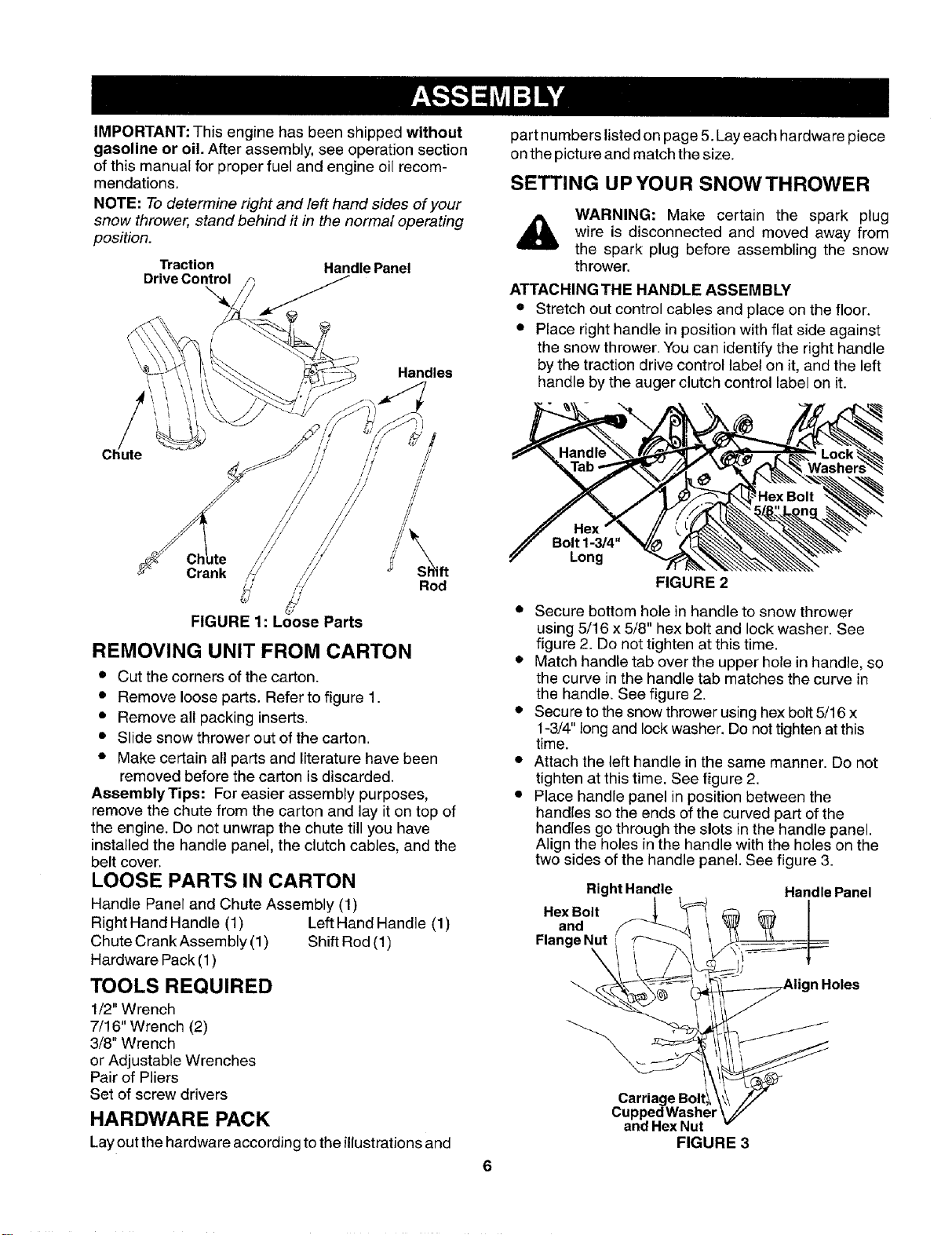
FIGURE 1: Loose Parts
REMOVING UNIT FROM CARTON
• Cut the corners of the carton.
• Remove loose parts. Refer to figure 1.
• Remove all packing inserts.
• Slide snow thrower out of the carton.
• Make certain all parts and literature have been
removed before the carton is discarded.
AssemblyTips: For easier assembly purposes,
remove the chute from the carton and lay it on top of
the engine. Do not unwrap the chute till you have
installed the handle panel, the clutch cables, and the
belt cover.
LOOSE PARTS IN CARTON
Handle Panel and Chute Assembly (1)
Right Hand Handle (1) Left Hand Handle (1)
Chute Crank Assembly (1) Shift Rod (1)
Hardware Pack (1)
TOOLS REQUIRED
1/2" Wrench
7/16" Wrench (2)
3/8" Wrench
or Adjustable Wrenches
Pair of Pliers
Set of screw drivers
HARDWARE PACK
Lay out the hardware according to the illustrationsand
part numbers listed on page 5. Lay each hardware piece
on the picture and match the size.
SETTING UPYOUR SNOWTHROWER
WARNING: Make certain the spark plug
wire is disconnected and moved away from
the spark plug before assembling the snow
thrower.
ATTACHING THE HANDLE ASSEMBLY
• Stretch out control cables and place on the floor.
• Place right handle in position with flat side against
the snow thrower. You can identify the right handle
by the traction drive control label on it, and the left
handle by the auger clutch control label on it.
Bolt 1-3/4"
Long
FIGURE 2
• Secure bottom hole in handle to snow thrower
using 5/16 x 5/8" hex bolt and lock washer. See
figure 2. Do not tighten at this time.
• Match handle tab over the upper hole in handle, so
the curve in the handle tab matches the curve in
the handle. See figure 2.
• Secure to the snow thrower using hex bolt 5/16 x
1-3/4" long and lock washer. Do not tighten atthis
time.
• Attach the left handle in the same manner. Do not
tighten at this time. See figure 2.
• Place handle panel in position between the
handles so the ends of the curved part of the
handles go through the slots inthe handle panel.
Align the holes in the handle with the holes on the
two sides of the handle panel. See figure 3.
RightHandle Handle Panel
.exOo,,on°Flange I_ .....
Carriage Boltl_
Cupped Washer
and Hex Nut
FIGURE 3
• Attach handle panel to the handle with four car-
riage bolts, cupped washers (cupped side against
the handle panel) and hex nuts as shown in figure
3. Align the contour of the carriage bolt head with
the handle.
• Attach rear of handle panel with two 1/4-20 hex
bolts and flange nuts. See figure 3. Do not tighten
at this time.
• Tighten all loose hardware on the handle assembly
in the following order -- first the hex bolts at the
bottom of the handle, then the carriage bolts, and
lastly the hex bolts on the rear of the handle panel.
ATTACHING THE CLUTCH CABLES
The Z ends of the clutch cables are h_3okedinto the
clutch grips on each handle.
• Lift the black plastic belt cover from the front of the en-
gine (shipped loose in position). Refer to figure 4.
• Remove the two self-tapping screws from the en-
gine frame that will be used to install the cover.
• Check and make sure that the cable is in the
groove of the two cable guide rollers.
Attach cables as follows.
• Thread the hex nuts all the way up the threaded
portion of the Z ends of the clutch cables.
• Place the clutch grip in the raised (up) position.
• Thread the cable onto the threaded portion of the
Z until there is no slack in the cable, but the cable
is NOT tight. Do not overtighten cable.
• Squeeze the auger control lever against the handle
and make sure that the belts are tightening
• When correct adjustment is reached, tighten the
hex nut against the bottom portion of the cable to
lock it in position. Use pliers and 3/8" wrench to
lock the hex nut.
• Tighten traction drive control cable in the same
manner.
• Place belt cover in position and secure with self-
tapping screws that you had earlier removed.
WARNING: If there is tension on the cable when the
clutch grip is released, the safety features of the snow
thrower may be overridden.
Belt
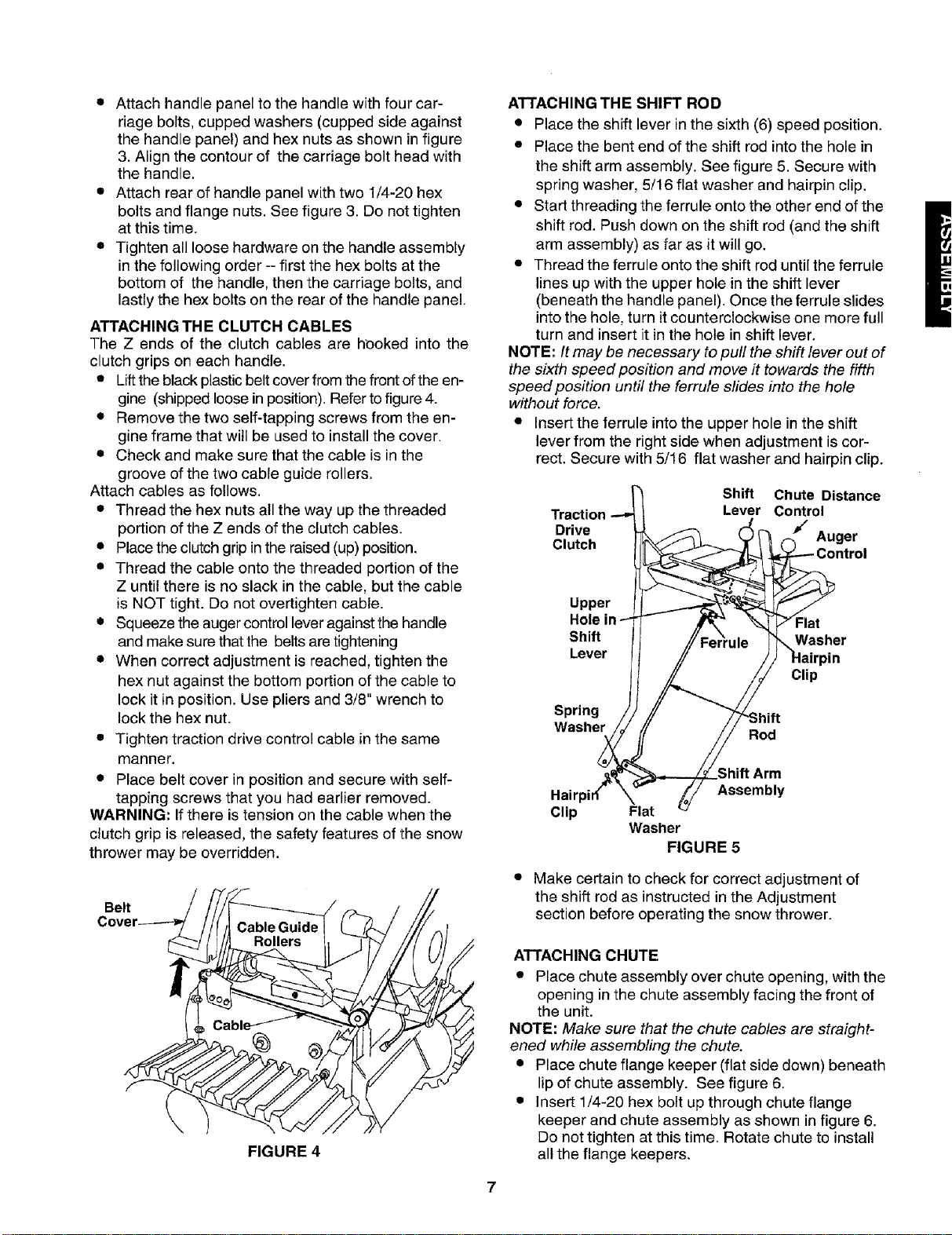
ATTACHING THE SHIFT ROD
• Place the shift lever in the sixth (6) speed position.
• Place the bent end of the shift rod into the hole in
the shift arm assembly. See figure 5. Secure with
spring washer, 5/16 flat washer and hairpin clip.
• Start threading the ferrule onto the other end of the
shift rod. Push down on the shift rod (and the shift
arm assembly) as far as it will go.
• Thread the ferrule onto the shift rod until the ferrule
lines up with the upper hole in the shift lever
(beneath the handle panel). Once the ferrule slides
into the hole, turn it counterclockwise one more full
turn and insert it in the hole in shift lever.
NOTE: It may be necessary to puff the shift lever out of
the sixth speed position and move it towards the fifth
speed position until the ferrule slides into the hole
without force.
• Insert the ferrule into the upper hole in the shift
lever from the right side when adjustment is cor-
rect. Secure with 5/16 flat washer and hairpin clip.
Shift Chute
Distance
Traction _ Contro_
Drive / Auger
Clutch
ntrol
Upper
Hole in ,,_Washer
Shift I"-'F_ /!_errule_, 7Flat
Lever H _ ///_ HairpinClip
Spring / / // --i-z....
• . /! II it-'om_
--ne j //oo0
_,_Shift Arm
Hairpir_" _" _j// Assembly
Clip Flat
Washer
FIGURE 5
• Make certain to check for correct adjustment of
the shift rod as instructed in the Adjustment
section before operating the snow thrower.
FIGURE 4
ATTACHING CHUTE
• Place chute assembly over chute opening, with the
opening in the chute assembly facing the front of
the unit.
NOTE: Make sure that the chute cables are straight-
ened while assembling the chute.
• Place chute flange keeper (flat side down) beneath
lip of chute assembly. See figure 6.
• Insert 1/4-20 hex bolt up through chute flange
keeper and chute assembly as shown in figure 6.
Do not tighten at this time. Rotate chute to install
all the flange keepers.
7
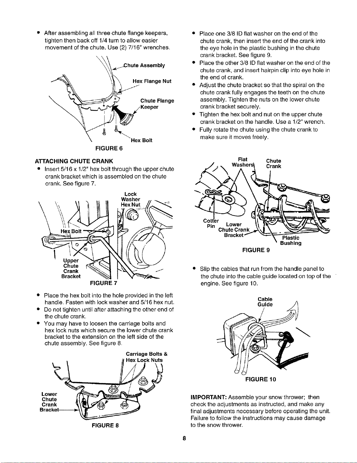
• After assembling all three chute flange keepers,
tighten then back off 1/4 turn to allow easier
movement of the chute. Use (2) 7/16" wrenches.
\ \
_Chute Assembly
Hex Flange Nut
Chute Flange
Hex Bolt
FIGURE 6
ATTACHING CHUTE CRANK
• Insert 5/16 x 1/2" hex bolt through the upper chute
crank bracket which is assembled on the chute
crank. See figure 7.
HexBolt
Lock
Washer
Hex Nut
Upper
Chute
Crank
Bracket
FIGURE 7
• Place the hex bolt into the hole provided in the left
handle. Fasten with lock washer and 5/16 hex nut.
• Do not tighten until after attaching the other end of
the chute crank,
• You may have to loosen the carriage bolts and
hex lock nuts which secure the lower chute crank
bracket to the extension on the left side of the
chute assembly. See figure 8.
Carriage Bolts &
Hex Lock Nuts
• Place one 3/8 ID flat washer on the end of the
chute crank, then insert the end of the crank into
the eye hole in the plastic bushing in the chute
crank bracket. See figure 9.
• Place the other 3/8 ID flat washer on the end of the
chute crank, and insert hairpin clip into eye hole in
the end of crank.
• Adjust the chute bracket so that the spiral on the
chute crank fully engages the teeth on the chute
assembly. Tighten the nuts on the lower chute
crank bracket securely.
• Tighten the hex bolt and nut on the upper chute
crank bracket on the handle. Use a 1/2" wrench,
• Fully rotate the chute using the chute crank to
make sure it moves freely.
Flat Chute
___t__ Washers_ Crank
Pin Lower
ChuteCra Bushing
Bracket Plastic
FIGURE 9
• Slip the cables that run from the handle panel to
the chute into the cable guide located on top of the
engine. See figure 10,
Cable
Guide
FIGURE 10
Lower
Chute
Crank
FIGURE 8
IMPORTANT: Assemble your snow thrower; then
check the adjustments as instructed, and make any
final adjustments necessary before operating the unit.
Failure to follow the instructions may cause damage
to the snow thrower.
8
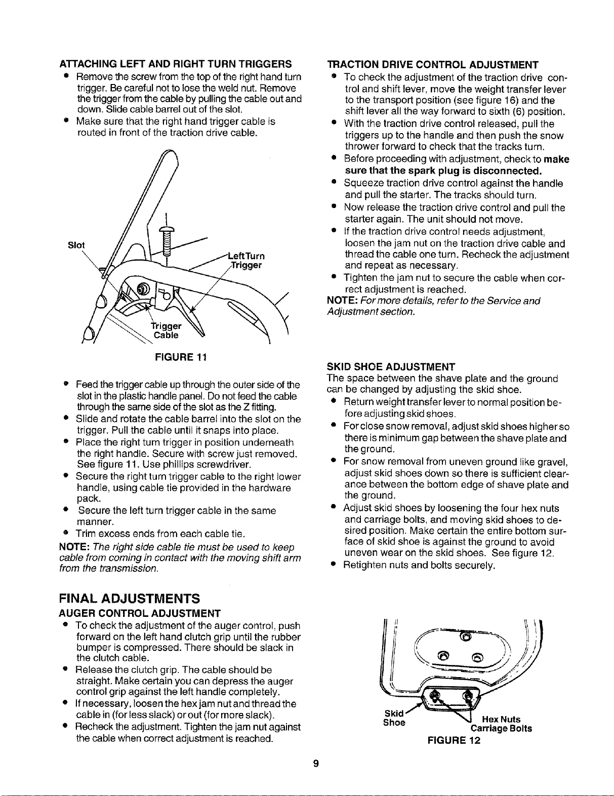
ATTACHINGLEFTANDRIGHTTURNTRIGGERS
• Remove the screw from the top of the right hand turn
trigger. Be careful not to lose the weld nut. Remove
the trigger from the cable by pulling the cable out and
down. Slide cable barrel out of the slot.
• Make sure that the right hand trigger cable is
routed in front of the traction drive cable.
I
Slot
TRACTION DRIVE CONTROL ADJUSTMENT
• To check the adjustment of the traction drive con-
trol and shift lever, move the weight transfer lever
to the transport position (see figure 16) and the
shift lever all the way forward to sixth (6) position.
• With the traction drive control released, pull the
triggers up to the handle and then push the snow
thrower forward to check that the tracks turn.
• Before proceeding with adjustment, checkto make
sure that the spark plug is disconnected.
• Squeeze traction drive control against the handle
and pull the starter. The tracks should turn.
• Now release the traction drive control and pull the
starter again. The unit should not move.
• If the traction drive control needs adjustment,
loosen the jam nut on the traction drive cable and
thread the cable one turn. Recheck the adjustment
and repeat as necessary.
• Tighten the jam nut to secure the cable when cor-
rect adjustment is reached.
NOTE: For more details, refer to the Service and
Adjustment section.
FIGURE 11
• Feed the triggercable up throughthe outer side of the
slot in the plastic handle panel. Do not feed the cable
through the same side ofthe slot as the Z fitting.
• Slide and rotate the cable barrel into the slot on the
trigger. Pull the cable until it snaps into place.
• Place the right turn trigger in position underneath
the right handle. Secure with screw just removed.
See figure 11. Use phillips screwdriver.
• Secure the right turn trigger cable to the right lower
handle, using cable tie provided in the hardware
pack.
• Secure the left turn trigger cable in the same
manner.
• Trim excess ends from each cable tie.
NOTE: The right side cable tie must be used to keep
cable from coming in contact with the moving shift arm
from the transmission.
SKID SHOE ADJUSTMENT
The space between the shave plate and the ground
can be changed by adjusting the skid shoe.
• Return weight transfer lever to normal position be-
fore adjusting skid shoes.
• For close snow removal, adjust skid shoes higher so
there is minimum gap between the shave plate and
the ground.
• For snow removal from uneven ground like gravel,
adjust skid shoes down so there is sufficient clear-
ance between the bottom edge of shave plate and
the ground.
• Adjust skid shoes by loosening the four hex nuts
and carriage bolts, and moving skid shoes to de-
sired position. Make certain the entire bottom sur-
face of skid shoe is against the ground to avoid
uneven wear on the skid shoes. See figure 12.
• Retighten nuts and bolts securely.
FINAL ADJUSTMENTS
AUGER CONTROL ADJUSTMENT
• To check the adjustment of the auger control, push
forward on the left hand clutch grip until the rubber
bumper is compressed. There should be slack in
the clutch cable.
• Release the clutch grip. The cable should be
straight. Make certain you can depress the auger
control grip against the left handle completely.
• If necessary, loosen the hex jam nut and thread the
cable in (for less slack) or out (for more slack).
• Recheck the adjustment. Tighten the jam nut against
the cable when correct adjustment is reached.
Skid
Shoe
Hex Nuts
Carriage Bolts
FIGURE 12
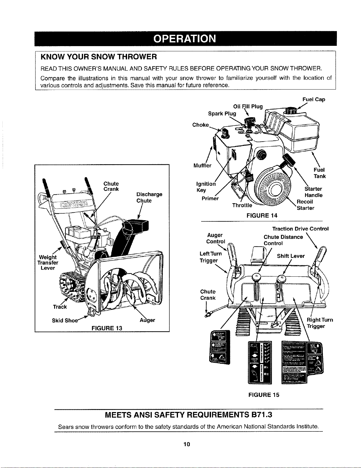
KNOW YOUR SNOW THROWER
READ THIS OWNER'S MANUAL AND SAFETY RULES BEFORE OPERATING YOUR SNOW THROWER.
Compare the illustrations in this manual with your snow thrower to familiarize yourself with the location of
various controls and adjustments. Save this manual for future reference.
Fuel Cap
Oil Fill Plug
Spark Plug
Weight
Transfer
Lever
Skid
Chute
Crank
Discharge
Chute
/
A_ger
FIGURE 13
Muffler
\
Fuel
Tank
Ig
Key Starter
Primer Handle
Recoil
Throttle
FIGURE 14
Traction Drive Control
Auger Chute Distance \
Control Control
\
LeftTurn Shift Lever
Trigger
Chute
Crank
Right Turn
Trigger
FIGURE 15
MEETS ANSI SAFETY REQUIREMENTS B71.3
Sears snow throwers conform to the safety standards of the American National Standards Institute.
10
The operation of any snow thrower can result in foreign objects being thrown into the eyes, which
can result in severe eye damage. Always wear safety glasses or eye shields while operating the
snow thrower or performing any adjustments or repairs. We recommend standard safety glasses
or wide vision safety mask for over your glasses available at SEARS retail stores.
OPERATION CONTROLS
CHUTE CRANK
The chute crank is located on left hand side of the
snow thrower. See figure 13.To change the direction in
which snow is thrown, turn chute crank as follows: turn
clockwise to discharge to the left; turn counterclock-
wise to discharge to the right.
THROTTLE CONTROL
The throttle control is located on the engine. It
regulates the speed of the engine. See figure 14.
SAFETY IGNITION SWITCH
The ignition key must be inserted into the switch for
the unit to start. Remove the ignition key when snow
thrower is not in use. See figure 14.
LEFT AND RIGHT TURN TRIGGER
The left and right turn triggers are located on the
underside of the handles and are used to assist in
steering your snow thrower. See figure 15. Squeeze
the right turn trigger when turning right, squeeze the
left turn trigger when turning left. Operate your snow
thrower in open areas until you become familiar with
these controls.
SHIFT LEVER
The shift lever is located in the center of the handle
panel. The shift lever may be moved into one of eight
positions. Use the shift lever to determine ground
speed. Forward---one of six speeds; position one (1) is
the slowest and position six (6) isthe fastest.
Reverse--two reverse (R) speeds; R2 is faster.
AUGER CONTROL
The auger control is located on the left handle. See
figure 15. Squeeze the auger control against the
handle to engage the augers; release to disengage
the augers. (Traction drive control must also be
released.)
TRACTION DRIVE CONTROL
The traction drive control is located on the right han-
dle. Squeeze the traction drive control to engage the
track drive; release to stop. See figure 15.
This same lever also locks the auger control so
you can turn the chute crank without interrupting
the snow throwing process. If the auger control is
engaged with the traction drive control engaged, you
can release the auger control (on the left handle) and
the augers will remain engaged. Release the traction
drive control to stop both the augers and wheel drive.
(Auger control must also be released).
CHUTE DISTANCE CONTROL
The distance snow is thrown can be adjusted by
adjusting the angle of the chute assembly. Move the
chute distance control forward to decrease the dis-
tance, toward the rear to increase the distance. See
figure 15.
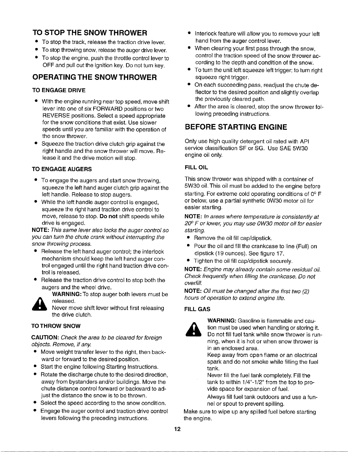
WEIGHT TRANSFER LEVER
The weight transfer lever is located on the right side of
the snow thrower and is used to select the position of
the housing and the method of track operation. Move
the lever to the right, then forward or backward to one
of the three positions. See figure 16.
Transport--Raises the front end of the snow
thrower for easy transport. Using proper caution,
this position may also be used on many gravel drive-
ways to clear snow while leaving gravel undisturbed.
Normal Snow--Allows the tracks to be suspended
independently for continuous ground contact.
Packed Snow--Locks the front end of the snow
thrower down to the ground for hard-packed or icy
snow conditions.
Position
Position
Normal
Snow
FIGURE 16
11
TO STOP THE SNOW THROWER
• To stop the track, release the traction drive lever.
• To stop throwing snow, release the auger drive lever.
• To stop the engine, push the throttle control lever to
OFF and pull out the ignition key. Do not turn key.
OPERATING THE SNOW THROWER
TO ENGAGE DRIVE
• With the engine running near top speed, move shift
lever into one of six FORWARD positions or two
REVERSE positions. Select a speed appropriate
for the snow conditions that exist. Use slower
speeds until you are familiar with the operation of
the snow thrower.
• Squeeze the traction drive clutch grip against the
right handle and the snow thrower will move. Re-
lease it and the drive motion will stop.
TO ENGAGE AUGERS
• To engage the augers and start snow throwing,
squeeze the left hand auger clutch grip against the
left handle. Release to stop augers.
• While the left handle auger control is engaged,
squeeze the right hand traction drive control to
move, release to stop. Do not shift speeds while
drive is engaged.
NOTE: This same lever also locks the auger control so
you can turn the chute crank without interrupting the
snow throwing process.
• Release the left hand auger control; the interlock
mechanism should keep the left hand auger con-
trol engaged until the right hand traction drive con-
trol is released.
• Release the traction drive control to stop both the
augers and the wheel drive.
WARNING: To stop auger both levers must be
_ released.
Never move shift lever without first releasing
the drive clutch.
TO THROW SNOW
CAUTION: Check the area to be cleared for foreign
objects. Remove, if any.
• Move weight transfer lever to the right, then back-
ward or forward to the desired position.
• Start the engine following Starting Instructions.
• Rotate the discharge chute to the desired direction,
away from bystanders and/or buildings. Move the
chute distance control forward or backward to ad-
just the distance the snow is to be thrown.
• Select the speed according to the snow condition.
• Engage the auger control and traction drive control
levers following the preceding instructions.
• Interlock feature will allow you to remove your left
hand from the auger control lever.
• When clearing your first pass through the snow,
control the traction speed of the snow thrower ac-
cording to the depth and condition of the snow.
• To turn the unit left squeeze left trigger; to turn right
squeeze right trigger.
• On each succeeding pass, readjust the chute de-
flector to the desired position and slightly overlap
the previously cleared path.
• After the area is cleared, stop the snow thrower fol-
lowing preceding instructions.
BEFORE STARTING ENGINE
Only use high quality detergent oil rated with API
service classification SF or SG. Use SAE 5W30
engine oil only.
FILL OIL
This snow thrower was shipped with a container of
5W30 oil. This oil must be added to the engine before
starting. For extreme cold operating conditions of 0° F
or below, use a partial synthetic 0W30 motor oil for
easier starting.
NOTE: In areas where temperature is consistently at
20 ° F or lower, you may use OW30 motor off for easier
starting.
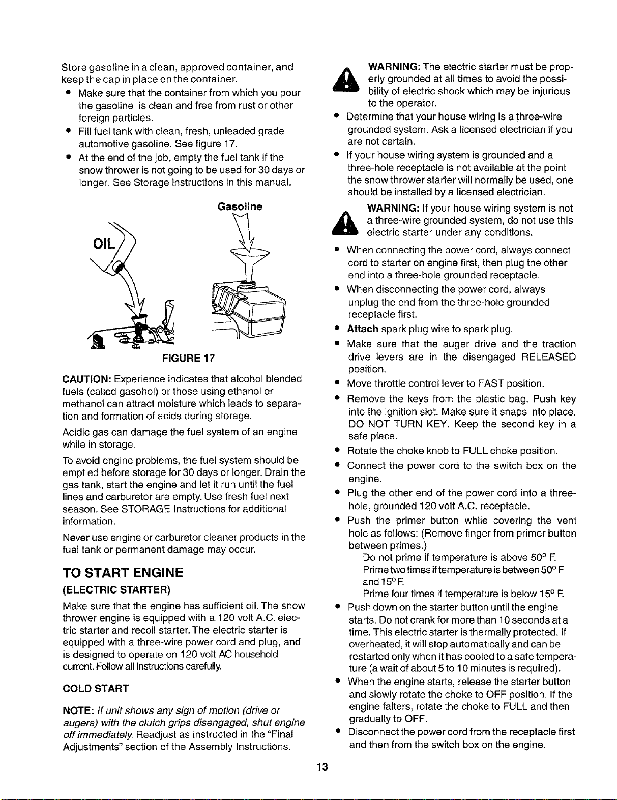
• Remove the oil fill cap/dipstick.
• Pour the oil and fill the crankcase to line (Full) on
dipstick (19 ounces). See figure 17.
• Tighten the oil fill cap/dipstick securely.
NOTE: Engine may already contain some residual oil.
Check frequently when filling the crankcase. Do not
overfill.
NOTE: Oil must be changed after the first two (2)
hours of operation to extend engine life.
FILL GAS
WARNING: Gasoline is flammable and cau-
tion must be used when handling or storing it.
Do not fill fuel tank while snow thrower is run-
ning, when it is hot or when snow thrower is
in an enclosed area.
Keep away from open flame or an electrical
spark and do not smoke while filling the fuel
tank.
Never fill the fuel tank completely. Fill the
tank to within 1/4"-1/2" from the top to pro-
vide space for expansion of fuel.
Always fill fuel tank outdoors and use a fun-
nel or spout to prevent spilling.
Make sure to wipe up any spilled fuel before starting
the engine.
12
Storegasolineinaclean,approvedcontainer,and
keepthecapinplaceonthecontainer.
• Make sure that the container from which you pour
the gasoline is clean and free from rust or other
foreign particles.
• Fill fuel tank with clean, fresh, unleaded grade
automotive gasoline. See figure 17.
• At the end of the job, empty the fuel tank if the
snow thrower is not going to be used for 30 days or
longer. See Storage instructions in this manual.
OIL
Gasoline
FIGURE 17
CAUTION: Experience indicates that alcohol blended
fuels (called gasohol) or those using ethanol or
methanol can attract moisture which leads to separa-
tion and formation of acids during storage.
Acidic gas can damage the fuel system of an engine
while in storage.
To avoid engine problems, the fuel system should be
emptied before storage for 30 days or longer. Drain the
gas tank, start the engine and let it run until the fuel
lines and carburetor are empty. Use fresh fuel next
season. See STORAGE Instructions for additional
information.
Never use engine or carburetor cleaner products in the
fuel tank or permanent damage may occur.
TO START ENGINE
(ELECTRIC STARTER)
Make sure that the engine has sufficient oil. The snow
thrower engine is equipped with a 120 volt A.C. elec-
tric starter and recoil starter. The electric starter is
equipped with a three-wire power cord and plug, and
is designed to operate on 120 volt AC household
current. Follow all instructions carefully.
COLD START
NOTE: If unit shows any sign of motion (drive or
augers) with the clutch grips disengaged, shut engine
off immediately. Readjust as instructed in the "Final
Adjustments" section of the Assembly Instructions.
13
WARNING: The electric starter must be prop-
erly grounded at all times to avoid the possi-
bility of electric shock which may be injurious
to the operator.
• Determine that your house wiring is a three-wire
grounded system. Ask a licensed electrician if you
are not certain.
• If your house wiring system is grounded and a
three-hole receptacle is not available at the point
the snow thrower starter will normally be used, one
should be installed by a licensed electrician.
WARNING: If your house wiring system is not
a three-wire grounded system, do not use this
electric starter under any conditions.
• When connecting the power cord, always connect
cord to starter on engine first, then plug the other
end into a three-hole grounded receptacle.
• When disconnecting the power cord, always
unplug the end from the three-hole grounded
receptacle first.
• Attach spark plug wire to spark plug.
• Make sure that the auger drive and the traction
drive levers are in the disengaged RELEASED
position.
• Move throttle control lever to FAST position.
• Remove the keys from the plastic bag. Push key
into the ignition slot. Make sure it snaps into place.
DO NOT TURN KEY. Keep the second key in a
safe place.
• Rotate the choke knob to FULL choke position.
• Connect the power cord to the switch box on the
engine.
• Plug the other end of the power cord into a three-
hole, grounded 120 volt A.C. receptacle.
• Push the primer button while covering the vent
hole as follows: (Remove finger from primer button
between primes.)
Do not prime if temperature is above 50o E
Prime two times iftemperature is between 50° F
and 15° E
Prime four times if temperature is below 15° E
• Push down on the starter button until the engine
starts. Do not crank for more than 10 seconds at a
time. This electric starter isthermally protected. If
overheated, it will stop automatically and can be
restarted only when it has cooled to a safe tempera-
ture (a wait of about 5 to 10 minutes is required).
• When the engine starts, release the starter button
and slowly rotate the choke to OFF position. If the
engine falters, rotate the choke to FULL and then
gradually to OFF.
• Disconnect the power cord from the receptacle first
and then from the switch box on the engine.
• Allow the engine to warm up for a few minutes be-
cause the engine will not develop full power until it
reaches operating temperature.
• Operate the engine at full throttle (FAST) when
throwing snow.
WARM START
• If restarting a warm engine after a shut down, ro-
tate choke to OFF instead of FULL and do not
push the primer button.
TO START ENGINE
(RECOIL STARTER)
Make sure that the engine has sufficient oil and the
auger drive and the traction drive levers are disen-
gaged (released).
• Move throttle control to FAST position.
• Push key into the ignition slot and make sure that it
snaps into place. Do not turn key. Remove plastic
bag and keep the second key in a safe place.
• Rotate choke control to FULL choke position.
• Push the primer button while covering the vent hole.
Remove finger from primer button between primes.
Do not prime if temperature is above 50° E
Prime two times in temperatures between 50° F
and 15° F.
Prime four times in temperatures below 15° E
• Pull the starter handle rapidly. Do not allow the
handle to snap back, but allow it to rewind slowly
while keeping a firm hold on the starter handle.
• As the engine warms up and begins to operate
evenly, rotate the choke knob slowly to OFF posi-
tion. if the engine falters, return to FULL choke,
then slowly move to OFF choke position.
• Allow the engine to warm up for a few minutes be-
cause the engine wil! not develop full power until it
reaches operating temperature.
• Operate the engine at full throttle (FAST) when
throwing snow.
WARM START
• If restarting a warm engine after a shut down, ro-
tate choke to OFF instead of FULL and do not
push the primer button.
FROZEN RECOIL STARTER
If the starter is frozen and will not turn the engine, pro-
ceed as follows:
• Pull as much rope out of the starter as possible.
• Release the starter handle and let it snap back
against the starter.
• If the engine still fails to start, repeat the first two
steps. If continued attempts do not free starter,
follow the electric starter procedures to start.
Avoid possible freezing of recoil starter and the engine
controls.
OPERATING TIPS
NOTE: Allow the engine to warm up for a few minutes
as the engine will not develop full power until it
reaches operating temperature.
Warning: Temperature of muffler and
surrounding areas may exceed 150° E Avoid
these areas.
• For most efficient snow removal, remove snow
immediately after it falls.
• Discharge snow downwind whenever possible.
Slightly overlap each previous swath.
• Set the skid shoes 1/4" below the scraper bar for
normal usage. The skid shoes may be adjusted
upward for hard-packed snow. Adjust downward
when using on gravel or crushed rock.
• Follow the precautions listed under "To Stop
Engine" and "Frozen Recoil Starter" to prevent
possible freeze-up.
• Clean the snow thrower thoroughly after each use.
14
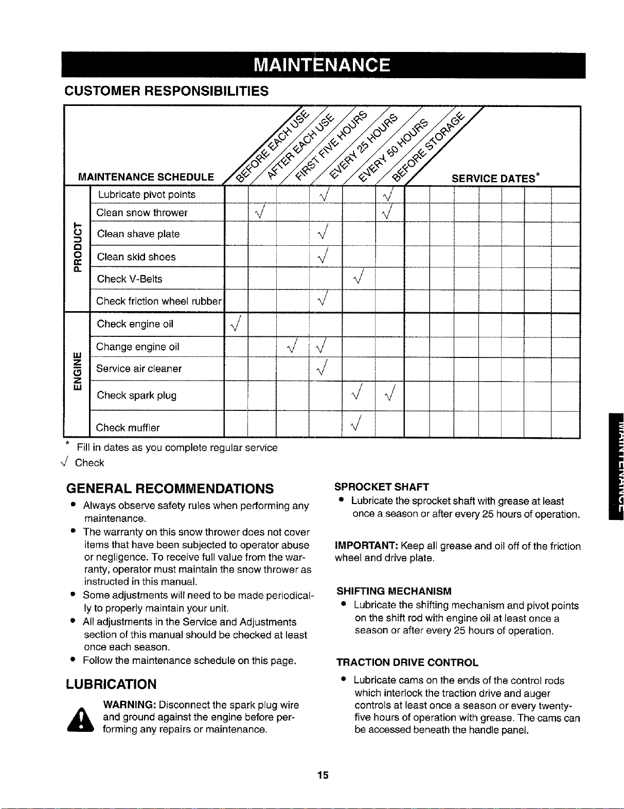
CUSTOMER RESPONSIBILITIES
MAINTENANCE SCHEDULE
Lubricate pivot points
Clean snow thrower
I,.-
O Clean shave plate
8
Clean skid shoes
n
Check V-Belts
Check friction wheel rubber
Check engine oil
Change engine oil
W
Z
Service air cleaner
I ]J J
[
,
i
J
z
= Check spark plug _/ %/
Check muffler _/
* Fill in dates as you complete regular service
_/ Check
DATES*
GENERAL RECOMMENDATIONS
• Always observe safety rules when performing any
maintenance.
• The warranty on this snow thrower does not cover
items that have been subjected to operator abuse
or negligence. To receive full value from the war-
ranty, operator must maintain the snow thrower as
instructed inthis manual.
• Some adjustments will need to be made periodical-
ly to properly maintain your unit.
• All adjustments in the Service and Adjustments
section of this manual should be checked at least
once each season.
• Follow the maintenance schedule on this page.
LUBRICATION
WARNING: Disconnect the spark plug wire
and ground against the engine before per-
forming any repairs or maintenance.
SPROCKET SHAFT
• Lubricate the sprocket shaft with grease at least
once a season or after every 25 hours of operation.
IMPORTANT: Keep all grease and oil off of the friction
wheel and drive plate.
SHIFTING MECHANISM
• Lubricate the shifting mechanism and pivot points
on the shift rod with engine oil at least once a
season or after every 25 hours of operation.
TRACTION DRIVE CONTROL
Lubricate cams on the ends of the control rods
which interlock the traction drive and auger
controls at least once a season or every twenty-
five hours of operation with grease. The cams can
be accessed beneath the handle panel.
15
GEAR CASE
• The gear case is lubricated with grease at the
factory and does not require checking. If
disassembled for any reason, lubricate with 2
ounces of Shell Alvania grease.
BEARINGS
• Lubricate the auger bearings, wheel bearings and
the bearings on the side of the frame once a
season with light oil.
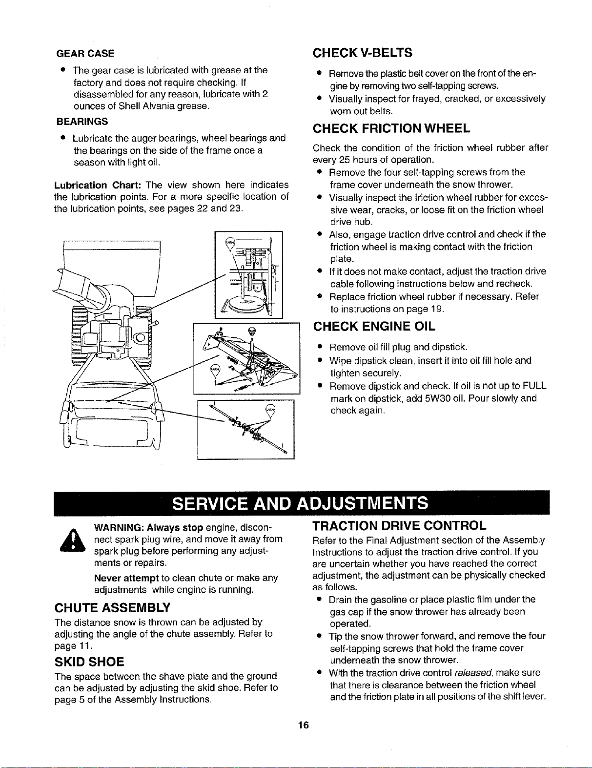
Lubrication Chart: The view shown here indicates
the lubrication points. For a more specific location of
the lubrication points, see pages 22 and 23.
CHECK V-BELTS
• Remove the plastic belt cover on the front of the en-
gine by removing two self-tapping screws.
• Visually inspect for frayed, cracked, or excessively
worn out belts.
CHECK FRICTION WHEEL
Check the condition of the friction wheel rubber after
every 25 hours of operation.
• Remove the four self-tapping screws from the
frame cover underneath the snow thrower.
• Visually inspect the friction wheel rubber for exces-
sive wear, cracks, or loose fit on the friction wheel
drive hub.
• Also, engage traction drive control and check if the
friction wheel is making contact with the friction
plate.
• If it does not make contact, adjust the traction drive
cable following instructions below and recheck.
• Replace friction wheel rubber if necessary. Refer
to instructions on page 19.
CHECK ENGINE OIL
• Remove oil fill plug and dipstick.
• Wipe dipstick clean, insert it into oil fill hole and
tighten securely.
• Remove dipstick and check. Ifoil is not up to FULL
mark on dipstick, add 5W30 oil. Pour slowly and
check again.
WARNING: Always stop engine, discon-
nect wire, and move it from
spark plug away
spark plug before performing any adjust-
ments or repairs.
Never attempt to clean chute or make any
adjustments while engine is running.
CHUTE ASSEMBLY
The distance snow is thrown can be adjusted by
adjusting the angle of the chute assembly. Refer to
page 11.
SKID SHOE
The space between the shave plate and the ground
can be adjusted by adjusting the skid shoe. Refer to
page 5 of the Assembly Instructions.
TRACTION DRIVE CONTROL
Refer to the Final Adjustment section of the Assembly
Instructions to adjust the traction drive control. If you
are uncertain whether you have reached the correct
adjustment, the adjustment can be physically checked
as follows.
• Drain the gasoline or place plastic film under the
gas cap if the snow thrower has already been
operated.
• Tip the snow thrower forward, and remove the four
self-tapping screws that hold the frame cover
underneath the snow thrower.
• With the traction drive control released, make sure
that there is clearance between the friction wheel
and the friction plate in all positions of the shift lever.
16
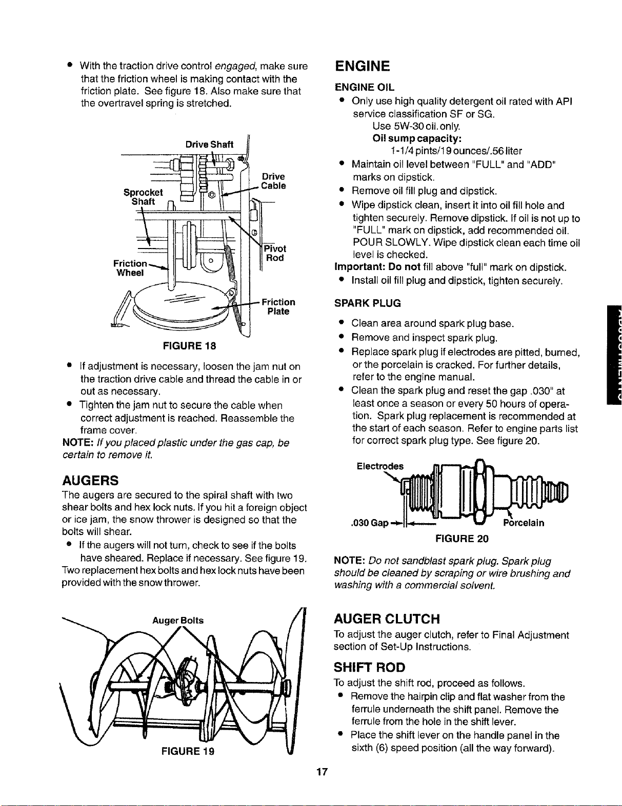
• With the traction drive control engaged, make sure
that the friction wheel is making contact with the
friction plate. See figure 18. Also make sure that
the overtravel spring is stretched.
Drive Shaft
Sprocket
Shaft
Drive
Wheel
Pivot
Rod
Friction
Plate
FIGURE 18
• if adjustment is necessary, loosen the jam nut on
the traction drive cable and thread the cable in or
out as necessary.
• Tighten the jam nut to secure the cable when
correct adjustment is reached. Reassemble the
frame cover.
NOTE: If you placed plastic under the gas cap, be
certain to remove it.
AUGERS
The augers are secured to the spiral shaft with two
shear bolts and hex lock nuts. If you hit a foreign object
or ice jam, the snow thrower is designed so that the
bolts will shear.
• If the augers will not turn, check to see ifthe bolts
have sheared. Replace if necessary. See figure 19.
Two replacement hex bolts and hex lock nuts have been
provided with the snow thrower.
ENGINE
ENGINE OIL
• Only use high quality detergent oil rated with API
service classification SF or SG.
Use 5W-30 oil.only.
Oil sump capacity:
1-1/4 pints/19 ounces/.56 liter
• Maintain oil level between "FULL" and "ADD"
marks on dipstick.
• Remove oil fill plug and dipstick.
• Wipe dipstick clean, insert it into oil fill hole and
tighten securely. Remove dipstick. If oil is not up to
"FULL" mark on dipstick, add recommended oil.
POUR SLOWLY. Wipe dipstick clean each time oil
level is checked,
Important: Do not fill above "full" mark on dipstick.
• Install oil fill plug and dipstick, tighten securely.
SPARK PLUG
• Clean area around spark plug base.
• Remove and inspect spark plug.
• Replace spark plug if electrodes are pitted, burned,
or the porcelain is cracked. For further details,
refer to the engine manual.
• Clean the spark plug and reset the gap .030" at
least once a season or every 50 hours of opera-
tion. Spark plug replacement is recommended at
the start of each season. Refer to engine parts list
for correct spark plug type. See figure 20.
Electrodes
.030 Gal
FIGURE 20
NOTE: Do not sandblast spark plug. Spark ptug
should be cleaned by scraping or wire brushing and
washing with a commercial solvent.
Auger Bolts
FIGURE 19
AUGER CLUTCH
To adjust the auger clutch, refer to Final Adjustment
section of Set-Up Instructions.
SHIFT ROD
To adjust the shift rod, proceed as follows.
• Remove the hairpin clip and flat washer from the
ferrule underneath the shift panel. Remove the
ferrule from the hole inthe shift lever.
• Place the shift lever on the handle panel in the
sixth (6) speed position (all the way forward).
17
• Push down on the shift rod (and shift arm assem-
bly) as far as it will go. Hold it in this position.
• Thread the ferrule up or down the shift rod as
necessary until the ferrule lines up with the upper
hole in the shift lever. Refer to figure 9.
• Insert ferrule into the upper hole in the shift lever
from the right side when adjustment is correct.
Secure with flat washer and hairpin clip.
• Before operating the snow thrower, check for cor-
rect adjustment of the traction drive control as in-
structed inthe Final Adjustment section.
CARBURETOR
WARNING: If any adjustments are made to
the engine while the engine is running (e.g.
carburetor), keep clear of all moving parts.
Be careful of heated surfaces and muffler.
If you think your carburetor needs adjusting,
see your nearest authorized Tecumseh
Service Outlet.
SHAVE PLATE AND SKID SHOES
The shave plate and skid shoes on the bottom of the
snow thrower are subject to wear. They should be
checked periodically and replaced when necessary.
• To remove skid shoes, remove the four carriage
bolts, belleville washers and hex nuts which attach
them to the snow thrower.
• Reassemble new skid shoes with the four carriage
bolts, belleville washers (cupped side goes against
skid shoes) and hex nuts. Make certain the skid
shoes are adjusted to be level.
• To remove shave plate, remove the carriage bolts,
belleville washers and hex nuts which attach it to
the snow thrower housing. Reassemble new
shave plate, making sure heads of the carriage
bolts are to the inside of the housing. Tighten
securely.
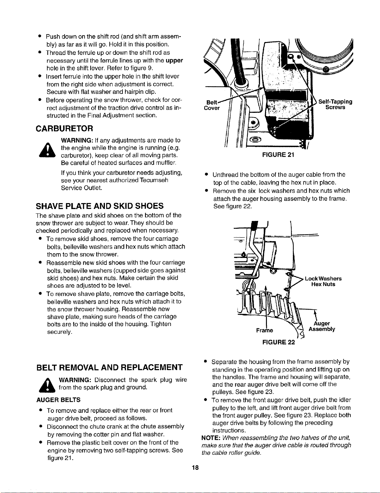
Self-Tapping
Cover Screws
/
FIGURE 21
• Unthread the bottom of the auger cable from the
top of the cable, leaving the hex nut in place.
• Remove the six lock washers and hex nuts which
attach the auger housing assembly to the frame.
See figure 22.
pLockWashers
Hex Nuts
Frame
FIGURE 22
Auger
Assembly
BELT REMOVAL AND REPLACEMENT
,_ WARNING: Disconnect the spark plug wire
from the spark plug and ground.
AUGER BELTS
• To remove and replace either the rear or front
auger drive belt, proceed as follows.
• Disconnect the chute crank at the chute assembly
by removing the cotter pin and flat washer.
• Remove the plastic belt cover on the front of the
engine by removing two self-tapping screws. See
figure 21.
• Separate the housing from the frame assembly by
standing in the operating position and lifting up on
the handles. The frame and housing will separate,
and the rear auger drive belt will come off the
pulleys. See figure 23.
• To remove the front auger drive belt, push the idler
pulley to the left, and lift front auger drive belt from
the front auger pulley. See figure 23. Replace both
auger drive belts by following the preceding
instructions.
NOTE: When reassembling the two halves of the unit,
make sure that the auger drive cable is routed through
the cable roller guide.
18
Drive Belt
AUger
Iley
FIGURE 23
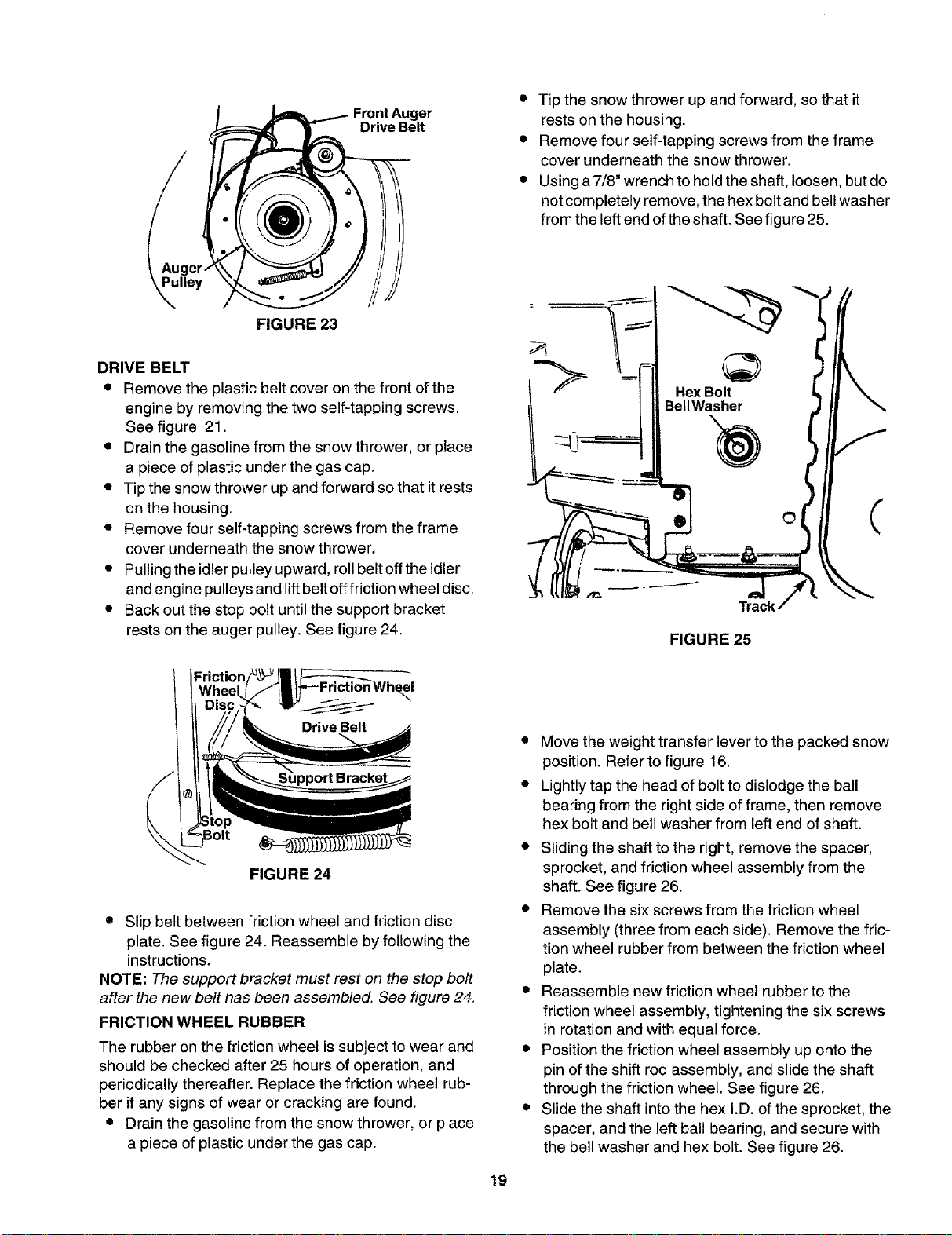
DRIVE BELT
• Remove the plastic belt cover on the front of the
engine by removing the two self-tapping screws.
See figure 21.
• Drain the gasoline from the snow thrower, or place
a piece of plastic under the gas cap.
• Tip the snow thrower up and forward so that it rests
on the housing.
• Remove four self-tapping screws from the frame
cover underneath the snow thrower.
• Pulling the idler pulley upward, roll belt off the idler
and engine pulleys and lift belt off friction wheel disc.
• Back out the stop bolt until the support bracket
rests on the auger pulley. See figure 24.
• Tip the snow thrower up and forward, so that it
rests on the housing.
• Remove four self-tapping screws from the frame
cover underneath the snow thrower.
• Using a 7/8" wrench to hold the shaft, loosen, but do
not completely remove, the hex bolt and bell washer
from the left end of the shaft. See figure 25.
HexBolt
BellWasher
FIGURE 25
FIGURE 24
\
• Slip belt between friction wheel and friction disc
plate. See figure 24. Reassemble by following the
instructions.
NOTE: The support bracket must rest on the stop bolt
after the new belt has been assembled. See figure 24.
FRICTION WHEEL RUBBER
The rubber on the friction wheel is subject to wear and
should be checked after 25 hours of operation, and
periodically thereafter. Replace the friction wheel rub-
ber if any signs of wear or cracking are found.
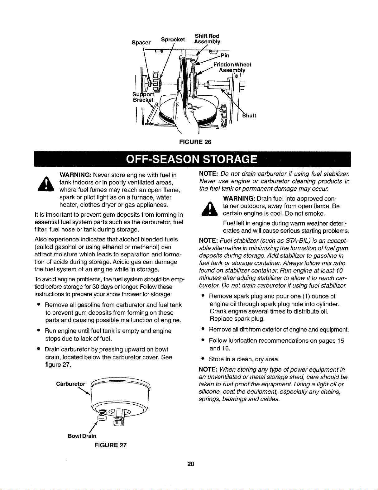
• Drain the gasoline from the snow thrower, or place
a piece of plastic under the gas cap.
• Move the weight transfer lever to the packed snow
position. Refer to figure 16.
• Lightly tap the head of bolt to dislodge the ball
bearing from the right side of frame, then remove
hex bolt and bell washer from left end of shaft.
• Sliding the shaft to the right, remove the spacer,
sprocket, and friction wheel assembly from the
shaft. See figure 26.
• Remove the six screws from the friction wheel
assembly (three from each side). Remove the fric-
tion wheel rubber from between the friction wheel
plate.
• Reassemble new friction wheel rubber to the
friction wheel assembly, tightening the six screws
in rotation and with equal force.
• Position the friction wheel assembly up onto the
pin of the shift rod assembly, and slide the shaft
through the friction wheel. See figure 26.
• Slide the shaft into the hex I.D. of the sprocket, the
spacer, and the left ball bearing, and secure with
the bell washer and hex bolt. See figure 26.
19
Shift Rod
Spacer Sprocket Assembly
JU
Bracl
FrictionWheel
Assembly
;haft
FIGURE 26
WARNING: Never store engine with fuel in
tank indoors or in poorly ventilated areas,
where fuel fumes may reach an open flame
spark or pilot light as on a furnace, water
heater, clothes dryer or gas appliances.
It is important to prevent gum deposits from forming _n
essential fuel system parts such as the carburetor, fuel
filter, fuel hose or tank during storage.
Also experience indicates that alcohol blended fuels
(called gasohol or using ethanol or methanol) can
attract moisture which leads to separation and forma-
tion of acids during storage. Acidic gas can damage
the fuel system of an engine while in storage.
Toavoid engine problems, the fuel system should be emp-
tied before storage for 30 days or longer. Follow these
instructions to prepare your snow thrower for storage:
• Remove all gasoline from carburetor and fuel tank
to prevent gum deposits from forming on these
parts and causing possible malfunction of engine.
= Run engine until fuel tank is empty and engine
stops due to lack of fuel.
• Drain carburetor by pressing upward on bowl
drain, located below the carburetor cover. See
figure 27.
C°r0uret /
BowlDrain
FIGURE 27
NOTE: Do not drain carburetor if using fuel stabilizer,
Never use engine or carburetor cleaning products in
the fuel tank or permanent damage may occur.
WARNING: Drain fuel into approved con-
tainer outdoors, away from open flame. Be
certain engine is cool. Do not smoke.
Fuel left in engine during warm weather deteri-
orates and will cause serious starting problems.
NOTE: Fuel stabilizer (such as STA-BtL) is an accept-
able alternative in minimizing the formation of fuel gum
deposits during storage. Add stabilizer to gasoline in
fuel tank or storage container. Always follow mix ratio
found on stabilizer container. Run engine at least 10
minutes after adding stabilizer to allow it to reach car-
buretor. Do not drain carburetor if using fuel stabilizer.
• Remove spark plug and pour one (1) ounce of
engine oil through spark plug hole into cylinder.
Crank engine several times to distribute oil.
Replace spark plug.
• Remove all dirtfrom exterior of engine and equipment.
• Follow lubrication recommendations on pages 15
and 16.
• Store in a clean, dry area.
NOTE: When storing any type of power equipment in
an unventilated or metal storage shed, care should be
taken to rustproof the equipment. Using a light off or
silicone, coat the equipment, especially any chains,
springs, bearings and cables.
20
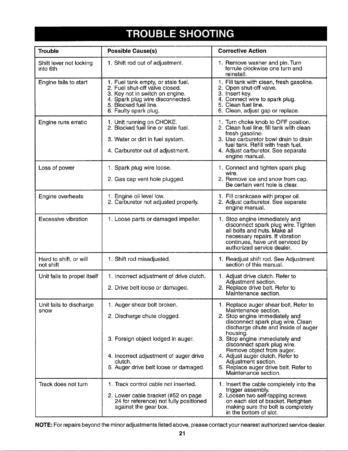
Trouble PossibleCause(s) CorrectiveAction
Shift lever not locking 1. Shift rod out of adjustment. 1. Remove washer and pin. Turn
into 6th ferrule clockwise one turn and
reinstall.
Engine fails to start
Engine runs erratic
Loss of power
1. Fuel tank empty, or stale fuel.
2. Fuel shut-off valve closed.
3. Key not in switch on engine.
4. Spark plug wire disconnected.
5. Blocked fuel line.
6. Faulty spark plug.
1. Unit running on CHOKE.
2. Blocked fuel line or stale fuel.
3. Water or dirt in fuel system.
4. Carburetor out of adjustment.
1. Spark plug wire loose.
2. Gas cap vent hole plugged.
1. Fill tank with clean, fresh gasoline.
2. Open shut-off valve.
3. Insert key.
4. Connect wire to spark plug.
5. Clean fuel line.
6, Clean, adjust gap or replace.
1• Turn choke knob to OFF position.
2. Clean fuel line; fill tank with clean
fresh gasoline.
3. Use carburetor bowl drain to drain
fuel tank. Refill with fresh fuel.
4. Adjust carburetor. See separate
engine manual.
1. Connect and tighten spark plug
wire.
2. Remove ice and snow from cap.
Be certain vent hole is clear.
Engine overheats 1. Engine oil level tow. 1. Fill crankcase with proper oil.
2
• Carburetor not adjusted properly. 2. Adjust carburetor. See separate
engine manual•
Excessive vibration 1. Loose parts or damaged impeller. 1.
1. Auger shear bolt broken.
2. Discharge chute clogged.
Stop engine immediately and
disconnect spark plug wire, Tighten
all bolts and nuts. Make all
necessary repairs. If vibration
continues, have unit serviced by
authorized service dealer.
Hard to shift, or will 1. Shift rod misadjusted. 1. Readjust shift rod. See Adjustment
not shift section of this manual.
Unit fails to propel itself 1. Incorrect adjustment of drive clutch. 1, Adjust drive clutch. Refer to
Adjustment section.
2. Drive belt loose or damaged. 2. Replace drive belt, Refer to
Maintenance section.
Unit fails to discharge
snow
Track does not turn
3. Foreign object lodged in auger.
4. Incorrect adjustment of auger drive
clutch.
5. Auger drive belt loose or damaged.
1,
2.
1, Replace auger shear bolt, Refer to
Maintenance section.
2. Stop engine immediately and
disconnect spark plug wire, Clean
discharge chute and inside of auger
housing.
3. Stop engine immediately and
disconnect spark plug wire.
Remove object from auger.
4. Adjust auger clutch. Refer to
Adjustment section.
5. Replace auger drive belt. Refer to
Maintenance section.
Track control cable not inserted. 1.
Lower cable bracket (#52 on page 2.
24 for reference) not fully positioned
against the gear box.
Insert the cable completely into the
trigger assembly.
Loosen two self-tapping screws
on each slot of bracket. Retighten
making sure the bolt is completely
in the bottom of slot.
NOTE: For repairs beyond the minor adjustments listed above, please contact your nearest authorized service dealer.
21
!
!
//
/
\
\
\
22
KEY
NO.
1
2
3
4
5
6
7
8
9
10
11
12
13
14
15
16
17
18
19
20
21
22
23
24
25
26
27
28
29
30
31
32
33
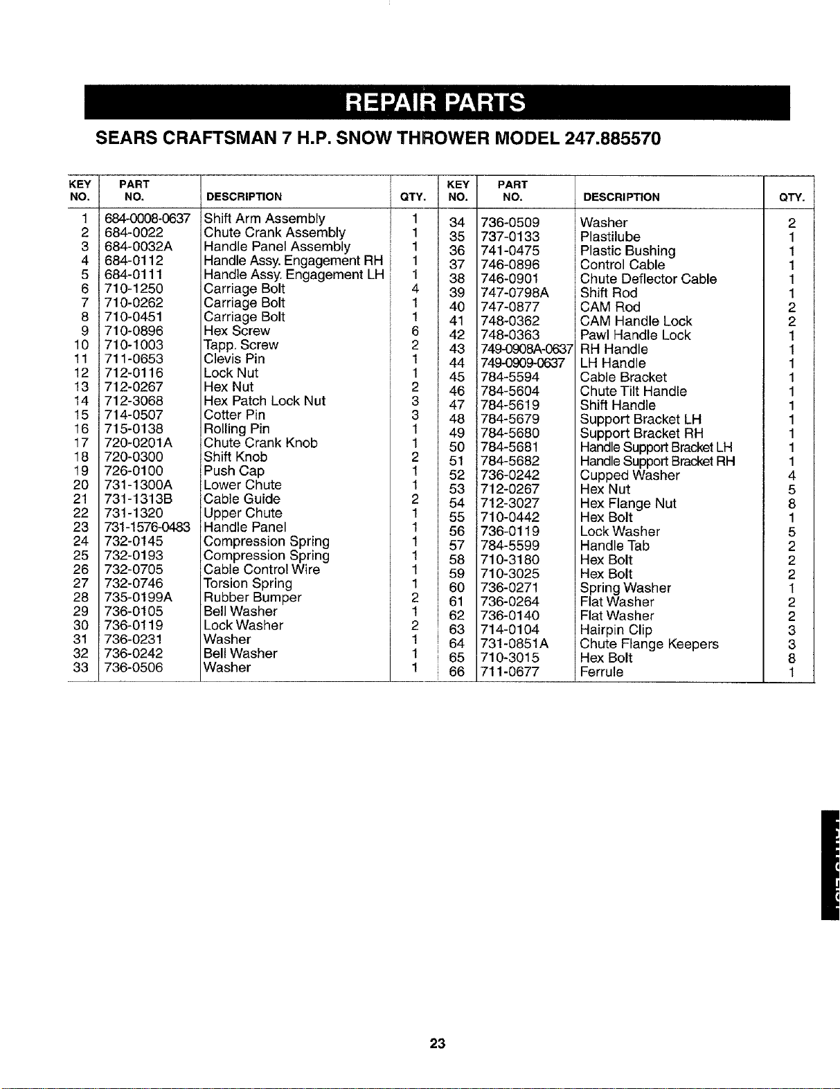
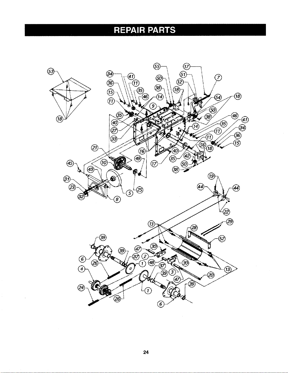
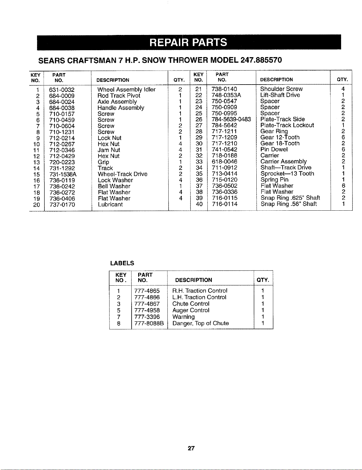
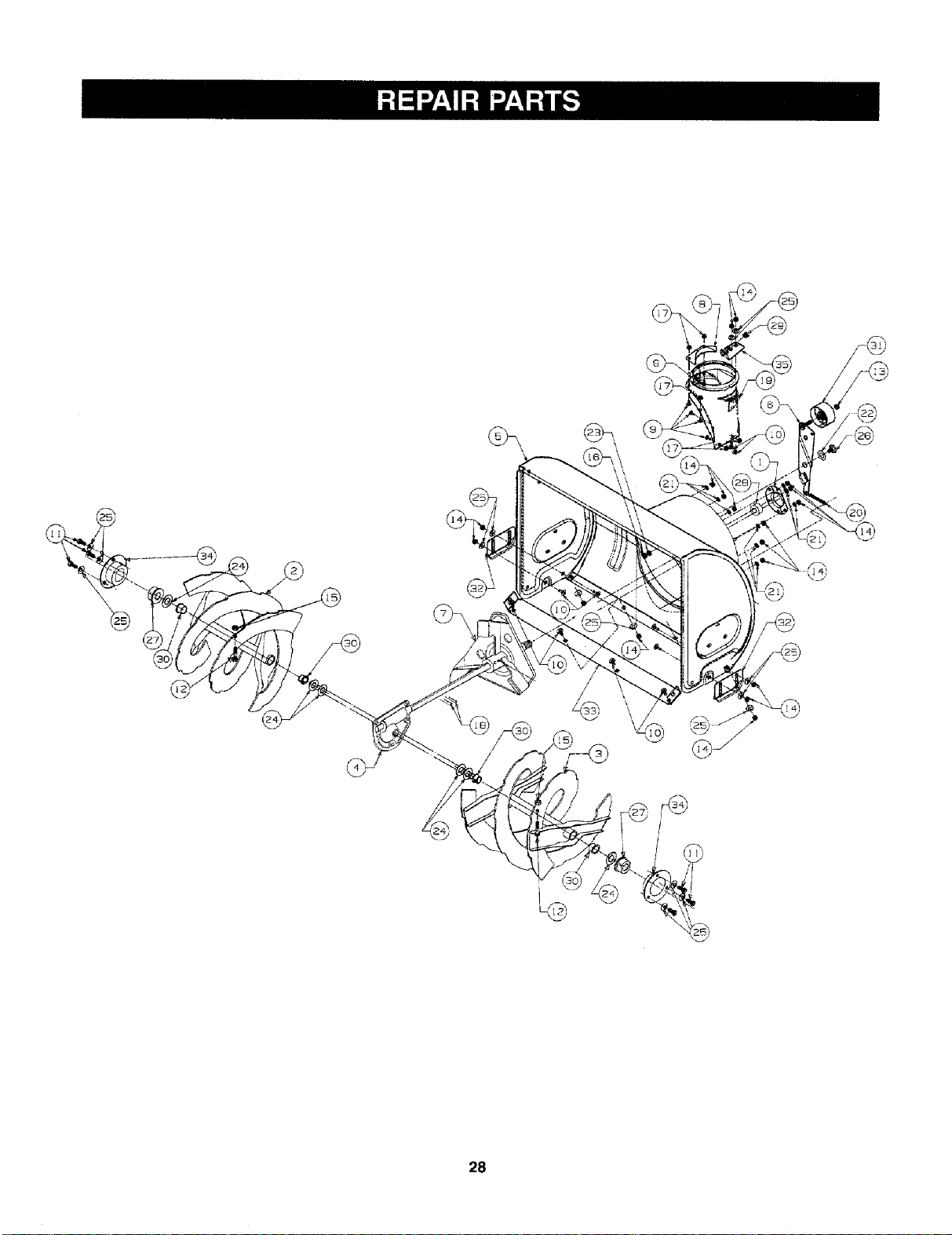
SEARS CRAFTSMAN 7 H.P. SNOW THROWER MODEL 247.885570
PART
NO.
684-0008-0637
684-0022
684-0032A
684-0112
684-0111
710-1250
710-0262
710-0451
710-0896
710-1003
711-0653
712-0116
712-0267
712-3068
714-0507
715-0138
720-0201A
720-0300
726-0100
731-1300A
731-1313B
731-1320
731-1576-0483
732-0145
732-0193
732-0705
732-0746
735-0199A
736-0105
736-0119
736-0231
736-0242
736-0506
!
DESCRIPTION QTY.
Shift Arm Assembly 1
Chute Crank Assembly i
1
Handle Panel Assembly 1
Handle Assy. Engagement RH i 11
Handle Assy. Engagement LH i
Carriage Bolt i 4
Carriage Bolt 1
Carriage Bolt i 1
KEY
NO.
34
35
36
37
38
39
40
41
PART
NO.
736-0509
737-0133
741-0475
746-0896
746-0901
747-0798A
747-0877
748-0362
DESCRI PTION
Washer
Plastilube
Plastic Bushing
Control Cable
Chute Deflector Cable
Shift Rod
CAM Rod
CAM Handle Lock
Hex Screw
"lapp. Screw
Clevis Pin
Lock Nut
Hex Nut
Hex Patch Lock Nut
Cotter Pin
Rolling Pin
Chute Crank Knob
Shift Knob
Push Cap
Lower Chute
Cable Guide
Upper Chute
Handle Panel
Compression Spring
Compression Spring
Cable Control Wire
Torsion Spring
Rubber Bumper
Bell Washer
Lock Washer
Washer
Bell Washer
Washer
6 42
12 43
44
1 45
2 46
3 47
3 48
1 49
1 50
2 51
! 52
1 53
2 54
1 65
1 56
1 57
1 58
1 59
1 60
2 I 61
1 J 62
2 163
1 I 64
1 65
1 66
748-0363
749_908A-0637
749_909-0637
784-5594
784-5604
784-5619
784-5679
784-5680
784-5681
784-5682
736-0242
712-0267
712-3027
710-0442
736-0119
784-5599
710-3180
710-3025
736-0271
736-0264
736-0140
714-0104
731-0851A
710-3015
711-0677
Pawl Handle Lock
RH Handle
LH Handle
Cable Bracket
Chute Tilt Handle
Shift Handle
Support Bracket LH
Support Bracket RH
Handle Support BracketLH
Handle Support BracketRH
Cupped Washer
Hex Nut
Hex Flange Nut
Hex Bolt
Lock Washer
Handle Tab
Hex Bolt
Hex Bolt
Spring Washer
Flat Washer
Flat Washer
Hairpin Clip
Chute Flange Keepers
Hex Bolt
Ferrule
QTY.
2
1
1
1
1
1
2
2
1
1
1
1
1
1
1
1
1
1
4
5
8
1
5
2
2
2
1
2
2
3
3
8
1
23
®\
@.
24
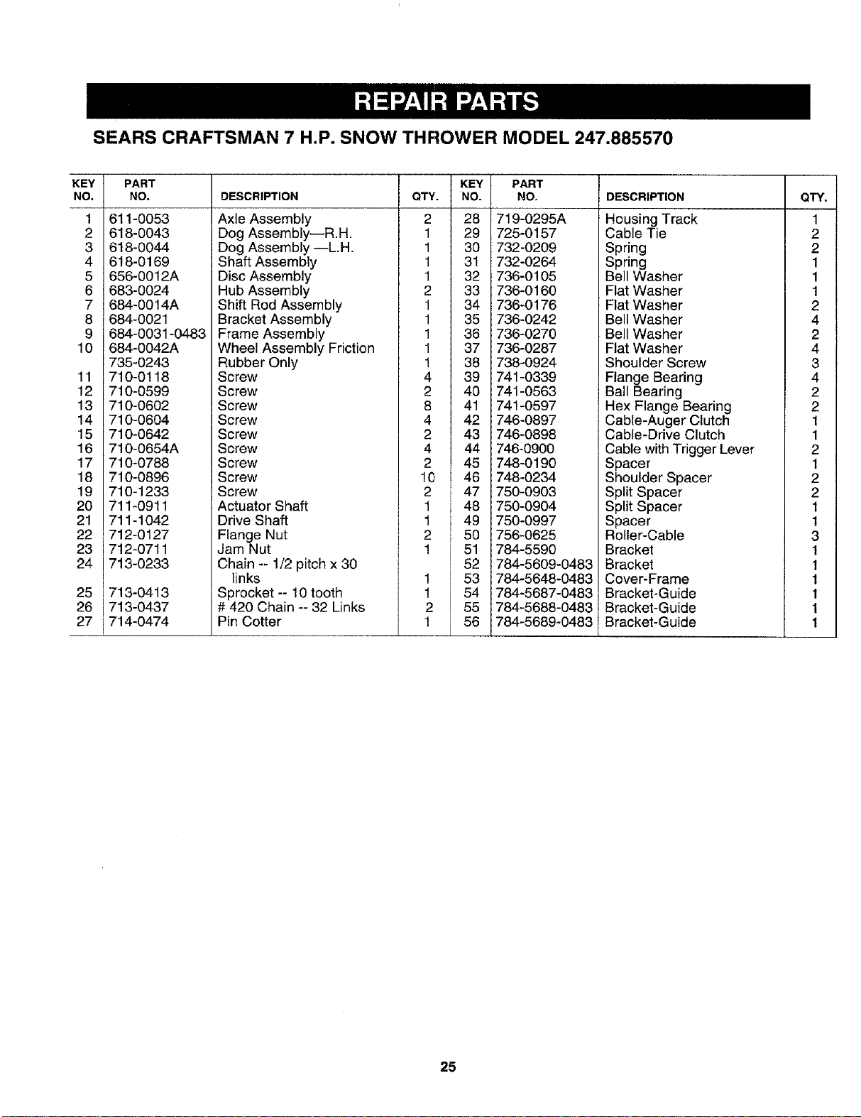
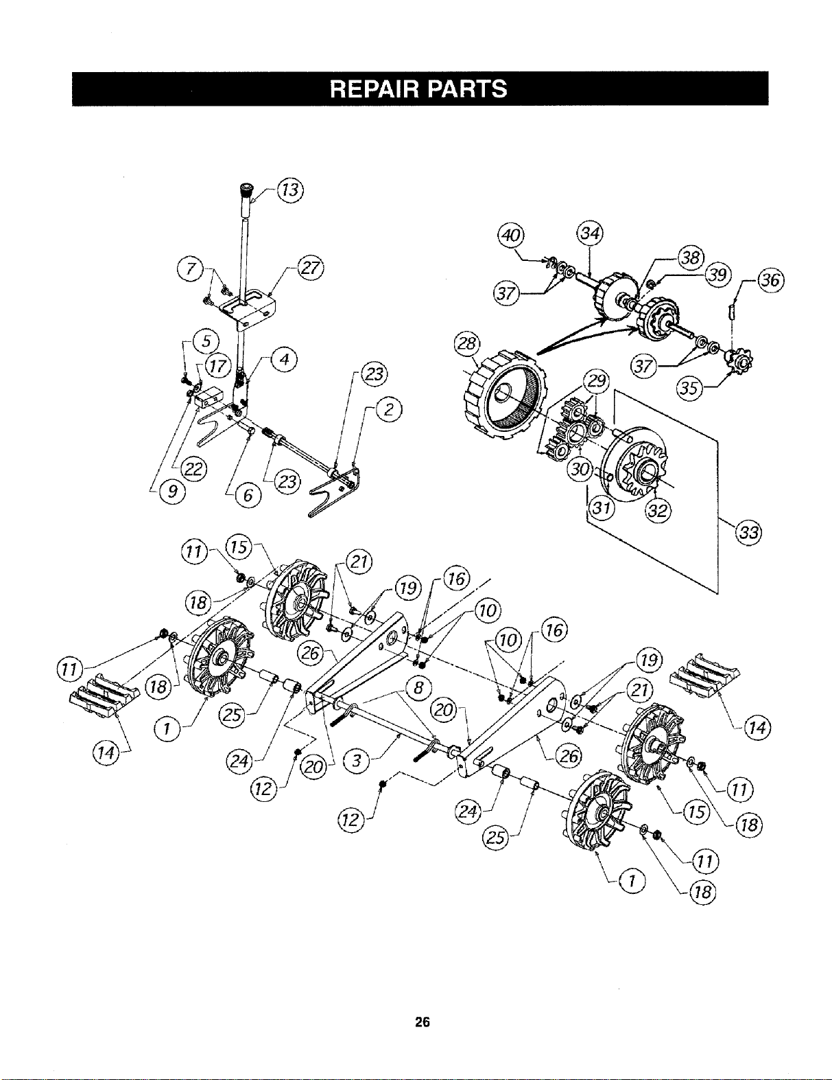
SEARS CRAFTSMAN 7 H.P. SNOW THROWER MODEL 247.885570
KEY
NO.
1
2
3
4
5
6
7
8
9
10
11
12
13
14
15
16
17
18
19
20
21
22
23
24
25
26
27
PART
NO.
611-0053
618-0043
618-0044
618-0169
656-0012A
683-0024
684-0014A
684-0021
684-0031-0483
684-0042A
735-0243
710-0118
710-0599
710-0602
710-0604
710-0642
710-0654A
710-0788
710-0896
710-1233
711-0911
711-1042
712-0127
712-0711
713-O233
713-0413
713-0437
714-0474
DESCRIPTION
Axle Assembly
Dog Assembly--R.H.
Dog Assembly --L.H.
Shaft Assembly
Disc Assembly
Hub Assembly
Shift Rod Assembly
Bracket Assembly
Frame Assembly
Wheel Assembly Friction
QTY.
2
1
1
1
1
2
1
1
1
1
KEY
NO.
28
29
30
31
32
33
34
35
36
37
PART
NO.
719-0295A
725-0157
732-0209
732-0264
736-0105
736-0160
736-0176
736-0242
736-0270
736-0287
DESCRIPTION
Housing Track
Cable Tie
Spring
Spring
Bell Washer
Flat Washer
Flat Washer
Bell Washer
Bell Washer
Flat Washer
Shoulder Screw
Flange Bearing
Ball Bearing
Hex Flange Bearing
Cable-Auger Clutch
Cable-Drive Clutch
Cable with Trigger Lever
Spacer
Shoulder Spacer
Split Spacer
Split Spacer
Spacer
Roller-Cable
Bracket
Bracket
Cover-Frame
Bracket-Guide
Bracket-Guide
Bracket-Guide
Rubber Only
Screw
Screw
Screw
Screw
Screw
Screw
Screw
Screw
Screw
Actuator Shaft
Drive Shaft
Flange Nut
Jam Nut
Chain -- 1/2 pitch x 30
links
Sprocket -- 10 tooth
# 420 Chain -- 32 Links
Pin Cotter
1
4
2
8
4
2
4
2
10
2
1
1
2
1
1
!
2
1
L
I
38 738-0924
39 741-0339
40 741-0563
41 741-0597
42 746-0897
43 746-0898
44 746-0900
45 748-0190
46 748-0234
47 750-0903
48 750-0904
49 750-0997
50 756-0625
51 784-5590
52 784-5609-0483
53 784-5648-0483
54 784-5687-0483
55 784-5688-0483
56 784-5689-0483
QTY.
1
2
2
1
1
1
2
4
2
4
3
4
2
2
1
1
2
1
2
2
1
1
3
1
1
1
1
1
1
25
@
®
®
26
SEARS CRAFTSMAN 7 H.P. SNOW THROWER MODEL 247.885570
KEY i
NO,
11
12
13
14
15
16
17
18
19
20
PART
NO. DESCRIPTION
631-0032
684-0009
684-0024
684-0038
710-0157
710-0459
710-0604
710-1231
712-0214
712-0267
712-0346
712-0429
720-0223
731-1292
731-1538A
736-0119
736-0242
736-0272
736-0406
737-0170
Wheel Assembly Idler
Rod Track Pivot
Axle Assembly
Handle Assembly
Screw
Screw
Screw
Screw
Lock Nut
Hex Nut
Jam Nut
Hex Nut
Grip
Track
Wheel-Track Drive
Lock Washer
Bell Washer
Flat Washer
Flat Washer
Lubricant
QTY.
2
1
1
1
1
1
2
2
1
4
4
2
1
2
2
4
1
4
4
KEY i
NO,
21
22
23
24
25
26
27
28
29
3O
31
32
33
34
35
36
37
38
39 i
40 i
I
PART
NO.
738-0140
748-0353A
750-0547
750-0909
750-0995
784-5639-0483
784-5642
717-1211
717-1209
717-1210
741-0542
718-0188
618-0046
711-0912
713-0414
715-0120
736-0502
736-0336
716-0115
716-0114
DESCRIPTION
Shoulder Screw
Lift-Shaft Drive
Spacer
Spacer
Spacer
Plate-Track Side
Plate-Track Lockout
Gear Ring
Gear 12-Tooth
Gear 18-Tooth
Pin Dowel
Carrier
Carrier Assembly
Shaft--Track Drive
! Sprocket--13 Tooth
Spring Pin
Flat Washer
L Flat Washer
! Snap Ring .625" Shaft
i Snap Ring .56" Shaft
I
QTY.
4
1
2
2
2
2
1
2
6
2
6
2
2
1
1
1
6
2
2
1
LABELS
KEY PART
NO. NO,
1 777-4865
2 777-4866
3 777-4867
5 777-4958
7 777-3396
8 777-8088B
DESCRIPTION
R.H. Traction Control
L.H. Traction Control
Chute Control
Auger Control
Warning
_Danger,Top of Chute
QTY.
1
1
1
1
1
1
27
\
@
/
28
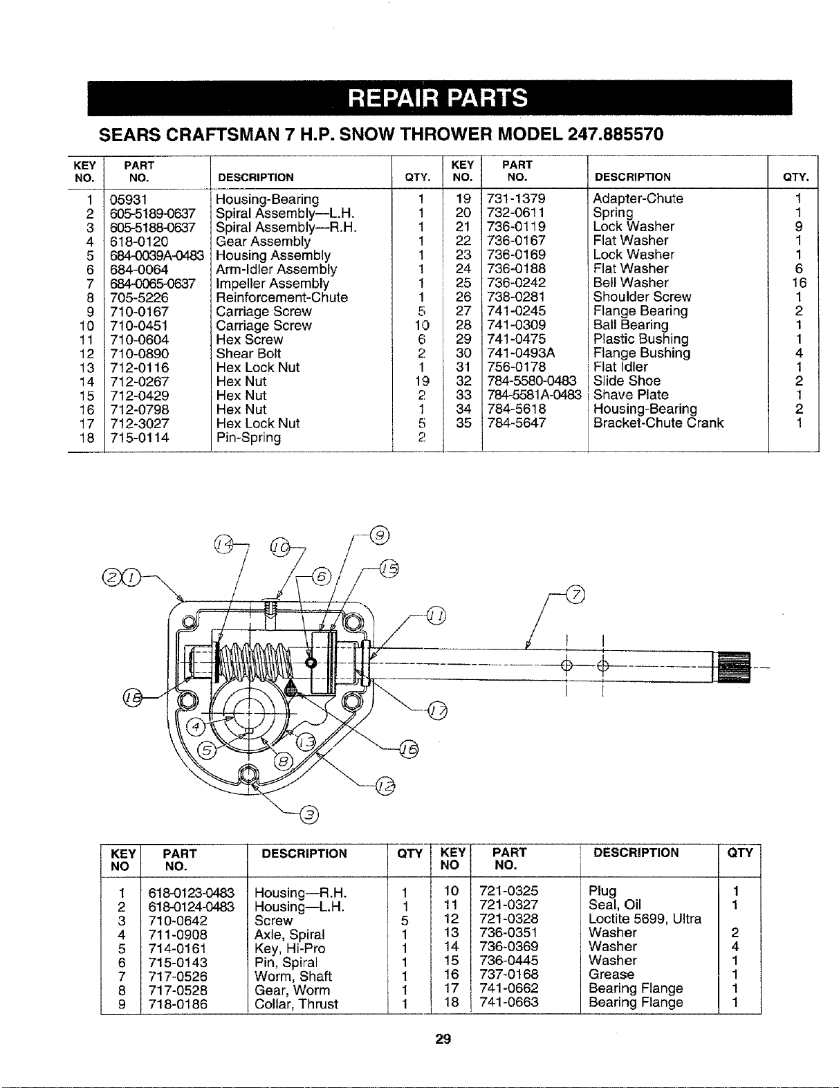
SEARS CRAFTSMAN 7 H,P, SNOW THROWER MODEL 247.885570
KEY PART
NO, NO.
1
2
3
4
5
6
7
8
9
10
11
12
13
14
15
16
17
18
05931
605-5189-0637
605-5188-0637
618-0120
684-0039A-0483
684-0064
684-0065-0637
705-5226
710-0167
710-0451
710-0604
710-0890
712-0116
712-0267
712-0429
712-0798
712-3027
715-0114
I
I DESCRIPTION
i Housing-Bearing
Spiral Assembly--L.H.
Spiral Assembly--R.H.
Gear Assembly
Housing Assembly
Arm-Idler Assembly
Impeller Assembly
Reinforcement-Chute
Carriage Screw
Carriage Screw
Hex Screw
Shear Bolt
Hex Lock Nut
Hex Nut
Hex Nut
Hex Nut
Hex Lock Nut
Pin-Spring
Q1
I KEY
1. NO.
,ii
23
24
25
26
io 27
28
29
2 30
31
32
33
i 34
35
2
PART
NO.
731-1379
732-0611
736-0119
736-0167
736-0169
736-0188
736-0242
738-0281
741-0245
741-0309
741-0475
741-0493A
756-0178
784-5580-0483
784-5581A-0483
784-5618
784-6647
DESCRIPTION
Adapter-Chute
Spring
Lock Washer
Flat Washer
Lock Washer
Flat Washer
Bell Washer
Shoulder Screw
Flange Bearing
Ball Bearing
Plastic Bushing
Flange Bushing
Flat Idler
Slide Shoe
Shave Plate
Housing-Bearing
Bracket-Chute Crank
QTY, I
•4 I
9 I
1 I
1 I
6 I
161
1 I
2 I
1 !
1 J
4 I
4
2 I
t i
2 I
4 I
KEY PART
NO NO.
@
1 618-0123-0483
2 618-0124-0483
3 710-0642
4 711-0908
5 714-0161
6 715-0143
7 717-0526
8 717-0528
9 718-0186
DESCRIPTION
Housing--R.H.
Housing--L.H.
Screw
Axle, Spiral
Key, Hi-Pro
Pin, Spiral
Worm, Shaft
Gear, Worm
Collar, Thrust
QTY
1
1
5
1
1
1
1
!
1
KEY
NO
10
11
12
13
14
15
!6
17
18
I
PART
NO.
721-0325
721-0327
721-0328
736-0351
736-0369
736-0445
737-0168
741-0662
741-0663
i DESCRIPTION QTY
Plug 1
Seal, Oil 1
Loctite 5699, Ultra
Washer 2
Washer 4
Washer 1
Grease 1
Bearing Flange 1
Bearing Flange 1
29
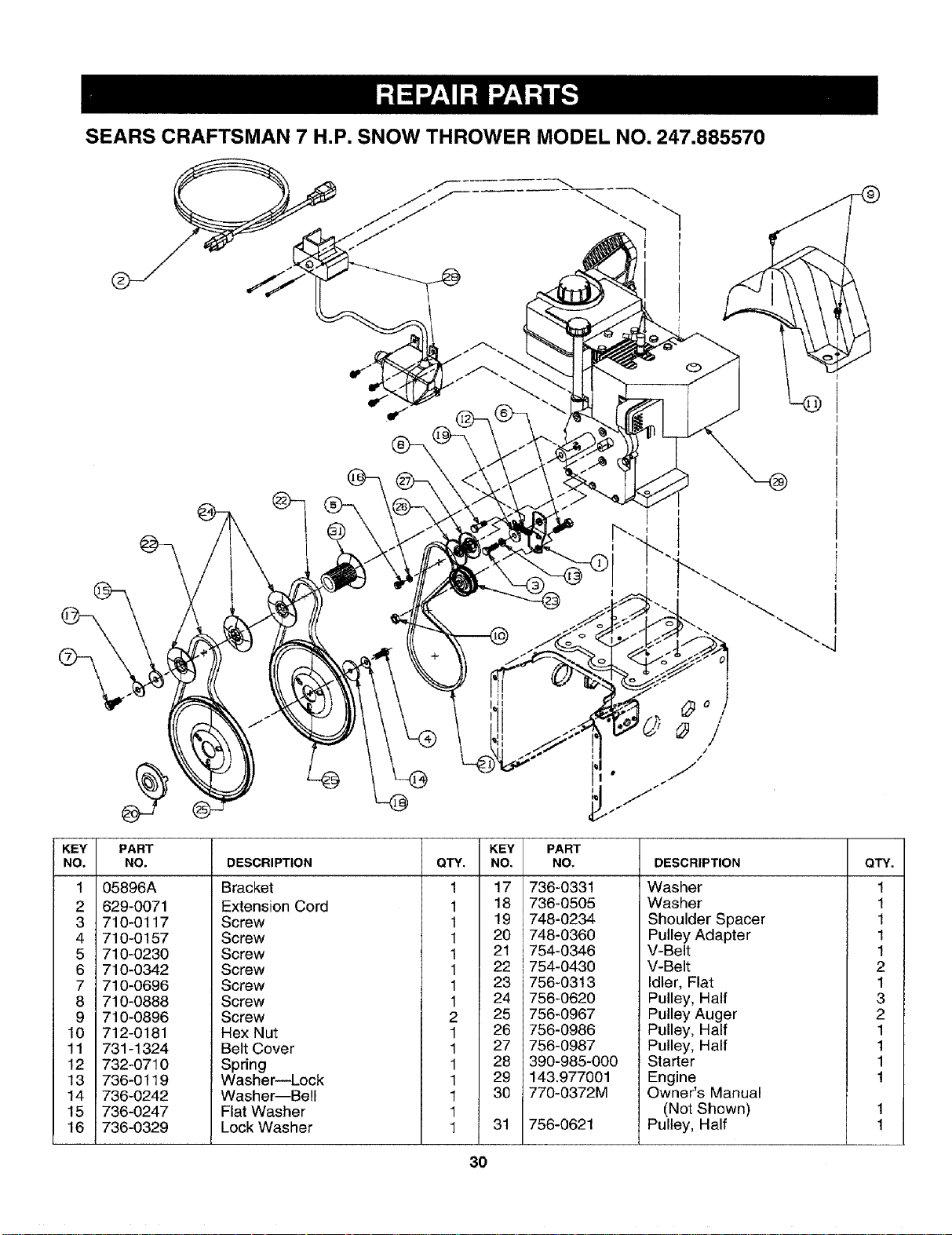
SEARS CRAFTSMAN 7 H.P. SNOW THROWER MODEL NO. 247.885570
/f "--
JJJ
f
KEY
NO.
1
2
3
4
5
6
7
8
9
10
11
12
13
14
15
16
PART
NO.
05896A
629-0071
710-0117
710-0157
710-0230
710-0342
710-0696
710-0888
710-0896
712-0181
731-1324
732-0710
736-0119
736-0242
736-0247
736-0329
DESCRIPTION
Bracket
Extension Cord
Screw
Screw
Screw
Screw
Screw
Screw
Screw
Hex Nut
Belt Cover
Spring
Washer--Lock
Washer--Bell
Flat Washer
Lock Washer
QTY.
1
1
1
1
1
1
1
1
2
1
1
1
1
1
1
1
KEY PART
NO. NO.
17 736-0331
18 736-0505
19 748-0234
20 748-0360
21 754-0346
22 754-0430
23 756-0313
24 756-0620
25 756-0967
26 756-0986
27 756-0987
28 390-985-000
29 143,977001
30 770-0372M
31 756-0621
DESCRIPTION
Washer
Washer
Shoulder Spacer
Pulley Adapter
V-Belt
V-Belt
Idler, Flat
Pulley, Half
Pulley Auger
Pulley, Half
Pulley, Half
Starter
Engine
Owner's Manual
(Not Shown)
Pulley, Half
QTY,
1
1
1
1
1
2
1
3
2
1
1
1
1
1
1
3O
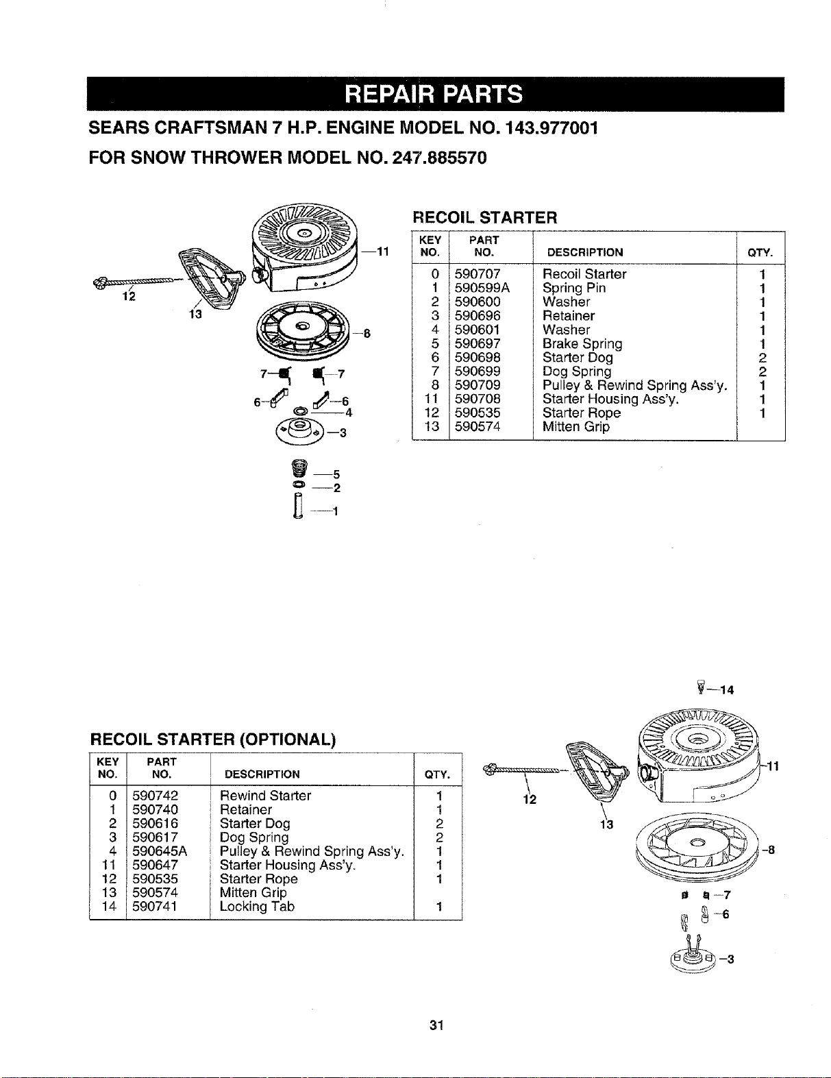
SEARS CRAFTSMAN 7 H.P. ENGINE MODEL NO. 143.977001
FOR SNOW THROWER MODEL NO. 247.885570
___1/3__ -11 0 590707
1 590599A
(__ 2 590600
3 590696
--8 4 590601
5 590697
6 590698
7--_ 1_-7 7 590699
8 590709
6--6_ t:_--_ 11 590708
12 590535
--3 13 590574
_--5
O-- 2
_- -1
RECOIL STARTER
+
KEY PART
NO. NO. DESCRIPTION QTY.
Recoil Starter
Spring Pin
Washer
Retainer
Washer
Brake Spring
Starter Dog
Dog Spring
Pulley & Rewind Spring Ass'y.
Starter Housing Ass'y.
Starter Rope
Mitten Grip
1
1
1
1
1
1
2
2
1
1
1
RECOIL STARTER (OPTIONAL)
DESCRIPTION
KEY PART
NO. NO.
0 590742
1 590740
2 590616
3 590617
4 590645A
11 590647
12 590535
13 590574
14 590741
QTY.
Rewind Starter 1
I Retainer 1
i Starter Dog 2
Dog Spring 2
Pulley & Rewind Spring Ass'y. 1
Starter Housing Ass'y. 1
Starter Rope 1
Mitten Grip
Locking Tab 1
_--14
6--7
31
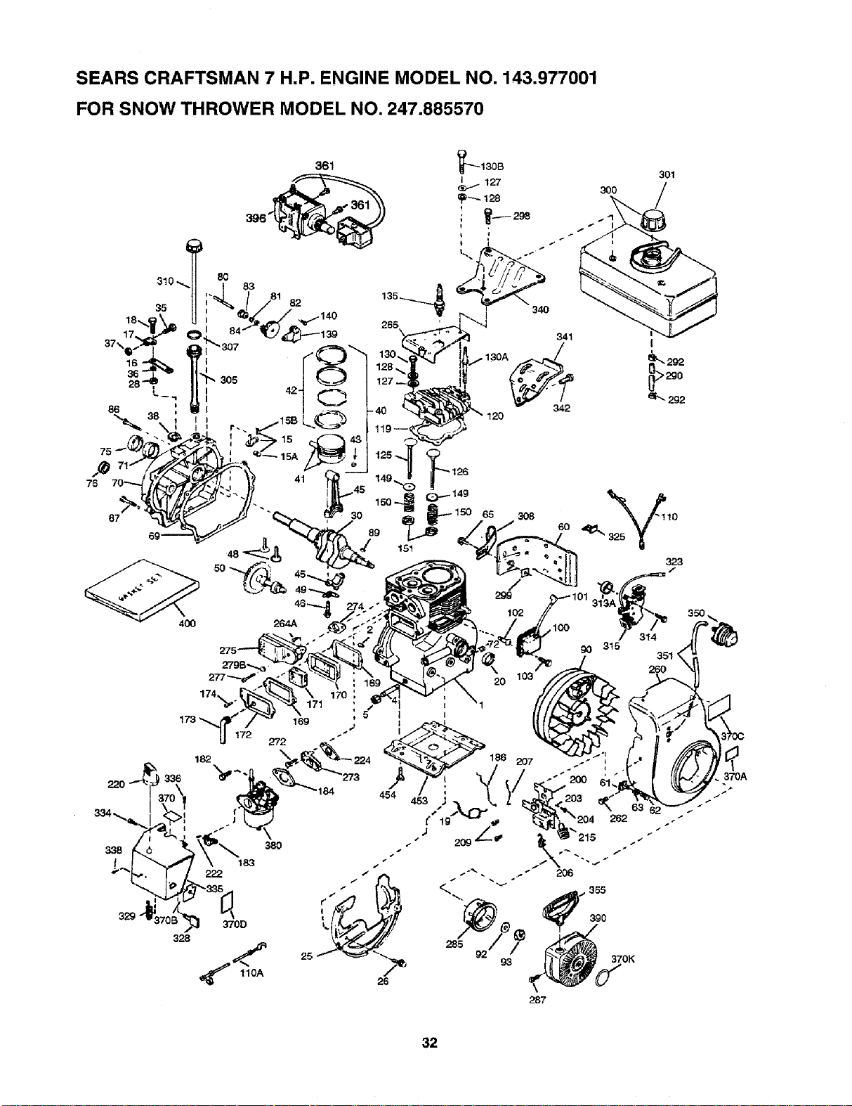
SEARS CRAFTSMAN 7 H.P. ENGINE MODEL NO. 143.977001
FOR SNOW THROWER MODEL NO. 247.885570
I
292
400 264A
174
172
38O
2O
287
370A
J
32
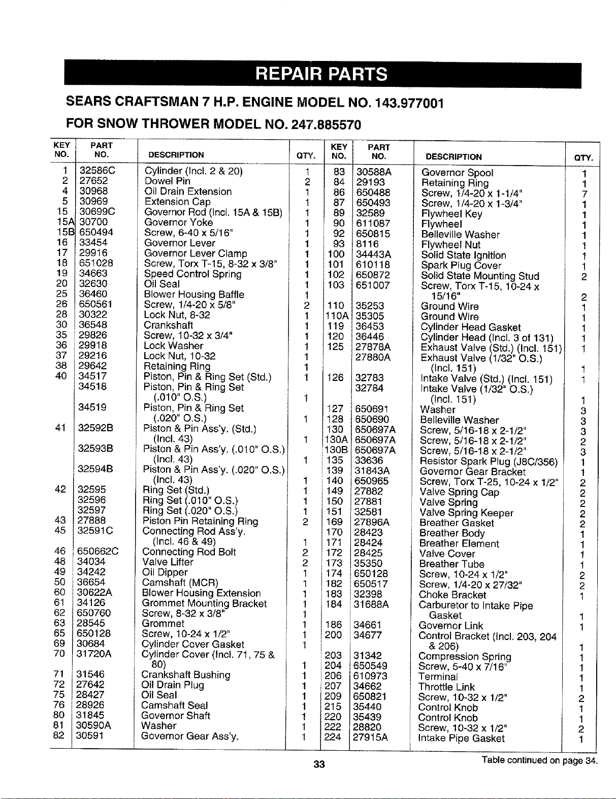
SEARS CRAFTSMAN 7 H.P. ENGINE MODEL NO. 143.977001
FOR SNOW THROWER MODEL NO. 247.885570
KEY
NO. DESCRIPTION
1
2
4
5
15
15A
15B
16
17
18
19
20
25
26
28
30
35
36
37
38
40
41
42
43
45
46
48
49
50
60
61
62
63
65
69
70
71
72
75
76
80
81
82
PART
NO.
32586C
27652
30968
30969
30699C
30700
650494
33454
29916
651028
34663
32630
36460
650561
30322
36548
29826
29918
29216
29642
34517
34518
34519
32592B
32593B
32594B
32595
32596
32597
27888
32591C
650662C
r34034
34242
36654
30622A
34126
650760
28545
650128
30684
31720A
31546
27642
28427
28926
31845
30590A
30591
Cylinder (Incl. 2 & 20)
Dowel Pin
Oil Drain Extension
Extension Cap
Governor Rod (Incl. 15A & 15B)
Governor Yoke
Screw, 6-40 x 5/16"
Governor Lever
Governor Lever Clamp
Screw, Torx T-15, 8-32 x 3/8"
Speed Control Spring
Oil Seal
Blower Housing Baffle
Screw, 1/4-20 x 5/8"
Lock Nut, 8-32
Crankshaft
Screw, 10-32 x 3/4"
Lock Washer
Lock Nut, 10-32
Retaining Ring
Piston, Pin & Ring Set (Std.)
Piston, Pin & Ring Set
(.010" O.S,)
Piston, Pin & Ring Set
(.o2o" o.s.)
Piston & Pin Ass'y. (Std.)
(Incl. 43)
Piston & Pin Ass'y. (.010" O.S.)
(Incl. 43)
Piston & Pin Ass'y. (.020" O.S.)
(Incl. 43)
Ring Set (Std.)
Ring Set (.010" O.S.)
Ring Set (.020" O.S.)
Piston Pin Retaining Ring
Connecting Rod Ass'y.
(Incl. 46 & 49)
Connecting Rod Bolt
Valve Lifter
Oil Dipper
Camshaft (MCR)
Blower Housing Extension
Grommet Mounting Bracket
Screw, 8-32 x 3/8"
Grommet
Screw, 10-24 x 1/2"
Cylinder Cover Gasket
Cylinder Cover (Incl. 71,75 &
80)
Crankshaft Bushing
Oil Drain Plug
Oil Seal
Camshaft Seal
Governor Shaft
Washer
Governor Gear Ass'y.
QTY.
KE_
NO
1 83
2 84
1 86
1 87
1 89
1 9O
1 92
1 93
1 100
1 101
1 102
1 103
1
2 110
1 !10J
1 119
1 120
1 125
1
1
1 126
1
127
1 128
130
1 130A
130B
1 _35
39
1 140
1 149
1 150
1 151
2 169
170
1 !71
2 172
2 173
1 174
1 182
1 183
1 184
1
1 186
1 200
li
i203
_ 204
!206
1 j207
1 209
1 215
1 220
PART
NO.
30588A
29193
650488
650493
32589
611087
650815
8116
34443A
610118
650872
651007
35253
35305
36453
36446
27878A
27880A
32783
32784
650691
650690
650697A
650697A
650697A
33636
31843A
650965
27882
27881
32581
27896A
28423
28424
28425
35350
650128
650517
32398
31688A
34661
34677
31342
650549
610973
34662
650821
35440
35439
28820
27915A
DESCRIPTION
Governor Spool
Retaining Ring
Screw, t/4-20 x 1-1/4"
Screw, I/4-20 x 1-3/4"
Flywheel Key
Flywheel
Belleville Washer
Flywheel Nut
Solid State Ignition
Spark Plug Cover
Solid State Mounting Stud
Screw, Torx T-15, 10-24 x
15/16"
Ground Wire
Ground Wire
Cylinder Head Gasket
Cylinder Head (Incl. 3 of 131)
Exhaust Valve (Std.) (Incl. 151
Exhaust Valve (1/32" O.S.)
(Incl. 151)
Intake Valve (Std.) (Incl. 151)
Intake Valve (1/32" O.S.)
(Incl. 151)
Washer
Belteville Washer
Screw, 5/16-18 x 2-1/2"
Screw, 5/16-18 x 2-1/2"
Screw, 5/16-18 x 2-1/2"
Resistor Spark Plug (J8C/356)
Governor Gear Bracket
Screw, Torx T-25, 10-24 x 1/2"
Valve Spring Cap
Valve Spring
Valve Spring Keeper
Breather Gasket
Breather Body
Breather Element
Valve Cover
Breather Tube
Screw, 10-24 x 1/2"
Screw, 1/4-20 x 27/32"
Choke Bracket
Carburetor to Intake Pipe
Gasket
Governor Link
Control Bracket (Incl. 203, 204
& 206)
Compression Spring
Screw, 5-40 x 7/16
Terminal
Throttle Link
Screw, 10-32 x 1/2"
Control Knob
Control Knob
Screw, 10-32 x 1/2"
Intake Pipe Gasket
Q
2
2
2
1
1
1
1
2
2
1
1
1
1
1
1
2
1
1
2
1
33 Table continued on page 34.

SEARS CRAFTSMAN 7 H.P. ENGINE MODEL NO. 143.977001
FOR SNOW THROWER MODEL NO. 247.885570
Table continued from page 33.
KEY
NO.
260
262
264A
265
272
273
274
275
277
279B
285
287
i290
292
298
299
300
301
305
307
308
310
H3A
314
315
323
325
_28
_29
_34
PART
NO.
35755
29747B
30196
30939A
30196
34712
35865
32401
650694A
26073
35287B
650926
30962
26460
650665
650764
34186A
35355
35554
35499
35540
36205
35189
650873
611111
611118
29443
35593
610973
650257
DESCRIPTION
Blower Housing
Screw, Torx T-40, 5/16-24
x 21/32"
Screw, 5/16-18 x 3/4"
Cylinder Head Cover
Screw, 5/16-18 x 3/4"
Carburetor Flange
Exhaust Manifold Gasket
Muffler
Screw, 5/16-18 x 2"
Washer
Starter Cup
Screw, 8-32 x 21/64"
Fuel Line
Fuel Line Clamp
Screw, 1/4-15 x 3/4"
"U" Type Nut
Fuel Tank (Incl. 292 & 301)
Fuel Cap
Oil Fill Tube
"O" Ring
Fill Tube Clip
Dipstick
Spacer
Screw, 1/4-20 x 3/4"
Alternator Coil (18 Watt)
(Incl. 323)
Terminal
Wire Clip
Ignition Keys
Terminal
Screw, 8-32 x 5/16"
QTY.
1
2
1
1
2
1
1
1
1
1
1
1
1
1
1
1
1
1
1
1
1
1
1
2
1
2
KEY PART
NO, NO.
335 35060
336 650765
338 650760
340 34159
341 134158
342 650561
350 i70682
351 ! 32180C
355 590574
361 650990
370 34414
370A 36261
370B 34418
3700 36501
370D 35063
370K 36695
380 632371A
390 590707
396
4O0
453
454
DESCRIPTION
Carburetor Cover
Screw, 10-32 x 1/2"
Screw, 8-32 x 3/8"
Fuel Tank Bracket
Fuel Tank Bracket
Screw, 1/4-20 x 5/8"
Primer Ass'y.
Primer Line
Starter Handle
Screw, Torx T-30, 1/4-20 x
15/32"
Warning Decal
Instruction Decal
Warning Decal
Primer Decal
Instruction Decal
Starter Decal
Carburetor (Incl. 184)
Rewind Starter
QTY.
1
1
1
1
1
1
1
1
1
4
1
1
1
1
1
1
1
1
(Note: This engine could have been built with 590742
starter. Refer to the design of the rope pulley strength
ribs for part identification. Individual starter parts do
not interchange. Refer to service bulletin number 518.)
33328D Electric Starter Motor
(110 Volt) 1
36454 Gasket Set 1
Incl. part no.'s 27272A (1),
27896A (2), 27915A (1),
30684 (1), 31688A (1),
, 35865 (1), 36453 (1)
36705 Engine Mounting Base 1
650542 Screw, 5/16-18 x 3/4" 4
34
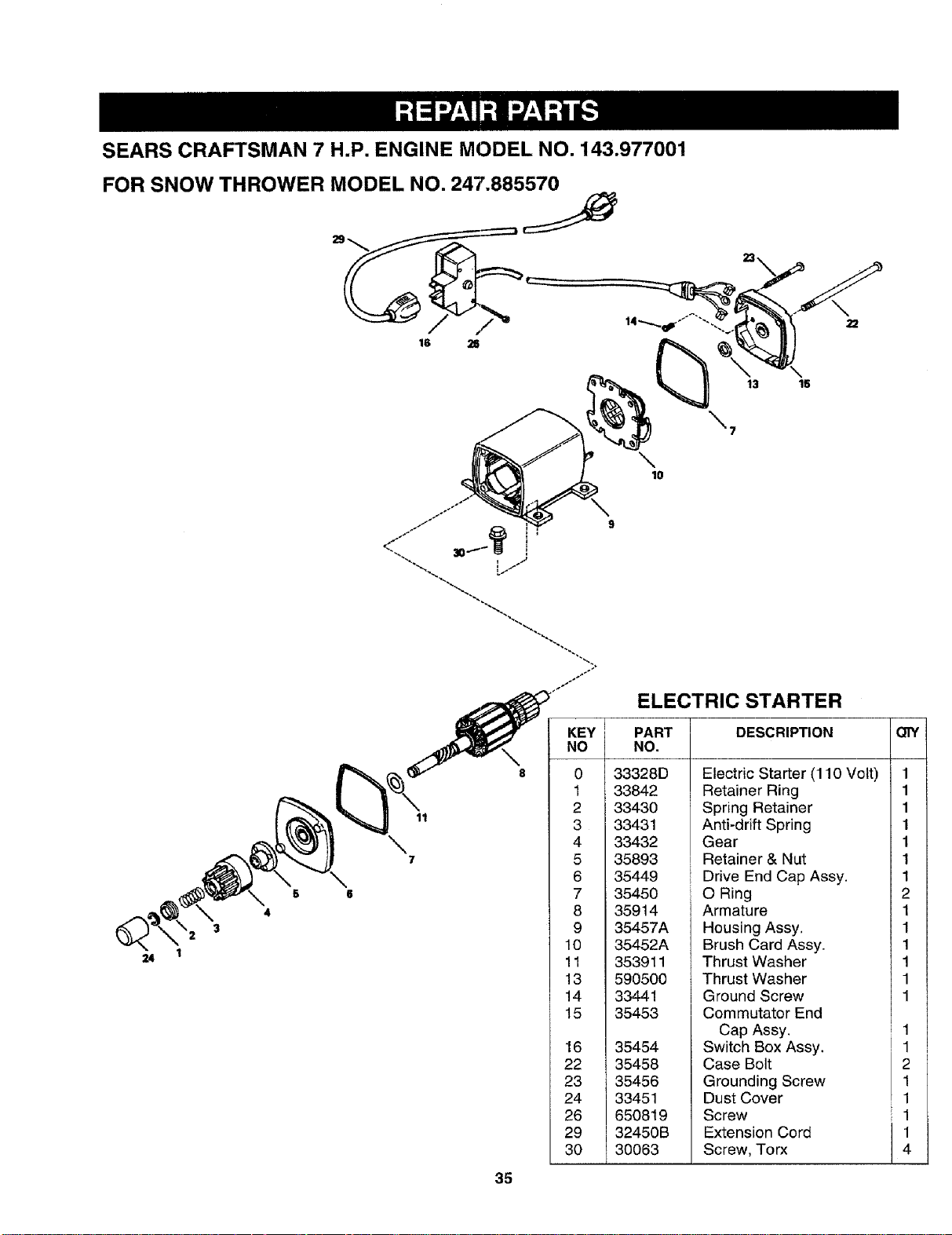
SEARS CRAFTSMAN 7 H.P. ENGINE MODEL NO. 143.977001
FOR SNOW THROWER MODEL NO. 247.885570
13 15
_7
\
lO
24
6
4
11
\
7
35
KEY
NO
8 0
1
2
3
4
5
6
7
8
9
10
11
13
14
15
16
22
23
24
26
29
30
ELECTRIC STARTER
PART DESCRIPTION
NO.
33328D
33842
33430
33431
33432
35893
35449
35450
35914
35457A
35452A
353911
590500
33441
35453
35454
35458
35456
33451
650819
32450B
30063
Electric Starter (110 Volt)
Retainer Ring
Spring Retainer
Anti-drift Spring
Gear
Retainer & Nut
Drive End Cap Assy.
O Ring
Armature
Housing Assy,
Brush Card Assy.
Thrust Washer
Thrust Washer
Ground Screw
Commutator End
Cap Assy.
Switch Box Assy.
Case Bolt
Grounding Screw
Dust Cover
Screw
Extension Cord
Screw, Torx
Q]Y
1
1
1
1
1
1
1
2
1
1
1
1
1
1
1
1
2
1
1
1
1
4
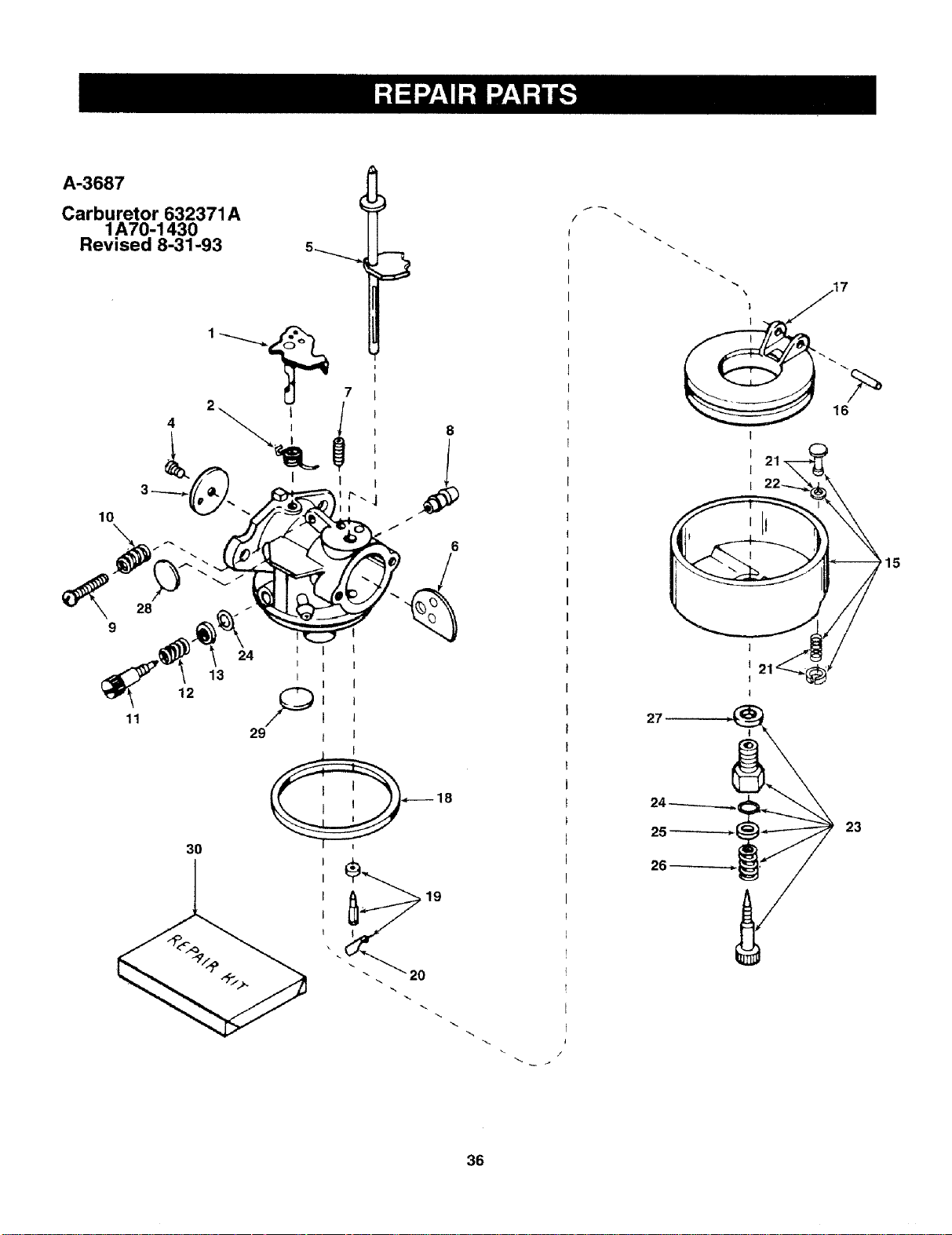
Revised 8-31-93 5_
4
10
\
8
_ .717
>15
27
25
26
23
36
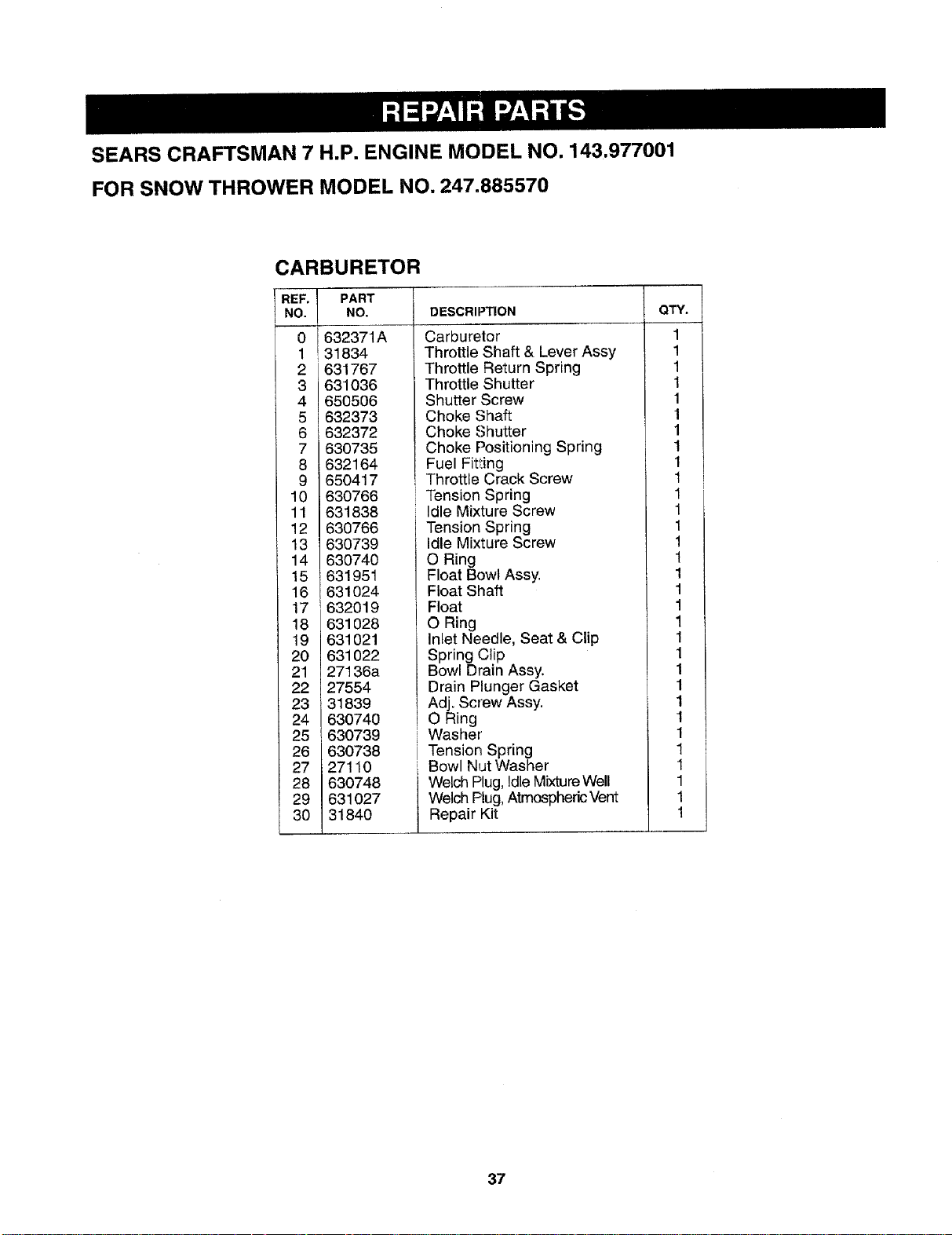
SEARS CRAFTSMAN 7 H.P. ENGINE MODEL NO. 143.977001
FOR SNOW THROWER MODEL NO. 247.885570
CARBURETOR
REF_ I
1
2
3
4
5
6
7
8
9
10
11
12
13
14
15
16
17i
18
19
20
21
22
23
24
25
28
27
28
29
30
PART
NO.
632371A
31834
631767
631036
650506
632373
632372
630735
632164
650417
630766
631838
630766
630739
630740
631951
631024
632019
631028
631021
631022
27136a
27554
31839
630740
630739
630738
27110
630748
631027
31840
DESCRIPTION
Carburetor
Throttle Shaft & Lever Assy
Throttle Return Spring
Throttle Shutter
Shutter Screw
Choke Shaft
Choke Shutter
Choke Positioning Spring
Fuel Fitting
Throttle Crack Screw
Tension Spring
Idle Mixture Screw
Tension Spring
Idle Mixture Screw
O Ring
Float Bowl Assy.
Float Shaft
Float
O Ring
Inlet Needle, Seat & Clip
Spring Clip
Bowl Drain Assy.
Drain Plunger Gasket
Adj. Screw Assy.
O Ring
Washer
Tension Spring
Bowl Nut Washer
Welch Plug,Idle MixtureWell
Welch Plug,Atmospheric Vent
Repair Kit
QTY.
1
1
1
1
1
1
1
1
1
1
1
1
1
1
1
1
1
1
1
1
1
1
1
1
1
1
1
1
37
Fortherepairorreplacementpartsyouneed
delivereddirectlytoyourhome
Call7 am- 7 pm,7 daysa week
1.800.366.PART
(1-800-366-7278)
Forin-homemajorbrandrepairservice
Call24 hoursa day,7 daysa week
1-800-4-REPAIR
(1-800-473-7247)
Forthelocationofa
SearsPartsandRepairCenterinyourarea F_
Call24 hoursaday,7 daysa week [mm
iN
1-800-488-1 222
SEARS
Immmmm
mmmmm|
Forinformationonpurchasinga Sears
MaintenanceAgreementortoinquire
aboutanexistingAgreement
call9am- 5 pm,Monday-Saturday
1-800-827-6655
SEARS
America's Repair Specialists
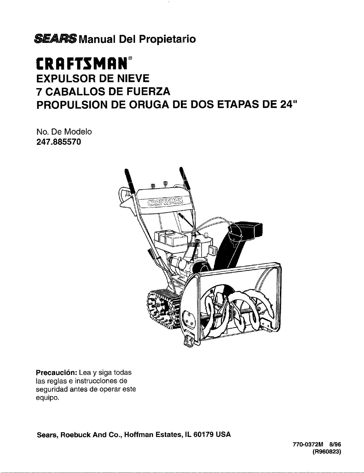
_SManual Del Propietario
CRAFTSMAN°
EXPULSOR DE NIEVE
7 CABALLOS DE FUERZA
PROPULSION DE ORUGA DE DOS ETAPAS DE 24"
No. De Modelo
247.885570
Precauci6n: Lea y siga todas
las regtas e instrucciones de
seguridad antes de operar este
equipo.
Sears, Roebuck And Co., Hoffman Estates, IL 60179 USA
770-0372M 8/96
(R960823)
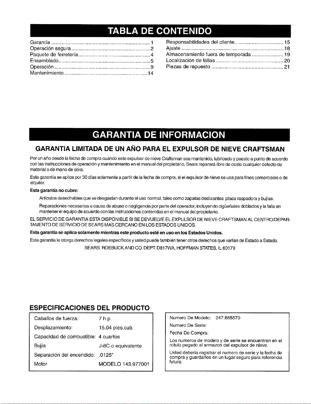
Garant[a ..................................................................... 1
Operacion segura ....................................................... 2
Paquete de ferreterfa .................................................. 4
Ensamblado ................................................................ 5
Operaci6n ................................................................... 9
Mantenimiento .......................................................... 14
Responsabilidades del cliente .................................. 15
Ajuste ....................................................................... 18
Almacenamiento fuera de temporada ...................... 19
Localizacion de fallas ............................................... 20
Piezas de repuesto .................................................. 21
GARANTIA LIMITADA DE UN AgO PARA EL EXPULSOR DE NIEVE CRAFTSMAN
Per una5o desde la fecha de compra cuando este expulsor de nieve Craftsman sea mantenido, lubricado y puesto a punto de acuerdo
con tas instrucciones de operaci6n y mantenimiento en el manual del propietario, Sears reparara libre de costo cualquier defecto de
material ode mane de obra.
Esta garantia se aplica por 30 dfas solamente a partir de la fecha de compra, siel exputsor de nieve se usa para fines comerciales ede
alquiler.
Esta garantia no cubre:
Art_culos desechabtes que se desgastan durante el uso normal, tales come zapatas deslizantes, placa raspadora y bujfas.
Reparaciones necesarias a causa de abuse o negligencia por parte del operador, incluyendo cigOe5ales doblados y lafalla en
mantener el equipo de acuerdo con las instrucciones contenidas en el manual del propietario.
EL SERVICIO DEGARANTIA ESTA DISPONIBLE SI SE DEVUELVE EL EXPULSOR DE NIEVE CRAFTSMAN AL CENTRO/DEPAR-
TAMENTO DE SERVICIO DE SEARS MAS CERCANO EN LOS ESTADOS UNIDOS.
Esta garantia se aplica solamente mientras este producto est_ en uso en los Estades Unidos.
Esta garantia le otorga derechos legales especfficos y usted puede tambien tener otros derechos que varian de Estado a Estado.
SEARS, ROEBUCK AND CO. DEPT. D817WA, HOFFMAN STATES, IL60179
ESPECIFICACIONES DEL PRODUCTO
Caballos de fuerza: 7 h.p.
Desplazamiento: 15.04 pies.cub.
Capacidad de combustible: 4 cuartos
Bujia J-8C o equivalente
Separaci6n del encendido: .0125"
Motor MODELO 143,977001
Numero De Modelo: 247.885570
Numero De Serie:
Fecha De Compra:
Los numeros de modelo y de serie se encuentran en el
rotulo pegado al armazon del expulsor de nieve.
Usted deberia registrar el numero de serie y la fecha de
compra y guardarles en un lugar seguro para referencia
futura.
ESTE SIMBOLO INDICA INSTRUCCIONES IMPORTANTES DE SEGURIDAD LAS CUALES, SI NO SE
SIGUEN, PUEDEN PONER EN PELIGRO LA SEGURIDAD PERSONALY/O LA PROPIEDAD SUYAY
AJENA. ANTES DE INTENTAR OPERAR SU EXPULSOR DE NIEVE LEAY SIGATODAS LAS INSTRUC-
CLONES EN ESTE MANUAL. LA FALTA DE CUMPLIMIENTO CON ESTAS INSTRUCCIONES PUEDE
RESULTAR EN LESIONES PERSONALES.
ADVERTENCIA: Esta unidad est,, equipada con un motor de combusti6n interna y no debe usarse en o cerca de tier-
ras no mejoradas cubiertas de bosques, matorrales, y/o hierbas, a menes que el sistema de escape este equipado
con un supresor de chispas que cumpla con las leyes del estado o federales aplicables (de existir), si se usa un supre-
sor de chispas debe set mantenido en buenas condiciones de trabajo por el operador. En el Estado de California Io
indicado arriba es requerido por ley (Secci6n 4442 del C6digo de Recursos PIJblicos de California). Otros Estados
pueden tener leyes similares. Las leyes federales se aplican en las tierras federales. Esta disponible un supresor de
chispas para el silenciador en su Centre de Servicio Autorizado Sears m&s cercano (Vea la secci6n de PIEZAS DE
REPUESTO de este manual).
ENTRENAMIENTO
• Lea cuidadosamente en su totalidad esta guia del propi-
etario antes de tratar de ensamblar u operar esta
m_tquina. Familiaricese completamente con los con-
troles y el uso correcto de esta mAquina antes de oper-
aria. Mantenga este manual en un lugar seguro para
referencia futura y regular y para ordenar piezas de re-
puesto.
• Nunca permita que nifios menores de 14 afios operen un
expulsor de nieve. Los nifios de 14 afios y mayores de-
ben operar el expulsor de nieve bajo una supervisi6n
paterna estricta. Debe permitirse el uso de su expulsor
de nieve alas personas bien familiarizadas con estas
reglas de operaci6n segura solamente.
• Nadie que este intoxicado o que est6 tomando medici-
nas que debiliten los sentidos o las reacciones debe op-
erar esta unidad.
• Mantenga el _rea de operaci6n despejada de todas las
personas, especialmente nifios pequefios y animales
dom_sticos.
• Sea precavido para evitar resbalar o caer, especial-
mente al operar en marcha de retroceso.
PREPARACION
• Inspeccione completamente el Area donde se usarA el
equipo y retire todos los felpudos, trineos, tablas, ca-
bles y otros objetos extrafios.
• Desenganche todos los embragues y cambie a neutro
antes de arrancar el motor.
• No opere el equipo sin usar ropas externas de invierno
adecuadas. No use joyas, bufandas largas ni otras
ropas holgadas que podr/an enredarse en las piezas
m6viles. Use calzado que mejore la firmeza de su paso
sobre superficies resbaladizas.
• Apague todos los cigarrillos y otras fuentes de encendi-
do, antes de trabajar con gasolina. Inspeccione el com-
bustible antes de arrancar el motor. La gasolina es un
combustible extremadamente inflamable. No Ilene el
tanque de gasolina bajo techo, mientras este funcionan-
do el motor, o hasta que se haya permitido que el motor
se enfrfe durante dos minutos por Io menos. Antes de
arrancar el motor, vuelva a colocar seguramente la tapa
de gasolina y limpie toda la gaselina derramada, ya que
de Io contrario puede causarse un incendio o una ex-
plosi6n.
• Para todas las unidades con motores de propulsion elec-
trica o con motores de arranque et_ctrico use un en-
chufe de tres cables conectado a tierra.
• Ajuste la altura del armaz6n colector para despejar una
superficie de pedregullo o roca triturada.
• Nunca trate de efectuar ajustes mientras el motor esta
funcionando (excepto donde se recomiende especifica-
mente por el fabricante).
Antes de comenzar a despejar la nieve, permita que el
motor y la m_quina se ajusten a la temperatura exterior.
Durante la operaci6n o mientras efect_a un ajuste o rep-
araci6n, use siempre lentes de seguridad o protectores
de ojos, para proteger los ojos contra objetos extrafios
que puedan ser despedidos por la mAquina en cualquier
direcci6n.
OPERACION
• No coloque las manos ni los pies cerca o debajo de pie-
zas giratorias. Mantengase alejado en todo momento de
la abertura de descarga y de la h_lice.
• Sea muy precavido al operar o cruzar sobre entradas de
pedregullo, senderos o caminos. Permanezca alerta
por riesgos ocultos o trY.rico.
• Notransporte pasajeros.
• Despues de golpear un objeto, _pague el motor, extraiga
el cable de la bujia, e inspeccione completamente el ex-
pulsor de nieve pot averias. Antes de volver a arrancar y
operar el expulsor de nieve, repare las aver[as.
• Si el expulsor de nieve comienza a vibrar anormalmente,
apague el motor e inspeccione inmediatamente pot la
causa. La vibraci6n es generalmente una advertencia
de problemas.
• Apague el motor siempre que deje la posici6n operativa,
antes de destapar el armaz6n del colectoripropulsor o la
guia de descarga, y efectuar reparaciones, ajustes, o in-
specciones. Nunca coloque su mane en las aberturas de
descarga o de colecta. Use un palo o un mango de mad-
era de escobill6n para destapar la abertura de descarga.
• Tome todas las precauciones posibles al dejar la unidad
desatendida, Desenganche el colectodpropulsor, cam-
hie e neutro, arranque el motor, y extraiga la Ilave.
• AI limpiar, reparar o inspeccionar, asegL_rese que se
hayan detenido el colector/propulsor y todas laspiezas
m6viles. Desconecte el cable de la bujia y mantengalo
alejado de la buj[a para prevenir un arranque accidental.
• No haga funcionar el motor bajo techo, excepto cuando
arranque el motor y cuando transporte el expulsor de
nieve dentro o fuera del edificio. Abra tas puertas. Los
humos de escape son peligrosos.
• No despeje nieve a trav6s de la superficie de pendi-
entes. At cambiar de direcci6n en las pendientes sea
muy precavido. No intente despejar pendientes muy
pronunciadas.
• Nunca opere el expulsor de nieve sin que las guardas,
ptacas, u otros mecanismos protectores de seguridad,
est_n en su lugar.
• Nunca opere el expuisor de nieve cerca de cerramientos
de vidrio, autom6viles, marcos de las ventanas, caidas,
etc. sin el ajuste correcto del angulo de descarga del ex-
pulsor de nieve. Mantenga alejados a los nifios y a los
animales dom_sticos.
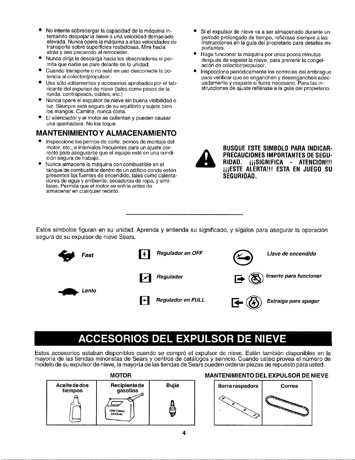
• No intente sobrecargar la capacidad de la mdquina in-
tentando despejar la nieve a una velocidad demasiado
elevada: Nunca opere la m,_quina a altas velocidades de
transporte sobre superficies resbalosas. Mire hacia
atras y sea precavido al retroceder.
• Nunca dirija la descarga hacia los observadores ni per-
mita que nadie se pare delante de la unidad.
• Cuando transporte o no est_ en uso desconecte la po-
tencia a] colector/propulsor.
• Use s61oaditamentos y accesorios aprobados por el fab-
ricante del expulsor de nieve (tales como pesos de la
rueda, contrapesos, cables, etc.)
• Nunca opere el expulsor de nieve sin buena visibilidad o
luz. Siempre est_ seguro de su equilibrio y sujete bien
los mangos. Camine, nunca corra,
• El silenciador y el motor se calientan y pueden causar
una quemadura. No los toque.
MANTENIMIENTO Y ALMACENAMIENTO
• Inspeccione los pernos de corte, pemos de montaje del
motor, etc., a intervalos frecuentes para un ajuste cor-
recto para asegurarse que el equipo est_ en una condi-
ciSn segura de trabajo.
• Nunca almacene la m&quina con combustible en el
tanque de combustible dentro de un edificio donde est_n
presentes las fuentes de encendido, tales como calenta-
dores de agua y ambiente, secadoras de ropa, y simi-
lares. Permita que el motor se enfrie antes de
almacenar en cualquier recinto.
• Si el expulsor de nieve va a ser almacenado durante un
periodo prolongado de tiempo, refi_rase siempre alas
instrucciones en la guia del propietario para detalles im-
portantes.
• Haga funcionar la mAquina por unos pocos minutos
despues de expeler la nieve, para prevenir la congel-
aci6n de colector/propulsor.
• Inspeccfone ped6dicamente los controles del embrague
para verificar que se enganchen y desenganchen adec-
uadamente y reajuste si fuera necesario, Para las in-
strucciones de ajuste refi_rase a la gufa del propietario.
&
BUSQUE ESTE SllYIBOLOPARA INDICAR-
PRECAUCIONES IMPORTANTES DESEGU-
RIDAD. iiiSIGNIFICA ATENCION!!!
iiiESTE ALERTA!!! ESTA EN JUEGO SU
SEGURIDAD.
Estos simbolos figuran en su unidad. Aprenda y entienda su significado, y sfgalos para asegurar la operaci6n
segura de su expulsor de nieve Sears.
Fast [] Regulador en OFF
_] Regulador
Lento
B Regulador en FULL
Llave de encendido
=_ _ Inserte para funcionar
_ _ Extraiga para apagar
Estos accesorios estaban disponibles cuando se compr6 el expulsor de nieve. EstAn tambi@n disponibles en la
mayoria de las tiendas minoristas de Sears y centros de cat&loges y servicio. Cuando usted provea el nemero de
modelo de su expulsor de nieve, la mayoria de las tiendas de Sears pueden ordenar piezas de repuesto para usted.
MOTOR MANTENIMIENTO DEL EXPULSOR DE NIEVE
Aceite de dos
tiempos
Recipientede
gasolina
Bujia Barra raspadora Correa
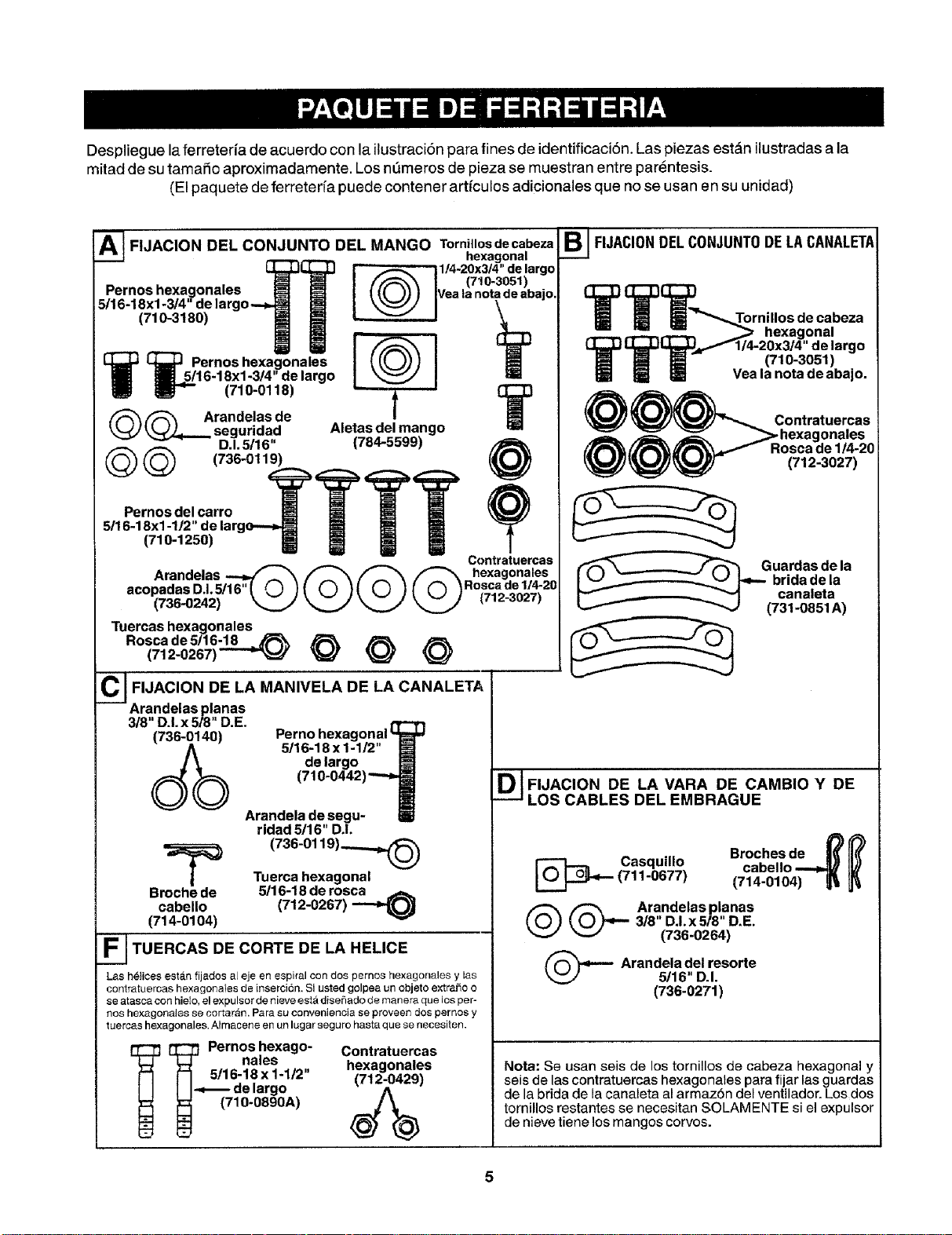
Despliegue laferreterfa de acuerdo con la itustraciTn para fines de identificaci6n. Las piezas est_,n ilustradas a la
mitad de su tamafio aproximadamente. Los mimeros de pieza se muestran entre parentesis.
(El paquete de ferreterfa puede contener artfculos adicionales que no se usan en su unidad)
A__ FIJACION DEL CONJUNTO DEL MANGO Tornillosdecabeza
hexagonal
Pernoshexagonales []_{_ [@ 1/4-20x3t4"delargo(710.3051)
Vea lanotadeabajo.
5/16-18xl-3/4 delargo--_ _ \
_0>mm[ q
[i3q_ Pernos hexagonales
i 5/16-18xl-3/4' de largo
(710-0118) _ [_
_ Arandelas de I
_ seguridad Aletas del mango
D.1.5116" (784-5599)
@@ (736-0119)
(710-1250)8 Ill li Ill
Contratuercas
Arandelas _ _ _ _ hexagonales
acopadasD.L5!16"( © )( © )( © )( © )Ro_c_d#l_20
(736-0242) _ _ _ _ t--=- .... ,
Tuercas hexagonalee __
Rosca de 5/16-18 _
(712-0267) _ @ @ @
CJ FIJACION DE LA MANIVELA DE LA CANALETA
Arandelasplanas
3/8" D.I.x 5/8" D.E.
Perno hexagonal
5/16-18x1-1/2"
de largo
(.
Arandela de segu-
Broche de
cabello
(714-0104)
ridad 5116" D.I.
(736-0119)_
Tuerca hexagonal
5/16-18 de rosca
(712-0267) _
F___ TUERCAS DE CORTE DE LA HELICE
Las h_lices esta.n fijados a[ eje en espiral con dos pernos hexagonales y tas
contratuercas hexagonates de inserci6n. Si usted golpea un objeto extra_o o
se atasca con hielo, el expulsor de nieve esta diseflado de manera que los per-
nos hexagonales se cortaran. Para su conveniencia se proveen dos pernos y
tuercas hexagonales. Almacene en un lugar seguro hasta que se necesiten.
__ Pernos hexago-
nales
['-I 5/16-18 x 1-1/2"
I I_delargo
(710-0890A)
Contratuercas
hexagonales
(712-0429)
e I FIJACIONDELCONJUNTODELACANALETA
,.,.__ ,_ _r nihl/°sd oenCaalbeza
_ U_I,_JF114-2(_4;_ Jargo
i_ Yea la nota de abajo.
_ @_'_ Contrat uercas
_. _>hexagonales
[/'_/1_'_ Rosca de 1/4-20
Ik_/_/ (712-3027)
Guardas de la
brida de la
canaleta
(731-0851 A)
O_OJFIJACION DE LA VARA DE CAMBIO Y DE
LOS CABLES DEL EMBRAGUE
_._ Casquillo Broches de _
(711-0677) cabello ---=_ IV/
(714-0104) |_ lJ_
@ (_., Arandelas planas
3/8" DJ. x 5/8" D.E.
(736-0264)
- Arandela del resorte
5/16" D.I.
(736-0271)
Nota: Se usan seis de los tornillos de cabeza hexagonal y
seis de las contratuercas hexagonates para fijar las guardas
de la brida de la canaleta al armaz6n del ventilador. Los dos
tornillos restantes se necesitan SOLAMENTE si el expulsor
de nieve tiene los mangos corvos.
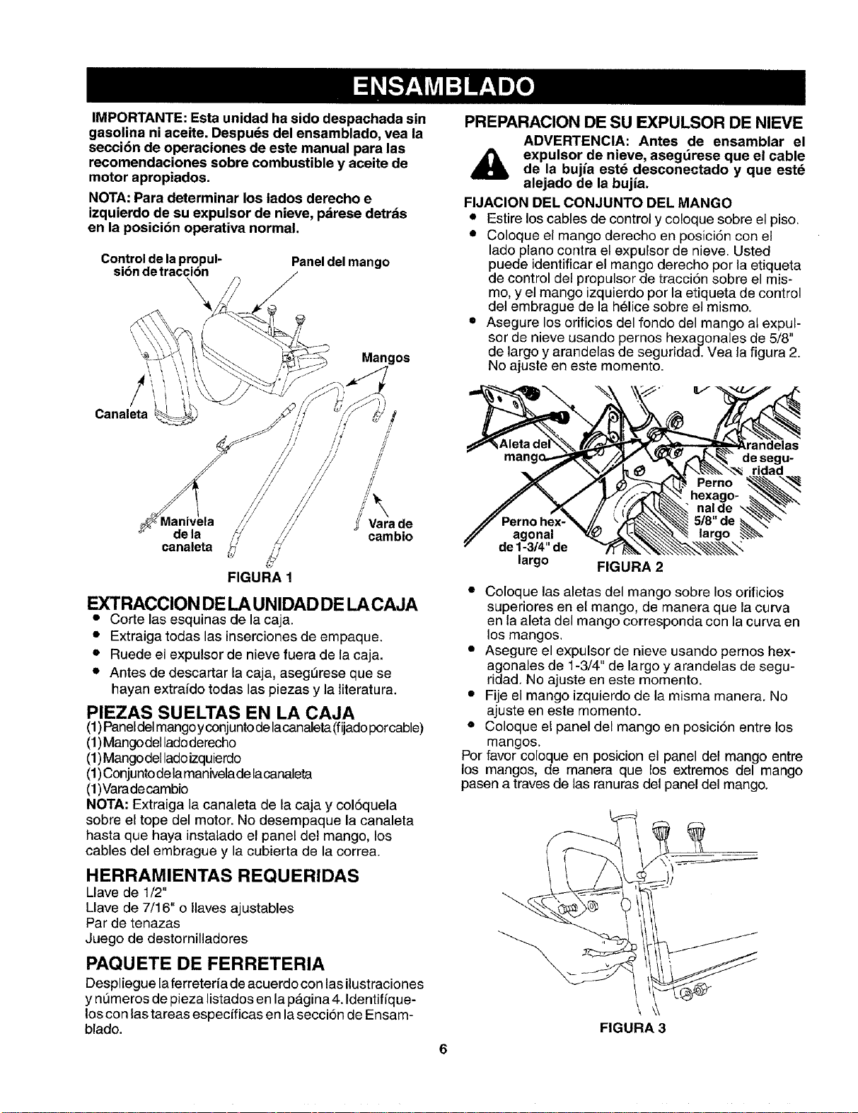
IMPORTANTE: Esta unidad ha side despachada sin
gasolina ni aceite. Despu_s del ensamblado, vea la
secci6n de operaciones de este manual para las
recomendaciones sobre combustible y aceite de
motor apropiados.
NOTA: Para determinar los lados derecho e
izquierdo de su expulsor de nieve, pdrese detr_s
en la posicibn operativa normal.
Controlde lapmpul-
sibndetraccibn
\
Panel del mango
Canaleta
Mangos
//
//
/z
de la
canaleta
_' Vara de
cambio
FIGURA 1
EXTRACCION DE LA UNIDAD DE LA CAJA
• Corte las esquinas de la caja.
• Extraiga todas las inserciones de empaque.
• Ruede el expulsor de nieve fuera de la caja.
• Antes de descartar la caja, aseg_rese que se
hayan extrafdo todas las piezas y la literatura.
PIEZAS SUELTAS EN LA CAJA
(1)Paneldel mangoyconjuntode lacanaleta (fijadoporcable)
(1)Mangodel ladoderecho
(1)Mangodel ladoizquierdo
(1)Conjuntodela manivelade lacanaleta
(1)Varadecambio
NOTA: Extraiga la canaleta de la caja y col6quela
sobre el tope del motor. No desempaque la canaleta
hasta que haya instalado el panel del mango, los
cables del embrague y la cubierta de la correa.
HERRAMIENTAS REQUERIDAS
Llave de 1/2"
Llave de 7/16" o Ilaves ajustables
Par de tenazas
Juego de destornilladores
PAQUETE DE FERRETERIA
Despliegue laferreteria de acuerdo con las ilustraciones
y nt_meros de pieza listados en la p_,gina4. Identifique-
los con las tareas especificas en laseccion de Ensam-
blado.
PREPARACION DE SU EXPULSOR DE NIEVE
ADVERTENCIA: Antes de ensamblar el
expulsor de nieve, asegdrese que el cable
de la bujia estd desconectado y que est_
alejado de la bujia.
FIJACION DEL CONJUNTO DEL MANGO
• Estire los cables de control y coloque sobre el piso.
• Coloque el mango derecho en posici6n con et
lado piano contra el expulsor de nieve. Usted
puede identificar el mango derecho por la etiqueta
de control del propulsor de tracci6n sobre el mis-
mo, y el mango izquierdo por la etiqueta de control
del embrague de la helice sobre el mismo.
• Asegure los orificios del rondo del mango at expul-
sor de nieve usando pernos hexagonales de 5/8"
de largo y arandelas de seguridad. Vea la figura 2.
No ajuste en este momento.
r
Perno hex-
agonal
de 1-3/4" de
largo
FIGURA 2
• Coloque las aletas del mango sobre los orificios
superiores en el mango, de manera que la curva
en la aleta del mango corresponda con la curva en
los mangos.
• Asegure el expulsor de nieve usando pernos hex-
agonales de 1-3/4" de largo y arandelas de segu-
ridad. No ajuste en este momento.
• Fije el mango izquierdo de la misma manera. No
ajuste en este momento.
• Coloque el panel del mango en posici6n entre los
mangos.
Por favor coloque en posicion el panel del mango entre
los mangos, de manera que los extremos del mango
pasen a traves de las ranuras del panel del mango.
6
\
FIGURA 3
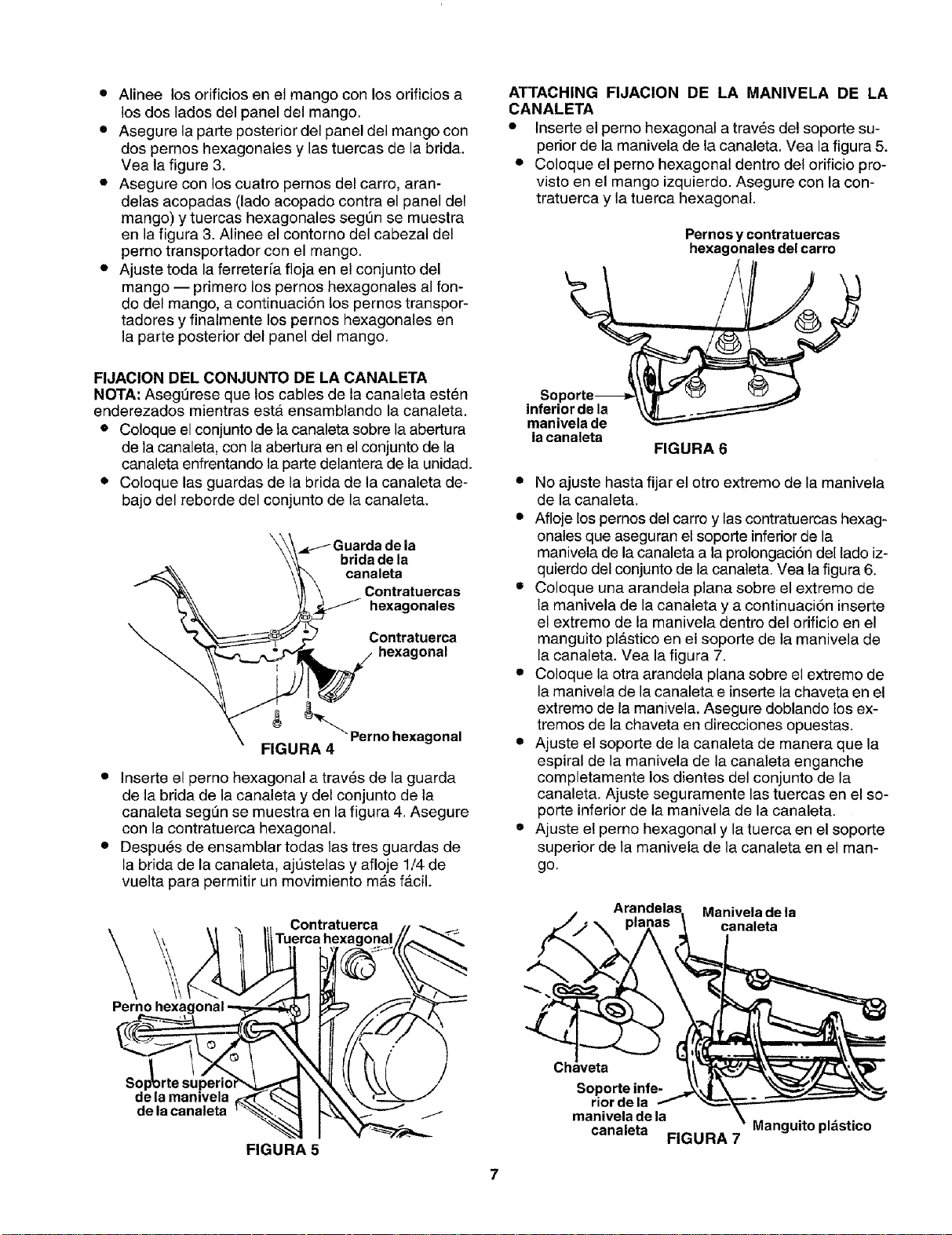
• Alinee los orificios en el mango con los orificios a
los dos lades del panel del mango.
• Asegure la parte posterior del panel dei mango con
dos pernos hexagonales y las tuercas de la brida.
Vea la figure 3.
• Asegure con los cuatro pernos del carro, aran-
delas acopadas (lado acopado contra el panel del
mango) y tuercas hexagonales segt3n se muestra
en la figura 3. Alinee el contorno del cabezal del
perno transportador con el mango.
• Ajuste toda la ferreteri'a floja en el conjunto del
mango -- primero los pernos hexagonales al fort-
do del mango, a continuaciSn los pernos transpor-
tadores y finalmente los pernos hexagonales en
la parte posterior del panel del mango.
FIJACION DEL CONJUNTO DE LA CANALETA
NOTA: Asegt3rese que los cables de la canaleta esten
enderezados mientras estA ensamblando la canaleta.
• Coloque el conjunto de la canaleta sobre la abertura
de la canaleta, con la abertura en el conjunto de la
canaleta enfrentando la parte delantera de la unidad.
• Coloque las guardas de la brida de la canaleta de-
bajo del reborde del conjunto de la canaleta.
_J-- Guarda de la
brida de la
canaieta
Contratuercas
hexagonales
Contratuerca
hexagonal
Pernohexagonal
FIGURA 4
• Inserte el perno hexagonal a trav_s de la guarda
de la brida de la canaleta y del conjunto de la
canaleta segt_n se muestra en la figura 4. Asegure
con la contratuerca hexagonal,
• Despues de ensamblar todas tas tres guardas de
la brida de la canaleta, aj_stelas y afloje 1/4 de
vuelta para permitir un movimiento mAs fAcil.
Perno
Contratuerea
ATTACHING FIJACION DE LA MANIVELA DE LA
CANALETA
• Inserte el pemo hexagonal a trav6s del soporte su-
perior de la manivela de la canaleta, Vea la figura 5.
• Coloque el pemo hexagonal dentro del orificio pro-
visto en el mango izquierdo. Asegure con la con-
tratuerca y la tuerca hexagonal.
Pernos y contratuercas
hexagonales del carro
inferior de la
manivela de
la canaleta
FIGURA 6
• No ajuste hasta fijar el otro extremo de la manivela
de la canaleta.
• Afloje los pemos del carro y las contratuercas hexag-
onales que aseguran el soporte inferior de la
manivela de la canaleta a la prolongaci6n del lado iz-
quierdo del conjunto de la canaleta. Vea la figura 6,
• Coloque una arandeta plana sobre el extremo de
ta manivela de la canaleta y a continuaci6n inserte
el extremo de la manivela dentro del orificio en el
manguito plastico en el soporte de la manivela de
la canaleta. Vea la figura 7.
• Coloque la otra arandela plana sobre el extremo de
la manivela de la canaleta e inserte la chaveta en el
extremo de la manivela. Asegure doblando los ex-
tremes de la chaveta en direcciones opuestas.
• Ajuste el soporte de la canaleta de manera que la
espiral de la manivela de la canaleta enganche
completamente los dientes del conjunto de la
canaleta. Ajuste seguramente las tuercas en el so-
porte inferior de la manivela de la canaleta.
• Ajuste el perno hexagonal y la tuerca en el soporte
superior de la manivela de ta canaleta en el man-
go.
,_,2 Manivela de la
pl canaleta
Sol
de la manivela
de la canaleta
FIGURA 5
O|
Soporte infe-
rior de la
manivela de la
canaleta FIGURA 7
Manguito pldstico
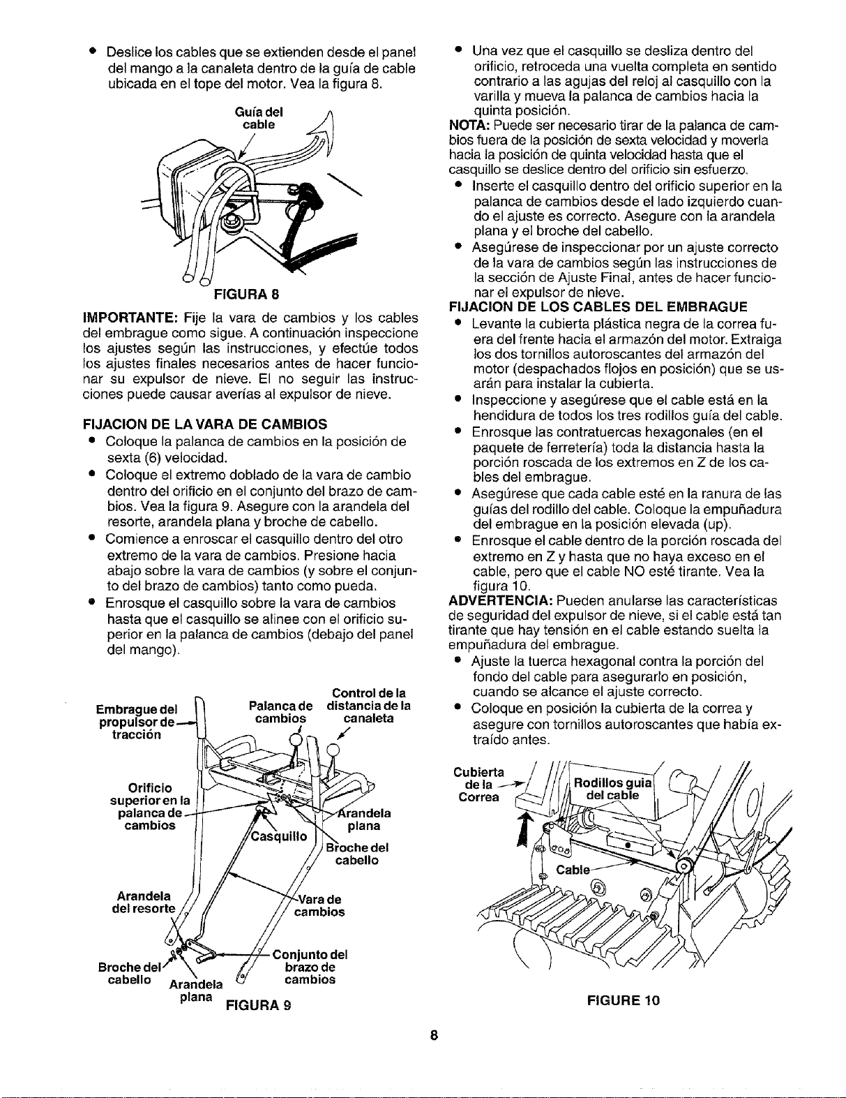
• Deslice los cables que se extienden desde el panel
del mango a la canaleta dentro de la gu[a de cable
ubicada en el tope del motor. Vea la figura 8.
Gu_adel
FIGURA 8
IMPORTANTE: Fije la vara de cambios y los cables
del embrague como sigue. A continuaci6n inspeccione
los ajustes segQn las instrucciones, y efectQe todos
los ajustes finales necesarios antes de hacer funcie-
nar su expulsor de nieve. El no seguir las instruc-
ciones puede causar averfas al expulsor de nieve.
FIJACION DE LA VARA DE CAMBIOS
• Coloque la palanca de cambios en la posici6n de
sexta (6) velocidad.
• Coloque el extremo doblado de la vara de cambio
dentro del orificio en el conjunto del brazo de cam-
bios. Vea la figura 9. Asegure con la arandela del
resorte, arandela plana y broche de cabello.
• Comience a enroscar el casquille dentro del otro
extremo de la vara de cambios. Presione hacia
abajo sobre la vara de cambios (y sobre el conjun-
to del brazo de cambios) tanto como pueda.
• Enrosque el casquillo sobre la vara de cambios
hasta que el casquillo se alinee con el orificio su-
perior en la palanca de cambios (debajo del panel
del mango).
Control de la
Embraauedel _ Palancade distanciadela
propulsorde-_ t cambios canaleta
tracci6n _
Orificio I_""-'---..__..,,_'_ [_"J_.._¢ _
superior en la ! _ _---._'_ IF/
palanca de_ JP_ _._'_>4_,randela
cambios /] i/_as_quillo"_ plana
! I // / JBPochedel
Arandela // // _'_Varade
del resor_ / cambios
,_ _ Conjunto del
Brochedel/ _ _'/ braz.o.de
cabello Arar_dela _/ cambios
plana FIGURA 9
• Una vez que el casquillo se desliza dentro del
orificio, retroceda una vuelta completa en sentido
contrario alas agujas del reloj al casquillo con la
varilla y mueva la palanca de cambios hacia la
quinta posici6n.
NOTA: Puede ser necesario tirar de la palanca de cam-
bios fuera de la posiciSn de sexta velocidad y moverla
hacia la posici6n de quinta velocidad hasta que el
casquillo se deslice dentro del orificio sin esfuerzo.
• Inserte el casquillo dentro del orificio superior en la
palanca de cambios desde el lado izquierdo cuan-
do el ajuste es correcto. Asegure con la arandela
plana y el broche del cabello.
• AsegL_rese de inspeccionar por un ajuste correcto
de la vara de cambies segSn las instrucciones de
la secci6n de Ajuste Final, antes de hacer funcio-
nar el expulsor de nieve.
FIJACION DE LOS CABLES DEL EMBRAGUE
• Levante la cubierta pl_stica negra de la correa fu-
era del frente hacia el armaz6n del motor. Extraiga
los dos tornillos autoroscantes det armaz6n del
motor (despachados fiojos en posici6n) que se us-
ar_n para instalar la cubierta.
• Inspeccione y asegerese que el cable est& en la
hendidura de todes los tres rodillos gu[a del cable.
• Enrosque las contratuercas hexagonales (en el
paquete de ferreterfa) toda la distancia hasta la
porci6n roscada de los extremes en Z de los ca-
bles del embrague.
• AsegL_reseque cada cable est_ en la ranura de las
gufas del rodillo del cable. Coloque la empuSadura
del embrague en la posici6n elevada (up).
• Enrosque el cable dentro de la porci6n roscada del
extremo en Z y hasta que no haya exceso en el
cable, pero que el cable NO est_ tirante. Vea la
figura 10.
ADVERTENCIA: Pueden anularse las caracteristicas
de seguridad del expulsor de nieve, si el cable esta tan
tirante que hay tension en el cable estando suelta la
empuRadura del embrague.
• Ajuste la tuerca hexagonal centra la porci6n del
fondo del cable para asegurarle en pesici6n,
cuando se alcance el ajuste correcto.
• Celoque en posici6n la cubierta de la correa y
asegure con torniltos autoroscantes que habia ex-
traido antes.
Cubierta
Correa
FIGURE 10
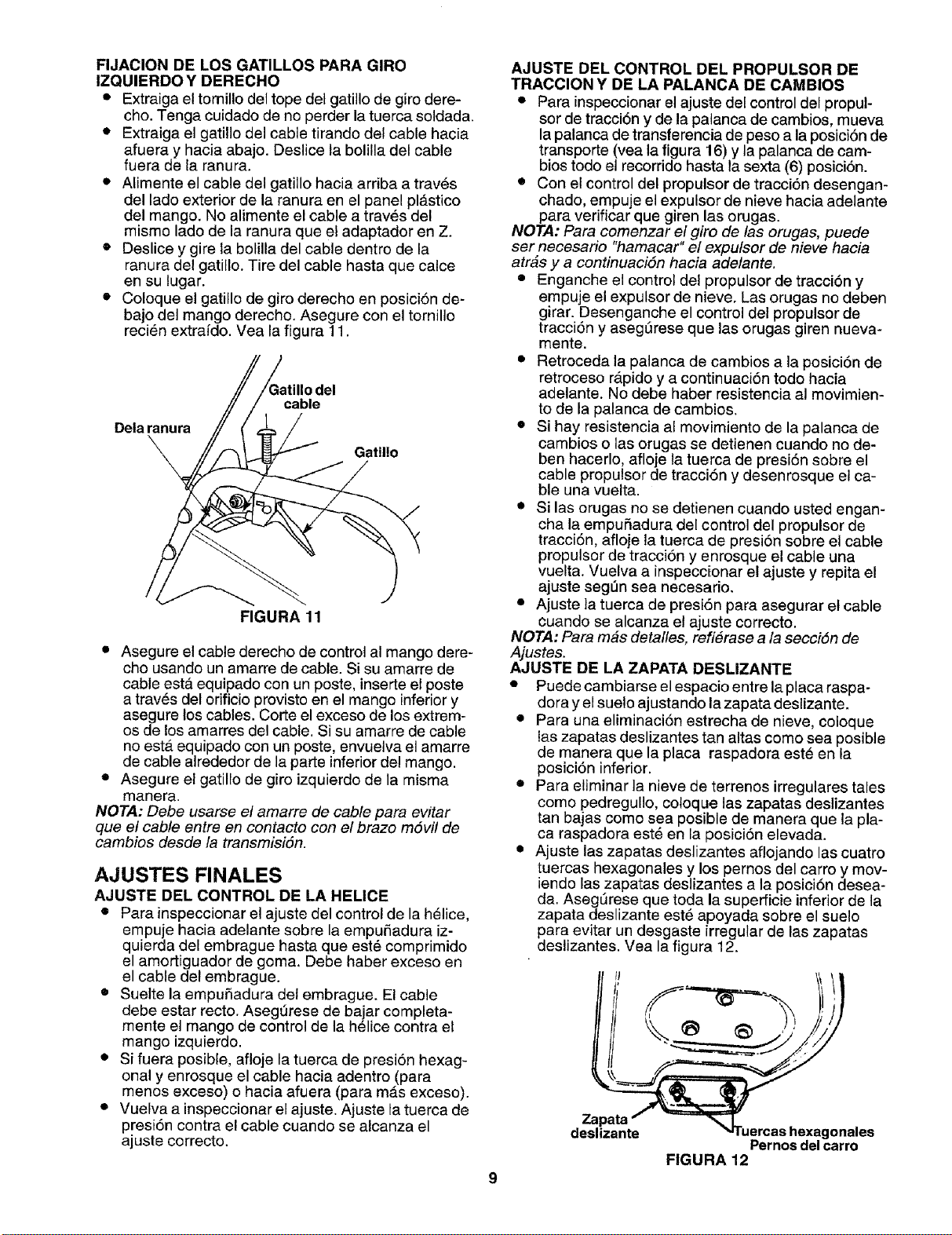
FIJACION DE LOS GATILLOS PARA GIRO
IZQUIERDO Y DERECHO
• Extraiga el tomillo del tope del gatillo de giro dere-
cho. Tenga cuidado de no perder la tuerca soldada.
• Extraiga el gatillo del cable tirando del cable hacia
afuera y hacia abajo. Deslice la bolilla del cable
fuera de la ranura.
• Alimente el cable del gatillo hacia arriba a traves
del lado exterior de la ranura en el panel plAstico
del mango. No alimente el cable a traves del
mismo lado de la ranura que el adaptador en Z.
• Deslice y gire la bolilla del cable dentro de la
ranura del gatillo. Tire del cable hasta que calce
en su lugar.
• Coloque el gatillo de giro derecho en posici6n de-
bajo del mango derecho. Asegure con el tornillo
reci_n extraido. Vea la figura 11.
Delaranura
cable
Gatillo
FIGURA 11
• Asegure el cable derecho de control al mango dere-
cho usando un amarre de cable. Si su amarre de
cable esta equipado con un poste, inserte el poste
a trav6s del orificio provisto en el mango inferiory
asegure los cables. Corte el exceso de los extrem-
os de los amarres del cable. Si su amarre de cable
no est,_equipado con un poste, envuelva el amarre
de cable alrededor de la parte inferior del mango.
• Asegure el gatillo de giro izquierdo de la misma
manera.
NOTA: Debe usarse el amarre de cable para evitar
que el cable entre en contacto con el brazo m6vi! de
cambios desde la transmisiSn.
AJUSTES FINALES
AJUSTE DEL CONTROL DE LA HELICE
• Para inspeccionar el ajuste del control de la helice,
empuje hacia adelante sobre la empuSadura iz-
quierda del embrague hasta que est6 comprimido
el amortiguador de goma, Debe haber exceso en
el cable del embrague.
• Suelte la empuSadura del embrague. El cable
debe estar recto. Asegt3rese de bajar completa-
mente el mango de control de la h_lice contra el
mango izquierdo.
• Si fuera posible, afloje la tuerca de presion hexag-
onal y enrosque el cable hacia adentro (para
menos exceso) o hacia afuera (para mas exceso).
• Vuelva a inspeccionar el ajuste. Ajuste la tuerca de
presi6n contra el cable cuando se alcanza el
ajuste correcto.
AJUSTE DEL CONTROL DEL PROPULSOR DE
TRACCION Y DE LA PALANCA DE CAMBIOS
• Para inspeccionar el ajuste del control del propul-
sor de traccibn y de la palanca de cambios, mueva
la palanca de transferencia de peso a la posiciSn de
transporte (vea la figura 16) y la palanca de cam-
bios todo el recorrido hasta la sexta (6) posici6n.
• Con el control del propulsor de tracci6n desengan-
chado, empuje el expulsor de nieve hacia adelante
para verificar que giren las orugas.
NOTA: Para comenzar el giro de las orugas, puede
ser necesario "hamacar" el expulsor de nieve hacia
atr&s y a continuaciSn hacia adelante.
• Enganche el control del propulsor de tracci6n y
empuje el expulsor de nieve. Las orugas no deben
girar. Desenganche el control del propulsor de
tracciSn y aseg_rese que las orugas giren nueva-
mente.
• Retroceda la palanca de cambios a la posiciSn de
retroceso r_tpido y a continuaciSn todo hacia
adelante. No debe haber resistencia al movimien-
to de la palanca de cambios.
• Si hay resistencia al movimiento de la palanca de
cambios o las orugas se detienen cuando no de-
ben hacerlo, afloje la tuerca de presi6n sobre el
cable propulsor de traccibn y desenrosque el ca-
ble una vuelta.
• Si las orugas no se detienen cuando usted engan-
cha la empu5adura del control del propulsor de
tracci6n, afloje la tuerca de presi6n sobre el cable
propulsor de tracci6n y enrosque el cable una
vuelta. Vuelva a inspeccionar el ajuste y repita el
ajuste seg_n sea necesario.
• Ajuste ta tuerca de presi6n para asegurar el cable
cuando se alcanza el ajuste correcto.
NOTA: Para m_s detalles, refierase a la secci6n de
Ajustes.
AJUSTE DE LA ZAPATA DESLIZANTE
• Puede cambiarse el espacio entre la placa raspa-
dora y el suelo ajustando la zapata deslizante.
• Para una eliminaci6n estrecha de nieve, coloque
las zapatas deslizantes tan altas como sea posible
de manera que la placa raspadora este en la
posici6n inferior.
• Para eliminar la nieve de terrenos irregulares tales
como pedregul!o, cotoque las zapatas deslizantes
tan bajas como sea posible de manera que la pla-
ca raspadora est6 en la posici6n elevada.
• Ajuste las zapatas deslizantes aflojando las cuatro
tuercas hexagonales y los pernos del carro y mov-
iendo las zapatas deslizantes a la posiciSn desea-
da. Asegt_rese que toda la superficie inferior de la
zapata deslizante est_ apoyada sobre el suelo
para evitar un desgaste irregular de las zapatas
deslizantes. Vea la figura 12.
' l!ll
,i ,f
Zapata r _ .
"_rruercashexagonalesdeslizante
Pernosdelcarro
FIGURA 12
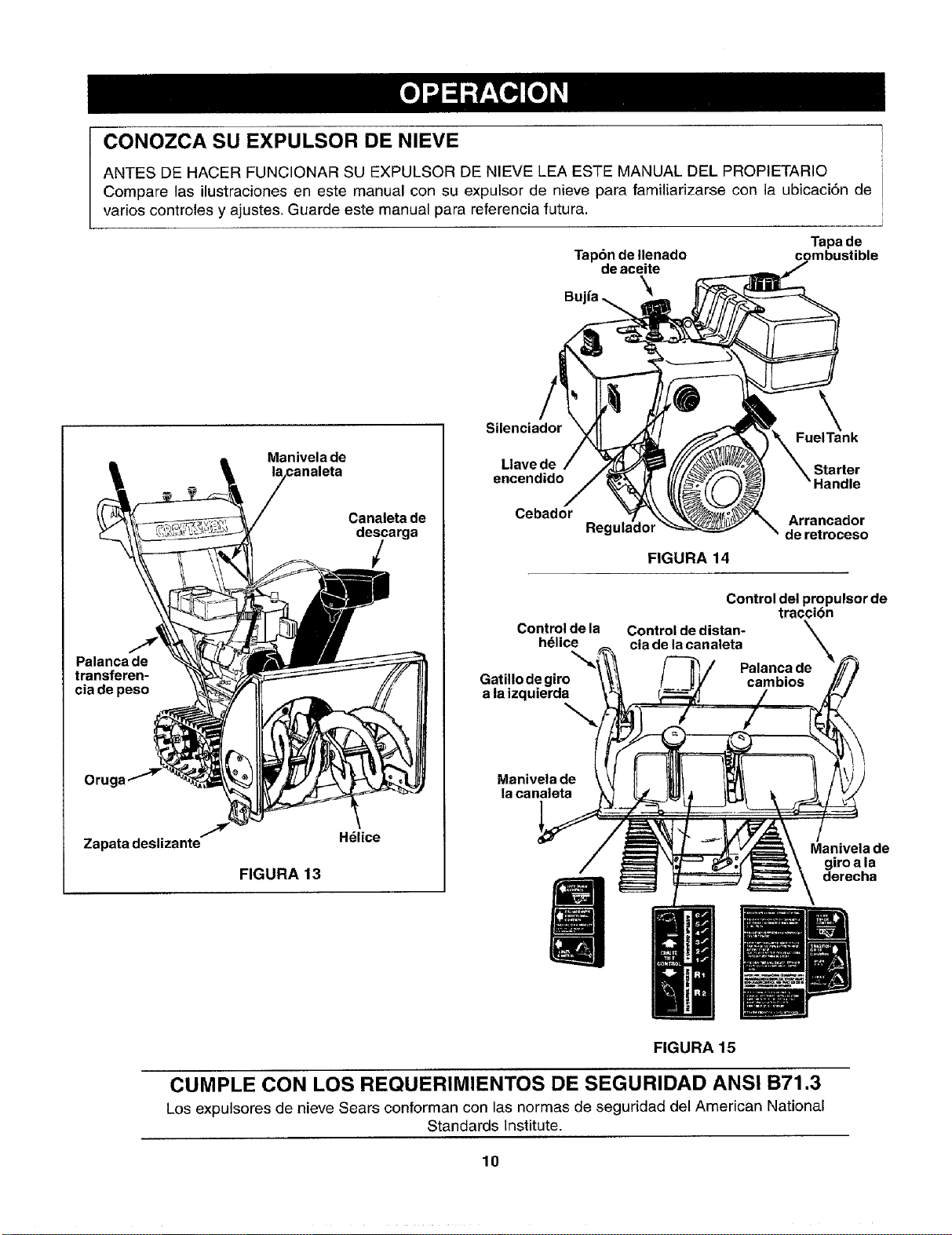
CONOZCA SU EXPULSOR DE NIEVE
ANTES DE HACER FUNCIONAR SU EXPULSOR DE NIEVE LEA ESTE MANUAL DEL PROPIETARIO
Compare las ilustraciones en este manual con su expulsor de nieve para familiarizarse con la ubicaci6n de
varios controles y ajustes. Guarde este manual para referencia futura.
Tapa de
Tap6n de Ilenado
de aceite
Bu.o
Palanca de
transferen-
cia de peso
Oruga
7
Zapata deslizante"
Manivela de
Canaleta de
descarga
/
H_lice
FIGURA 13
Silenciador
Llave de
encendido
Cebador
Control de la
h_lice
\
Gatillo de giro
a la izquierda
Manivela de
la canaleta
FuelTank
Starter
Reg=
FIGURA 14
Arrancador
de retroceso
Control del propulsor de
traccibn
Control de distan-
cia de la canaleta
\
Palanca de
cambios
Manivela de
giro a la
derecha
FIGURA 15
CUMPLE CON LOS REQUERIMIENTOS DE SEGURIDAD ANSI B71.3
Los expulsores de nieve Sears conforman con las normas de seguridad del American National
Standards Institute.
10
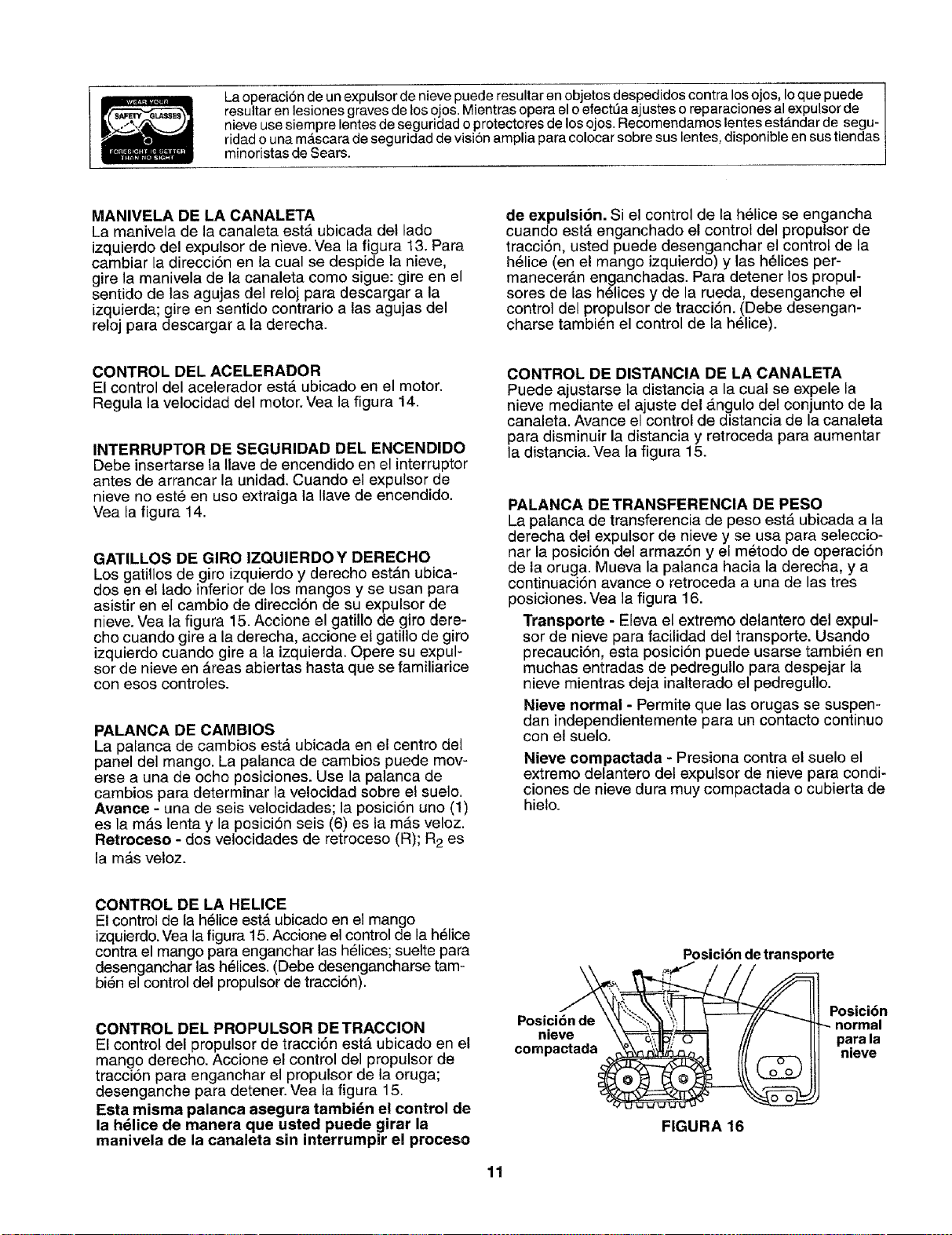
La operaci6n de un expulsor de nieve puede resultar en objetos despedidos contra los ojos, Ioque puede
resultar en lesiones graves de los ojos. Mientras opera el o efect_a ajustes o reparaciones al expulsor de
nieve use siempre lentes de seguridad o protectores de los ojos. Recomendamos tentes est_mdar de segu-
ridad o una mascara de seguridad de visiSn amplia para colocar sobre sus lentes, disponible en sus tiendas
minoristas de Sears.
MANIVELA DE LA CANALETA
La manivela de la canaleta esta ubicada del lado
izquierdo del expulsor de nieve. Vea la figura 13. Pare
cambiar la direcci6n en la cual se despide la nieve,
gire la manivela de la canaleta como sigue: gire en el
sentido de las agujas del reloj pare descargar ala
izquierda; gire en sentido contrario alas agujas del
reloj para descargar ala derecha.
de expulsi6n. Si el control de la h61ice se engancha
cuando estA enganchado el control del propulsor de
tracci6n, usted puede desenganchar el control de la
h61ice (en el mango izquierdo) y las h61ices per-
manecerAn en_anchadas. Para detener los propul-
sores de las helices y de la rueda, desenganche el
control del propulsor de tracciSn. (Debe desengan-
charse tambi_n el control de la h_lice).
CONTROL DEL ACELERADOR
El control del acelerador esta ubicado en el motor.
Regula la velocidad del motor. Vea la figura 14.
INTERRUPTOR DE SEGURIDAD DEL ENCENDIDO
Debe insertarse la Ilave de encendido en el interruptor
antes de arrancar la unidad. Cuando el expulsor de
nieve no est6 en uso extraiga la Ilave de encendido.
Vea la figura 14.
GATILLOS DE GIRO IZQUIERDOY DERECHO
Los gatillos de giro izquierdo y derecho estAn ubica-
dos en el lado inferior de los mangos y se usan para
asistir en el cambio de direcci6n de su expulsor de
nieve. Vea la figure 15. Accione el gatillo de giro dere-
cho cuando gire a la derecha, accione el gatillo de giro
izquierdo cuando gire ala izquierda. Opere su expul-
sor de nieve en Areas abiertas hasta que se familiarice
con esos controles.
PALANCA DE CAMBIOS
La palanca de cambios est,. ubicada en el centro del
panel del mango. La palanca de cambios puede mov-
erse a una de ocho posiciones. Use la palanca de
cambios pare determinar la velocidad sobre el suelo.
Avance - una de seis velocidades; la posici6n uno (1)
es lamAs lenta y la posici6n seis (6) es la mas veloz.
Retroceso - dos velocidades de retroceso (R); R2 es
lamAs veloz.
CONTROL DE DISTANCIA DE LA CANALETA
Puede ajustarse la distancia ala cual se expele la
nieve mediante el ajuste del angulo del conjunto de la
canaleta. Avance el control de distancia de la canaleta
pare disminuir la distancia y retroceda para aumentar
la distancia. Vea la figura 15.
PALANCA DETRANSFERENCIA DE PESO
La palanca de transferencia de peso est& ubicada ala
derecha del expulsor de nieve y se usa pare seleccio-
nar la posici6n del armaz6n y el metodo de operaciSn
de la oruga. Mueva la palanca hacia la derecha, y a
continuaci6n avarice o retroceda a una de las tres
posiciones. Vea la figura 16.
Transporte - Eleva el extrerno delantero del expul-
sor de nieve para facilidad del transporte. Usando
precauci6n, esta posicion puede usarse tambi6n en
muchas entradas de pedregullo para despejar la
nieve mientras deja inalterado el pedregullo.
Nieve normal - Permite que las orugas se suspen-
dan independientemente pare un contacto continuo
con el suelo.
Nieve compactada - Presiona contra el suelo el
extremo delantero del expulsor de nieve para condi-
clones de nieve dura muy compactada o cubierta de
hielo.
CONTROL DE LA HELICE
El control de la h_lice est& ubicado en el mango
izquierdo. Vea la figura 15.Accione el control de la h_lice
contra el mango para enganchar las h_lices; suelte para
desenganchar las h_lices. (Debe desengancharse tam-
bi6n el control del propulsor de traccion).
CONTROL DEL PROPULSOR DE TRACCION
El control del propulsor de tracci6n ester ubicado en el
mango derecho. Accione el control del propulsor de
tracci6n para enganchar el propulsor de la oruga;
desenganche para detener. Vea la figura 15.
Esta misma palanca asegura tambidn el control de
la h_lice de manera que usted puede girar la
manivela de la canaleta sin interrumpir ei proceso
Posici
nieve
compactada
Posicibndetransporte
FIGURA 16
Posici6n
normal
para la
nieve
11
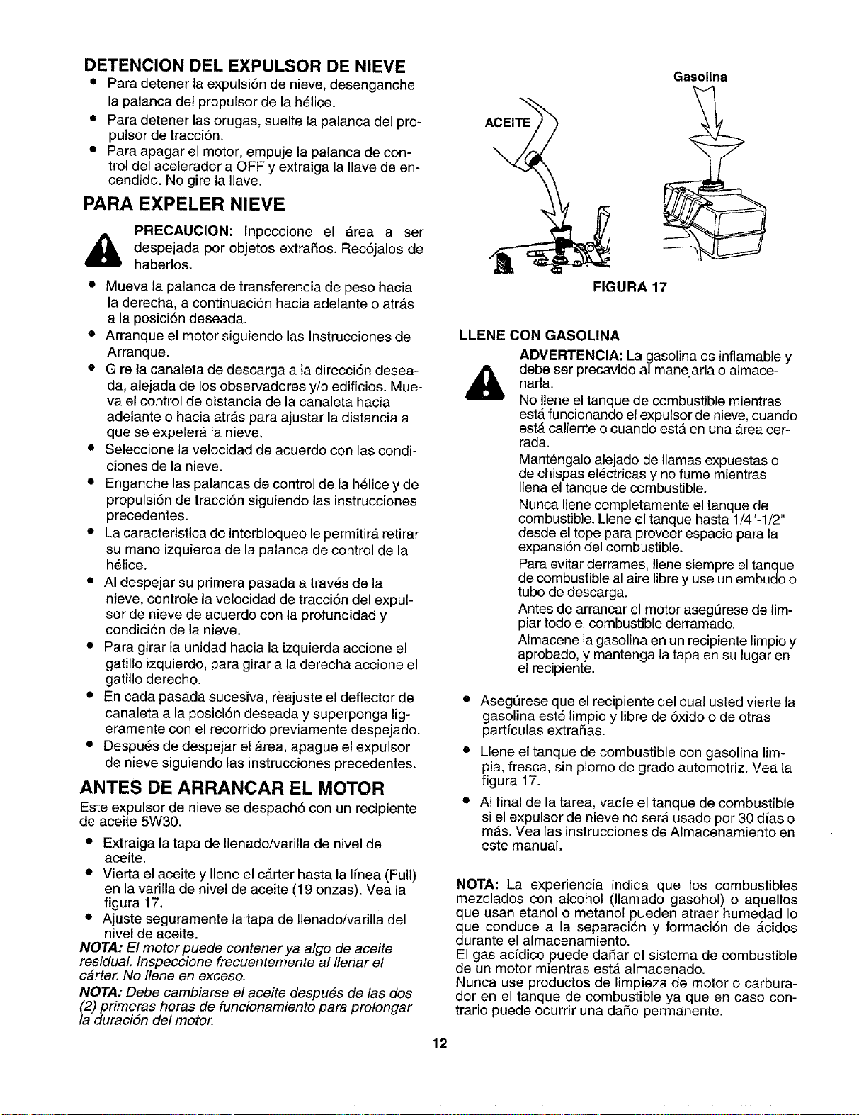
DETENCION DEL EXPULSOR DE NIEVE
• Para detener la expulsi6n de nieve, desenganche
la palanca det propulsor de la h_lice.
• Para detener las orugas, suelte la palanca del pro-
pulsor de tracciSn.
• Para apagar el motor, empuje la palanca de con-
trol del acelerador a OFF y extraiga la Ilave de en-
cendido. No gire la Ilave.
PARA EXPELER NIEVE
PRECAUClON: Inpeccione el Area a ser
despejada por cbjetos extraSos. Rec6jalos de
haberlos.
• Mueva la palanca de transferencia de peso hacia
la derecha, a continuaci6n hacia adelante o atr_ts
a la posici6n deseada.
• Arranque el motor siguiendo las Instrucciones de
Arranque.
• Gire la canaleta de descarga a ta direcci6n desea-
da, alejada de los observadores yio edificios. Mue-
va el control de distancia de la canaleta hacia
adelante o hacia arras para ajustar la distancia a
que se expelerA la nieve.
• Seleccione la velocidad de acuerdo con las condi-
clones de la nieve.
• Enganche las palancas de control de la helice y de
propulsi6n de tracciSn siguiendo las instrucciones
precedentes.
• La caracteristica de interbloqueo le permitirA retirar
su mano izquierda de la palanca de control de la
h_lice.
• AI despejar su primera pasada a trav_s de la
nieve, controle la velocidad de tracci6n del expul-
sor de nieve de acuerdo con la profundidad y
condici6n de la nieve.
• Para girar la unidad hacia la izquierda accione el
gatillo izquierdo, para girar a laderecha accione el
gatillo derecho.
• En cada pasada sucesiva, reajuste el deflector de
canaleta a la posiciSn deseada y superponga lig-
eramente con el recorrido previamente despejado.
• Despu_s de despejar el area, apague el expulsor
de nieve siguiendo las instrucciones precedentes.
ANTES DE ARRANCAR EL MOTOR
Este expulsor de nieve se despach6 con un recipiente
de aceite 5W30.
• Extraiga la tapa de Ilenado/vadlla de nivel de
aceite.
• Vierta el aceite y Ilene el carter hasta la Ifnea (Full)
en la varilla de nivel de aceite (19 onzas). Vea la
figura 17.
• Ajuste seguramente la tapa de llenado/varilla del
nivel de aceite.
NOTA: El motor puede contener ya algo de aceite
residual Inspeccione frecuentemente al Ilenar el
carter. No Ilene en exceso.
NOTA: Debe cambiarse e! aceite despu6s de las dos
(2) primeras horas de funcionamiento para pro!ongar
la duraciSn del motor.
ACEITE
Gasolina
FIGURA 17
LLENE CON GASOLINA
ADVERTENCIA: La gasolina es infiamable y
debe ser precavido al manejarla o almace-
narla.
No Ilene el tanque de combustible mientras
estA funcionando el expulsor de nieve, cuando
estA caliente o cuando esta.en una Area cer-
rada.
Mant_ngalo alejado de llamas expuestas o
de chispas el_ctricas y no fume mientras
Ilena el tanque de combustible.
Nunca Ilene completamente el tanque de
combustible. Llene el tanque hasta 1/4"-1/2"
desde el tope para proveer espacio para la
expansi6n del combustible.
Para evitar derrames, !lene siempre el tanque
de combustible al aire libre y use un embudo o
tubo de descarga.
Antes de arrancar el motor asegt_rese de lim-
piar todo el combustible derramado.
AImacene la gasolina en un recipiente limpio y
aprobado, y mantenga la tapa en su lugar en
el recipiente.
• Asegt3rese que el recipiente del cual usted vierte la
gasolina est6 limpio y libre de 5xido o de otras
partfculas extraSas.
• Llene el tanque de combustible con gasolina lim-
pia, fresca, sin plomo de grado automotriz. Vea la
figura 17.
• AI final de la tarea, vac/e el tanque de combustible
si el expulsor de nieve no serA usado por 30 d[as o
mAs. Vea las instrucciones de Almacenamiento en
este manual.
NOTA: La experiencia indica que los combustibles
mezclados con alcohol (llamado gasohol) o aquellos
que usan etanol o metanol pueden atraer humedad Io
que conduce a la separaci6n y formaci6n de Acidos
durante el almacenamiento.
El gas acfdico puede daRar el sistema de combustible
de un motor mientras esta almacenado.
Nunca use productos de limpieza de motor o carbura-
dot en el tanque de combustible ya que en caso con-
trario puede ocurrir una daSo permanente.
12
PARA ARRANCAR EL MOTOR
(ARRANCADOR ELECTRICO)
Aseg_rese que el motor tiene suficiente aceite. El
motor del expulsor de nieve est,. equipado con un
arrancador el6ctrico de 120 V.C,A. y arrancador de ret-
roceso. El arrancador electrico esta equipado con un
cord6n de tres conductores y un enchufe, y esta dis-
efiado para operar con la corriente casera de 120 volt-
ios de CA. Siga cuidadosamente todas las
instrucciones.
ARRANQUE EN FRIO
NOTA: Si la unidad muestra cualquier indicacidn de
movimiento (proputsor o helices) con las empuSadu-
ras del embrague desenganchadas, apague inmedi-
atamente el motor. Reajuste seg#n se instruye en la
secciSn de "Ajustes Finales" de/as instrucciones de
Ensamblado.
ADVERTENClA: El arrancador debe conec-
tarse correctamente a tierra en todo memento
para evitar la posibilidad de cheque el_ctrico
que puede causar lesiones al operador.
• Determine que el cableado de su casa es un siste-
ma de tres conductores conectado a tierra. Si no
estA seguro, consulte con un electricista licencia-
do.
• Si el sistema de cableado de su casa esta
conectado a tierra y no est,, disponible un re-
cept__culo de tres orificios en el punto en el cual
normalmente se usara el expulsor de nieve, debe
instalarse uno per un electricista licenciado.
ADVERTENCIA: No use este arrancador
electrico bajo ninguna condici6n, si el sistema
de cableado de su casa no es un sistema de
tres conductores conectado a tierra
• AI conectar el cord6n de potencia, conecte siem-
pre primero el cord6n al arrancador del motor, a
continuaci6n enchufe et otro extreme dentro de
un receptaculo de tres orificios conectado a tierra.
• AI desconectar el cord6n de potencia, siempre
desenchufe primero el extreme del recept_culo de
tres orificios conectado a tierra.
• Fije el conductor de la bujfa a la bujfa.
• Asegurese que las palancas del propulsor de la
h_lice y del propulsor de tracci6n esten en la
posici6n desenganchada de RELEASED.
• Mueva la palanca de control del acelerador a la
posici6n FAST.
• Extraiga las Ilaves de la bolsa plastica. Presione la
Ilave dentro de la ranura de encendido. Aseg_rese
que calce en su lugar. NO GIRE LA LLAVE. Man-
tenga la segunda Ilave en un lugar seguro.
• Gire la perilla de] regulador a la posici6n FULL del
regulador.
• Conecte el cord6n de potencia a la caja del inter-
ruptor del motor.
• Enchufe el otro extreme del cord6n de potencia
dentro de un recept_.culo de tres orificios, conecta-
do a tierra de 120 voltios de C.A.
• Presione el bot6n del cebador mientras cubre el
orificio de ventilaci6n come sigue: (Retire el dedo
del bot6n del cebador entre cebados).
No cebe si la temperatura es mayor que 50°E
Cebe dos veces si la temperatura est,_ entre
50-°Fy 15-°F.
Cebe cuatro veces si la temperatura es inferior
a 15°F
• Presione el beton del arrancador hasta que ar-
ranque el motor. No intente arrancar per ma.sde
10 segundos per vez. Este arrancador est& termi-
camente protegido. Si se sobrecalienta, se apa-
gar_. automaticamente y puede arrancarse
nuevamente cuando se haya enfriado a una tem-
peratura segura solamente (se requiere una espe-
ra de 5 a 10 minutes).
• Suelte el bot6n del arrancador y gire lentamente el
regulador a la posici6n OFF, cuando arranca el
motor. Si el motor vacila, gire el regulador a FULL
y a continuaci6n gradualmente a OFF.
• Desconecte primero el cord6n de potencia del re-
cept_.culo y a continuaci6n de la caja del interrup-
ter del motor.
• Permita que el motor se caliente per unos pocos
minutes ya que el motor no desarrellar& su poten-
cia plena hasta que alcance la temperatura de op-
eraci6n.
• Opere el motor con el acelerador a fondo (FAST)
cuando expele nieve.
ARRANQUE EN CALIENTE
• Si est,, arrancando un motor caliente despu_s de
apagarlo, gire el regulador a OFF en lugar de
FULL y no presione el bot6n del cebador.
ARRANQUE DEL MOTOR
(ARRANCADOR DE RETROCESO)
Aseg_rese que e! motor tiene aceite suficiente y que
est_n desenganchadas (sueltas) las palancas del pro-
pulser de la helice y del propulsor de tracci6n.
• Mueva el control del acelerador a la posici6n
FAST.
• Introduzca la Ilave dentro de la ranura del encendi-
do y asegL_rese de que calce en su lugar. No gire
la Ilave. Extraiga la bolsa pl_.stica y mantenga la
segunda Ilave en un lugar seguro.
• Gire el control del regulador a la posici6n FULL del
regulador..
• Mientras cubre el orificio de ventilaci6n, presione
el bot6n del cebador. Retire el dedo del bot6n del
cebador durante cebados.
No cebe si la temperatura es superior a 50-°I=.
Cebe dos veces a temperaturas entre 50°F y
15-_F.
Cebe cuatro veces en temperaturas inferiores a
15-°F.
• Tire rapidamente del mango del arrancador. No
permita que el mango retroceda rapidamente sine
que se enrolle lentamente mientras sujeta firme-
mente el mango de! arrancador.
• A medida que el motor se calienta y comienza a
funcionar uniformemente, gire lentamente la perilla
del regulador a la posici6n OFF. Si el motor vacila,
retome a regulador FULL, a continuaci6n mueva
lentamente a la posici6n OFF del regulador.
13
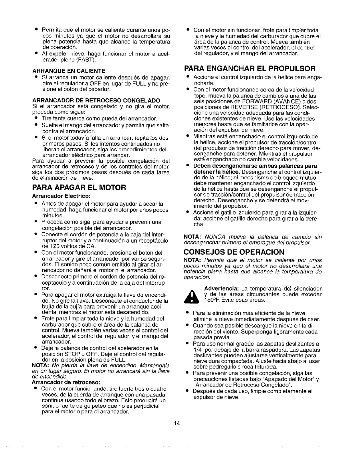
• Permita que el motor se caliente durante unos po-
cos minutes ya que el motor no desarrollara su
plena potencia hasta que alcance la temperatura
de operaci6n.
• AI expeler nieve, haga funcionar el motor a acel-
erador pleno (FAST).
ARRANQUE EN CALIENTE
• Si arranca un motor caliente despu_s de apagar,
gire el regulador a OFF en lugar de FULL y no pre-
sione el bot6n del cebador.
ARRANCADOR DE RETROCESO CONGELADO
Si el arrancador esta congelado y no gira el motor,
proceda come sigue:
• Tire tanta cuerda come pueda del arrancador.
• Suelte el mango del arrancador y permita que salte
contra el arrancador.
• Si el motor todavfa falla en arrancar, repita los dos
primeros pasos. Si los intentos continuados no
liberan el arrancador, siga los procedimientos del
arrancador electrico para arrancar.
Para ayudar a prevenir la posible congelaci6n del
arrancador de retroceso y de los controles del motor,
siga los dos pr6ximos pasos despues de cada tarea
de eliminaci6n de nieve.
PARA APAGAR EL MOTOR
Arrancador Electrico:
• Antes de apagar el motor para ayudar a secar la
humedad, haga funcionar el motor per unos pocos
minutes.
• Proceda come siga, para ayudar a prevenir una
congelaci6n posible del arrancader.
• Conecte el cord6n de potencia a la caja del inter-
ruptor del motor y a continuaci6n a un receptAculo
de 120 voltios de CA.
• Con el motor funcionando, presione el bot6n del
arrancador y gire el arrancador per varies segun-
dos. El sonido poco comt_n emitido al girar el ar-
rancador no dafiara el motor ni el arrancador.
• Desconecte primere el cord6n de potencia del re-
ceptaculo y a continuaci6n de la caja del interrup-
ter.
• Para apagar el motor extraiga la Ilave de encendi-
do. No gire la Ilave. Desconecte el conductor de la
bujia de la bujfa para prevenir un arranque acci-
dental mientras el motor estA desatendido.
• Frete para limpiar toda la nieve y la humedad del
carburador que cubre el Area de la palanca de
control. Mueva tambien varias veces el control del
acelerador, el control del regulador, y el mango del
arrancador.
• Deje la palanca de control del acelerador en la
posici6n STOP u OFF. Deje el control del regula-
dor en la posici6n plena de FULL.
NOTA: No pierda la Ilave de encendido. Mant#ngala
en un lugar seguro. El motor no arrancar# sin la Ilave
de encendido.
Arrancador de retroceso:
• Con el motor funcionando, tire fuerte tres o cuatro
veces, de la cuerda de arranque con una pasada
continua usando todo el braze. Esto producirA un
sonido fuerte de golpeteo que no es perjudicial
para el motor o para el arrancador.
Con el motor sin funcionar, frote para limpiar toda
la nieve y la humedad del carburador que cubre el
_.reade la palanca de control. Mueva tambi6n
varias veces el control del acelerador, el control
del regulador, y el mango del arrancador.
PARA ENGANCHAR EL PROPULSOR
• Accione el control izquierdo de la helice para enga-
ncharla.
• Con el motor funcionando cerca de la velocidad
tope, mueva la palanca de cambios a una de las
seis posiciones de FORWARD (AVANCE) o dos
posiciones de REVERSE (RETROCESO). Selec-
clone una velocidad adecuada para las condi-
clones exJstentes de nieve. Use las velocidades
menores hasta que se familiarice con la eper-
aci6n del expulsor de nieve.
• Mientras esta enganchado el control izquierdo de
la h61ice, accione el propulsor de tracci6n/control
del propulsor de tracci6n derecho para mover, de-
senganche para detener. Mientras el propulsor
estA enganchado no cambie velocidades.
• Deben desengancharse ambas palancas para
detener la hdlice. Desenganche el control izquier-
do de la helice; el mecanismo de bloqueo mutuo
debe mantener enganchado el control izquierdo
de la h61ice hasta que se desenganche el propul-
sor de tracci6n/control del propulsor de traccion
derecho. Desenganche y se detendra el mov-
imiento del propulsor.
• Accione el gatillo izquierdo para girar a la izquier-
da; accione el gatillo derecho para girar a la dere-
cha.
NOTA: NUNCA mueva la palanca de cambio sin
desenganchar primero el embrague del propulsor.
CONSEJOS DE OPERACION
NOTA: Permita que e! motor se caliente per unos
pocos minutes ya que el motor no desarrollar# una
potencia plena hasta que alcance la temperatura de
operacion.
Advertencia: La temperatura del silenciador
y de las Areas circundantes puede exceder
150-°E Evite esas Areas.
• Para la eliminaci6n mas eficiente de la nieve,
elimine la nieve inmediatamente despu6s de caer.
• Cuando sea posible descargue la nieve en la di-
recciSn del viento. Superponga ligeramente cada
pasada previa.
• Para use normal grad_e las zapatas deslizantes a
1/4" per debajo de la barra raspadora. Las zapatas
deslizantes pueden ajustarse verticalmente para
nieve dura compactada. Ajuste hacia abajo al usar
sobre pedregullo o roca triturada.
• Para prevenir una posible congelaci6n, siga las
precauciones listadas bajo "Apagado del Motor" y
"Arrancador de Retroceso Congelado".
• Despu_s de cada use, limpie completamente el
expulsor de nieve.
14
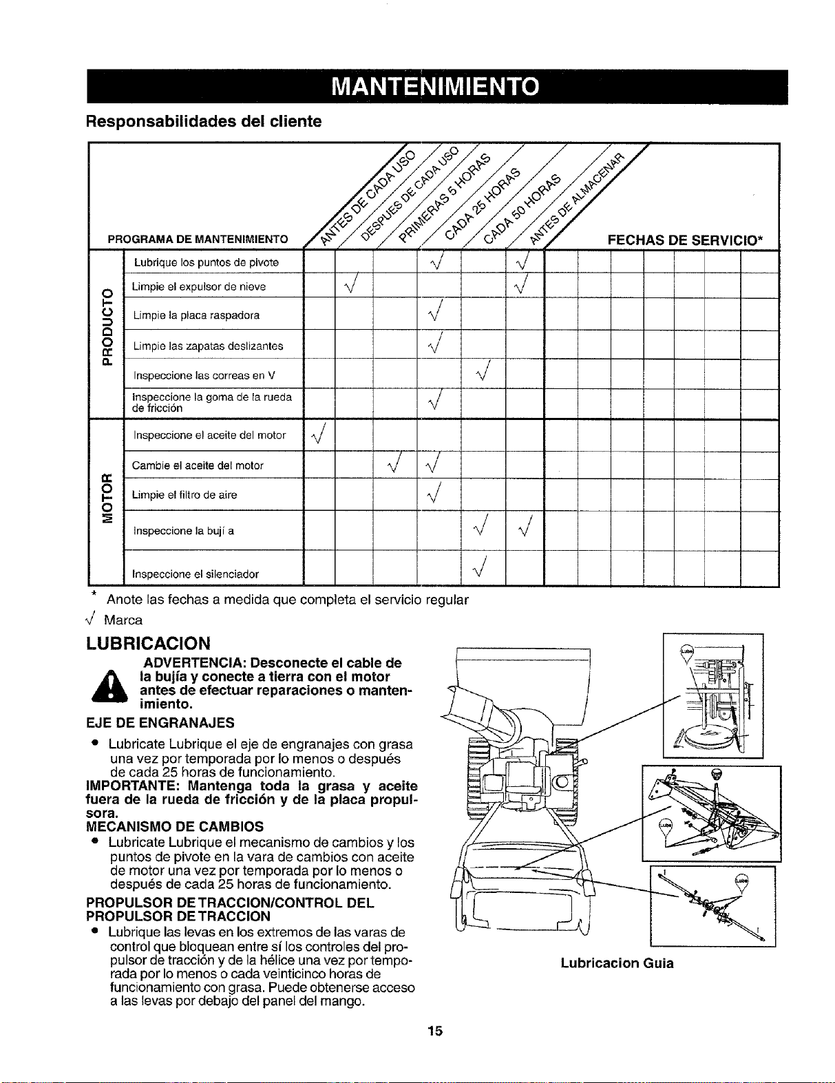
Responsabilidades del cliente
PROGRAMA DE MANTENIMIENTO
Lubrique los puntos de pivote
O Limpie el expulsor de nieve
I-.-
O_ Limpie la placa raspadora
a
o
½,-'%y c.,s
/#/o.,,/,_./o,-/o_..,./#.
,j ,/
J ,/
J
Limpie ]as zapatas deslizantes
Inspeccione las correas en V
Inspecoione la goma de la rueda
de fricci6n
/
,/
/
o
0
Inspeccione el aceite del motor
Cambie el aceite del motor
Limpie el filtro de aire
Inspeccione la buj[ a
,/
DE SERVIClO*
I
I
J
I
i
I
!
I
J
J J I
J
I
Inspeccione el silenciador
_r
Anote las fechas a medida que completa el servicio regular
_/ Marca
LUBRICACION
ADVERTENCIA: Desconecte el cable de
la bujfa y conecte a tierra con el motorantes de efectuar reparaciones o manten-
imiento.
EJE DE ENGRANAJES
• Lubricate Lubrique el eje de engranajes con grasa
una vez por temporada por Io menos o despu_s
de cada 25 horas de funcionamiento.
IMPORTANTE: Mantenga toda la grasa y aceite
fuera de la rueda de friccibn y de la placa propul-
SOFa.
MECANISMO DE CAMBIOS
• Lubricate Lubrique el mecanismo de cambios y los
puntos de pivote en la vara de cambios con aceite
de motor una vez por temporada pot Io menos o
despu_s de cada 25 heras de funcionamiento.
PROPULSOR DETRACCION/CONTROL DEL
PROPULSOR DE TRACClON
• Lubrique las levas en los extremos de las varas de
control que bloquean entre si los controles del pro-
pulsor de tracci6n y de la h61iceuna vez pot tempo-
rada por Io menos o cada veinticinco horas de
funcionamiento con grasa. Puede obtenerse acceso
alas levas por debajo del panel del mango.
Lubricacion Guia
15
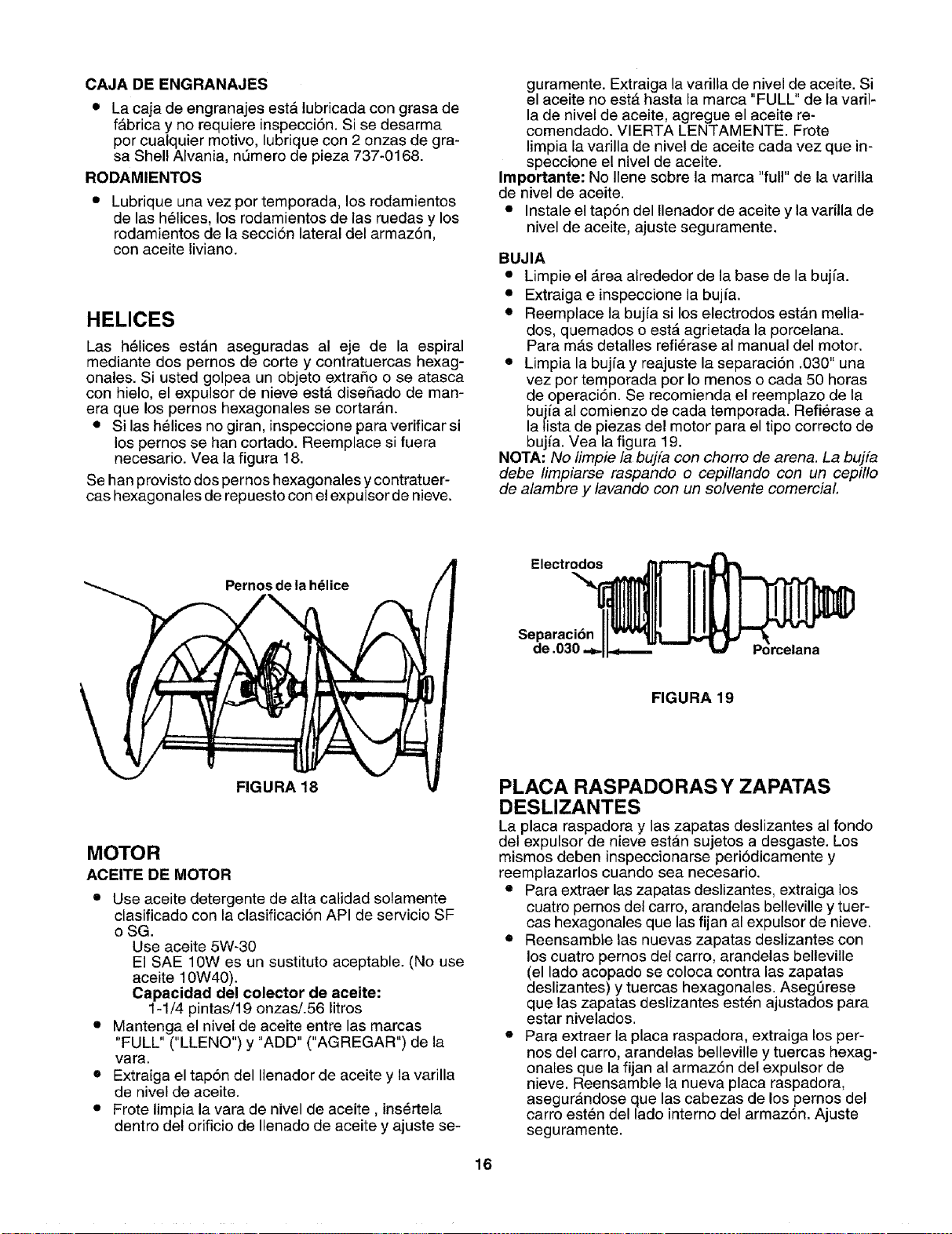
CAJA DE ENGRANAJES
• La caja de engranajes estA lubricada con grasa de
fAbrica y no requiere inspecci6n. Si se desarma
per cualquier motive, lubrique con 2 onzas de gra-
sa Shell Alvania, nL_merode pieza 737-0168.
RODAMIENTOS
Lubrique una vez per temporada, los rodamientos
de las h61ices, los rodamientos de las ruedas y los
rodamientos de la secci6n lateral del armaz6n,
con aceite liviano.
HELICES
Las h61ices estAn aseguradas al eje de la espiral
mediante dos pernos de corte y contratuercas hexag-
onales. Si usted golpea un objeto extraSo o se atasca
con hielo, el expulsor de nieve est_ dise5ado de man-
era que los pernos hexagonales se cortaran.
• Si las hMices no giran, inspeccione para verificar si
los pernos se hart cortado. Reemplace si fuera
necesario. Vea la figura 18.
Se han provisto dos pernos hexagonales y contratuer-
cas hexagonales de repuesto con el expulsor de nieve.
guramente. Extraiga la varilla de nivel de aceite. Si
el aceite no estA hasta la marca "FULL" de la varil-
la de nivel de aceite, agregue el aceite re-
comendado. VIERTA LENTAMENTE. Frote
limpia la varilla de nivel de aceite cada vez que in-
speccione el nivel de aceite.
Irnportante: No Ilene sobre la marca "full" de la varilla
de nivel de aceite.
• Instale el tap6n del Ilenador de aceite y la varilla de
nivel de aceite, ajuste seguramente.
BUJIA
• Limpie el Area alrededor de la base de la bujfa.
• Extraiga e inspeccione la bujfa.
• Reemplace la bujia si los electrodes estAn mella-
dos, quemados o est_ agrietada la porcelana.
Para m_tsdetalles refi_rase al manual del motor.
• Limpia la bujfa y reajuste la separaci6n .030" una
vez per temporada per Io menos o cada 50 horas
de eperaci6n. Se recomienda el reemplazo de la
buj_aal cemienzo de cada temporada. Refierase a
la tista de piezas del motor para el tipo correcto do
buj/a. Vea la figura 19.
NOTA: No limpie la buj[a con chorro de arena. La bujfa
debe limpiarse raspando o cepillando con un cepillo
de alambre y lavando con un solvente comerciaL
Pernos de la hdlice
FIGURA 18
MOTOR
ACEITE DE MOTOR
• Use aceite detergente de alta calidad solamente
clasificado con la clasificacion API de servicio SF
o SG.
Use aceite 5W-30
El SAE 10W es un sustitute aceptable. (No use
aceite 10W40).
Capacidad del colector de aoeite:
1-1/4 pintas/19 onzas/.56 litros
• Mantenga el nivel de aeeite entre las mareas
"FULL" ("LLENO") y "ADD" ("AGREGAR") de la
vara.
• Extraiga el tap6n del Ilenador de aceite y la varilla
de nivel de aceite.
• Frote limpia la vara de nivel de aceite, ins6rtela
dentro del orificio de Ilenado de aceite y ajuste se-
Electrodes
Separaci6n
de .030.
FIGURA 19
PLACA RASPADORAS Y ZAPATAS
DESLIZANTES
La placa raspadora y las zapatas deslizantes al fondo
del expulsor de nieve estan sujetos a desgaste. Los
mismos deben inspeccionarse periodicamente y
reemplazarlos cuando sea necesario.
• Para extraer las zapatas deslizantes, extraiga los
cuatro pernos del carro, arandelas belleville y tuer-
cas hexagonales que las fijan al expulsor de nieve.
• Reensamble las nuevas zapatas deslizantes con
los cuatro pernos del carro, arandelas belleville
(el lade acopado se coloca contra las zapatas
deslizantes) y tuercas hexagonales. Asegt_rese
que las zapatas deslizantes esten ajustados para
estar nivelados.
• Para extraer la placa raspadora, extraiga los per-
nos del carte, arandelas belleville y tuercas hexag-
onales que la fijan al armaz6n del expulsor de
nieve. Reensarnble la nueva placa raspadora,
asegurAndose que las cabezas de los pernos del
carro esten del lade interne del armaz6n. Ajuste
seguramente.
16
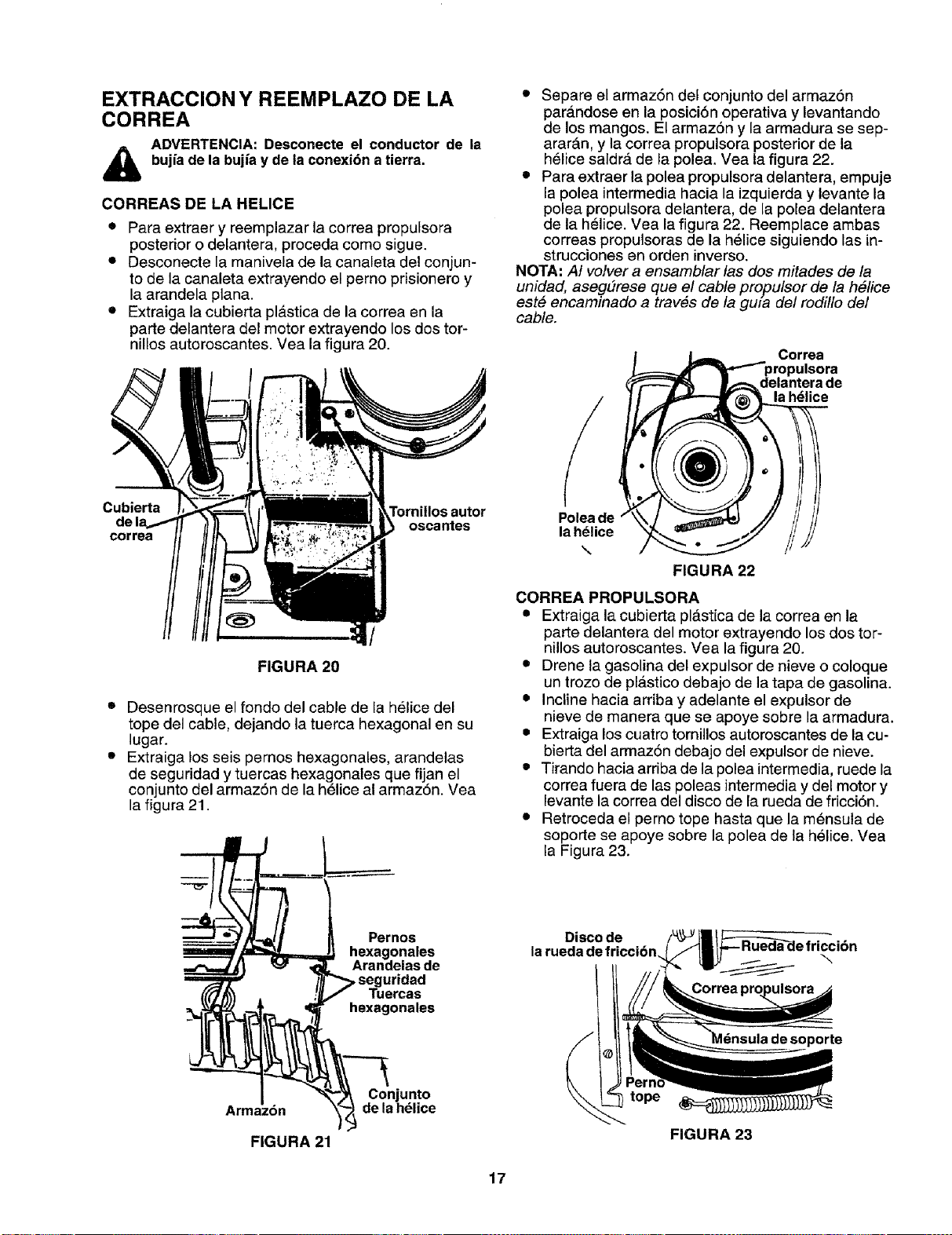
EXTRACCION Y REEMPLAZO DE LA
CORREA
ADVERTENCIA: Desconecte el conductor de la
bujia de la bujia y de la conexi6n a tierra.
CORREAS DE LA HELICE
• Para extraer y reemplazar la correa propulsora
posterior o delantera, proceda como sigue.
• Desconecte la manivela de la canaleta del conjun-
to de la canaleta extrayendo el perno prisionero y
la arandela plana.
• Extraiga la cubierta pl&stica de la correa en la
parte delantera del motor extrayendo los dos tor-
nillos autoroscantes. Vea la figura 20.
• Separe el armaz6n del conjunto del armazbn
para.ndose en la posici6n operativa y levantando
de los mangos. El armazSn y la armadura se sep-
arar&n, y la correa propulsora posterior de la
h_lice saldr_, de la polea. Vea la figura 22.
• Para extraer la polea propulsora delantera, empuje
la polea intermedia hacia la izquierda y levante la
polea propulsora delantera, de la polea detantera
de la helice. Vea la figura 22. Reemplace ambas
correas propulsoras de la helice siguiendo las in-
strucciones en orden inverso.
NOTA" At volver a ensamblar tas dos mitades de ta
unidad, aseg#rese que el cable propulsor de la h#fice
este encaminado a trav#s de ta gma del rodillo del
cable.
Correa
}ulsora
delantera de
la hdlice
Cubierta
de I_
correa
oscantes
/
FIGURA 20
• Desenrosque el fondo del cable de la helice del
tope del cable, dejando la tuerca hexagonal en su
lugar.
• Extraiga los seis pernos hexagonales, arandelas
de seguridad y tuercas hexagonales que fijan el
conjunto del armazSn de la h_lice al armazSn. Vea
la figura 21.
Polea de
la h_lice
\
FIGURA 22
CORREA PROPULSORA
• Extraiga la cubierta plastica de la correa en la
parte delantera del motor extrayendo los dos tor-
nillos autoroscantes. Vea la figura 20.
• Drene la gasolina del expulsor de nieve o coloque
un trozo de plastico debajo de la tapa de gasolina.
• Incline hacia arriba y adelante el expulsor de
nieve de manera que se apoye sobre la armadura.
• Extraiga los cuatro tornillos autoroscantes de la cu-
bierta del armaz6n debajo del expulsor de nieve.
• Tirando hacia arriba de la polea intermedia, ruede la
correa fuera de las poleas intermedia y del motor y
levante la correa del disco de la rueda de fricci6n.
• Retroceda el perno tope hasta que la mensula de
soporte se apoye sobre la polea de la helice. Vea
la Figura 23.
Armazdn
FIGURA21
Pernos
hexagonales
Arandelas de
pseguridad
Tuercas
hexagonales
Conjunto
dela h_lice
FIGURA 23
\
soporte
17
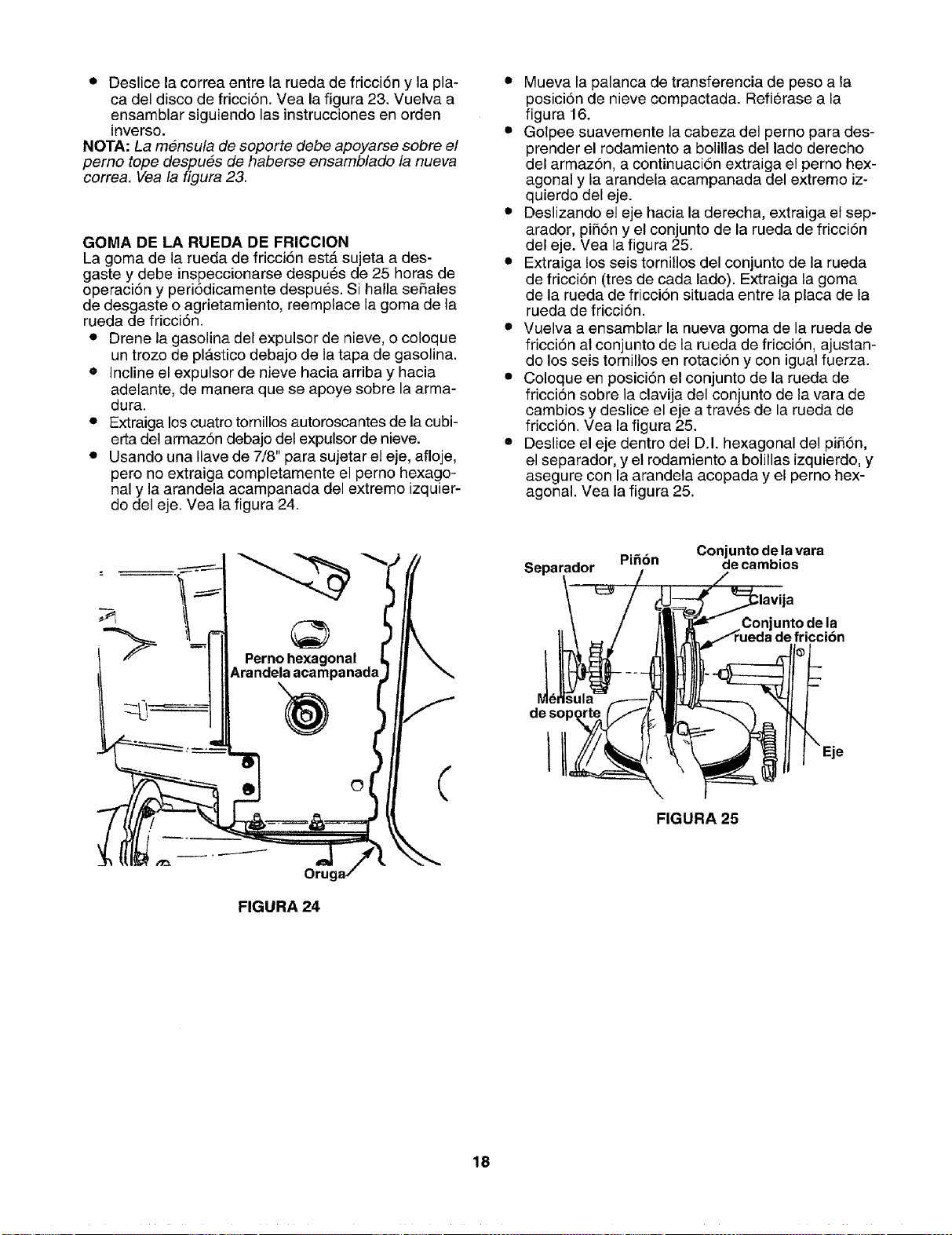
• Deslicelacorreaentrelaruedadefricci6nylapla-
cadeldiscodefricci6n.Vealafigura23.Vuelvaa
ensamblarsiguiendolasinstruccionesenorden
inverso.
NOTA:La mensula de soporte debe apoyarse sobre el
pemo tope despu#s de haberse ensamblado la nueva
correa. Vea la figura 23.
GOMA DE LA RUEDA DE FRICCION
La goma de la rueda de fricci6n est_ sujeta a des-
gaste y debe inspeccionarse despu_s de 25 horas de
operaci6n y peri6dicamente despu_s. Si halla se5ales
de desgaste o agrietamiento, reemplace la goma de la
rueda de fricci6n.
• Drene la gasolina del expulsor de nieve, o coloque
un trozo de plastico debajo de la tapa de gasolina.
• Incline el expulsor de nieve hacia arriba y hacia
adelante, de manera que se apoye sobre la arma-
dura.
• Extraiga los cuatro tornillos autoroscantes de la cubi-
erta del armaz6n debajo del expulsor de nieve.
• Usando una Ilave de 7/8" para sujetar el eje, afloje,
pero no extraiga completamente el perno hexago-
nal y la arandela acampanada del extremo izquier-
do del eje. Vea la figura 24.
• Mueva la palanca de transferencia de peso a la
posici6n de nieve compactada. Refierase a la
figura 16.
• Golpee suavemente la cabeza del perno para des-
prender el rodamiento a bolillas de! lade derecho
del armaz6n, a continuaci6n extraiga el perno hex-
agonal y la arandela acampanada del extremo iz-
quierdo del eje.
• Deslizando el eje hacia la derecha, extraiga el sep-
arador, pi56n y el conjunto de la rueda de fricci6n
del eje. Vea la figura 25.
• Extraiga los seis tornillos del conjunto de la rueda
de fricci6n (tres de cada lado). Extraiga la goma
de la rueda de fricci6n situada entre la placa de la
rueda de fricci6n.
• Vuelva a ensamblar la nueva goma de la rueda de
fricci6n al conjunto de la rueda de fricci6n, ajustan-
do los seis tornillos en rotacion y con igual fuerza.
• Coloque en posici6n el conjunto de la rueda de
fricci6n sobre la clavija del conjunto de la vara de
cambios y deslice el eje a trav_s de la rueda de
fricci6n. Vea la figura 25.
• Deslice el eje dentro del D.I. hexagonal del pi56n,
el separador, y el rodamiento a bolillas izquierdo, y
asegure con la arandela acopada y el perno hex-
agonal. Vea la figura 25.
Oru(
FIGURA 24
¢
Separador
de sop,
Conjunto de la vara
Pi_bn de cambios
Conjunto de la
FIGURA 25
18
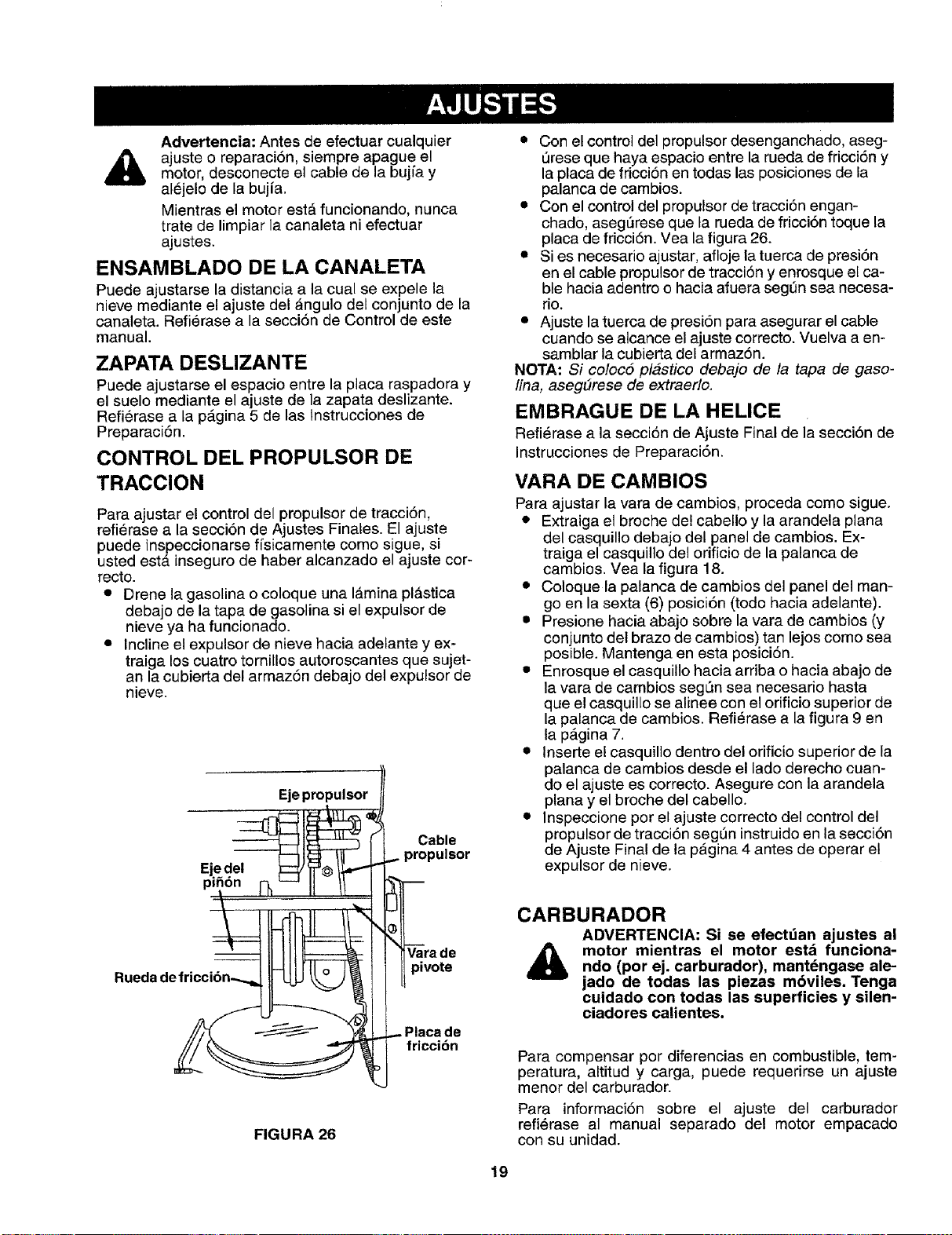
Advertencia: Antes de efectuar cualquier
,_ ajuste o reparaci6n, siempre apague elmotor, desconecte el cable de la bujfa y
al6jelo de la bujfa.
Mientras el motor est& funcionando, nunca
trate de limpiar la canaleta ni efectuar
ajustes.
ENSAMBLADO DE LA CANALETA
Puede ajustarse la distancia a la oual se expele la
nieve mediante el ajuste del _ngulo del conjunto de la
canaleta. Refierase a la secci6n de Control de este
manual.
ZAPATA DESLIZANTE
Puede ajustarse el espacio entre la placa raspadora y
el suelo mediante el ajuste de la zapata deslizante.
Refi6rase a la p_gina 5 de las Instrucciones de
Preparaci6n.
CONTROL DEL PROPULSOR DE
TRACClON
Para ajustar el control del propulsor de tracci6n,
refierase a la secci6n de Ajustes Finales. El ajuste
puede inspeccionarse ffsicamente como sigue, si
usted est,. inseguro de haber alcanzado el ajuste cor-
recto.
• Drene la gasolina o coloque una I_mina plastica
debajo de la tapa de gasolina si el expulsor de
nieve ya ha funcionado.
• Incline el expulsor de nieve hacia adelante y ex-
traiga los cuatro tornillos autoroscantes que sujet-
an la cubierta del armaz6n debajo del expulsor de
nieve.
Eje propulsor
Ejedel
pll
Cable
_ulsor
• Con el control del propulsor desenganchado, aseg-
Qrese que haya espacio entre la rueda de fricci6n y
la placa de fricciSn en todas las posiciones de la
palanca de cambios.
• Con el control del propulsor de tracci6n engan-
chado, aseg_rese que la rueda de fricci6n toque la
placa de fricci6n. Vea la figura 26.
• Si es necesario ajustar, afloje la tuerca de presi6n
en el cable propulsor de tracci6n y enrosque el ca-
ble hacia adentro o hacia afuera segen sea necesa-
rio.
• Ajuste la tuerca de presi6n para asegurar el cable
cuando se alcance el ajuste correcto. Vuelva a en-
samblar la cubierta del armaz6n.
NOTA: Si coloc5 plastico debajo de la tapa de gaso-
lina, asegdrese de extraerlo.
EMBRAGUE DE LA HELICE
Refi_rase a la seccion de Ajuste Final de la secci6n de
Instrucciones de Preparaci6n.
VARA DE CAMBIOS
Para ajustar la vara de cambios, proceda como sigue.
• Extraiga el broche de! cabello y la arandela plana
del casquillo debajo del panel de cambios. Ex-
traiga el casquillo del orificio de la palanca de
cambios. Vea la figura 18.
• Coloque la palanca de cambios del panel del man-
go en la sexta (6) posici6n (todo hacia adelante).
i Presione hacia abajo sobre la vara de cambios (y
conjunto del braze de cambios) tan lejos como sea
posible. Mantenga en esta posici6n.
• Enrosque el casquillo hacia arriba o hacia abajo de
la vara de cambios segL_nsea necesario hasta
que el casquillo se alinee con el orificio superior de
la palanca de cambios. Refierase a la figura 9 en
la p_,gina 7.
• Inserte el casquillo dentro del orificio superior de la
palanca de cambios desde el lado derecho cuan-
do el ajuste es correcto. Asegure con la arandela
plana y el broche del cabello.
• Inspeccione por el ajuste correcto del control del
propulsor de tracci6n segSn instruido en la secci6n
de Ajuste Final de la p&gina 4 antes de operar el
expulsor de nieve.
FIGURA 26
Vara de
pivote
Placa de
friccidn
CARBURADOR
ADVERTENClA: Si se efectdan ajustes al
motor mientras el motor esta funciona-ndo (per ej. carburador), mant_ngase ale-
jade de todas las piezas mbviles. Tenga
cuidado con todas las superficies y silen-
ciadores calientes.
Para compensar por diferencias en combustible, tem-
peratura, altitud y carga, puede requerirse un ajuste
menor del carburador.
Para informaci6n sobre el ajuste del carburador
refi_rase al manual separado del motor empacado
con su unidad.
19
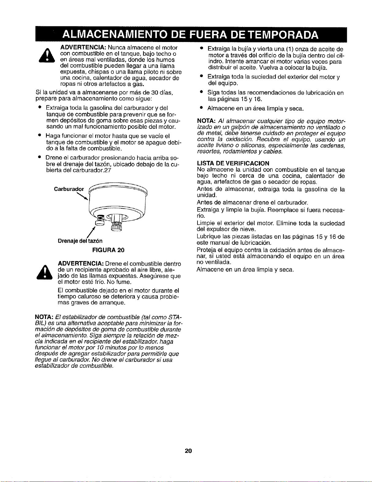
ADVERTENCIA: Nunca almacene el motor
con combustible en el tanque, bajo techo o
en _.reas mal ventiladas, donde los humos
del combustible pueden Ilegar a una llama
expuesta, chispas o una llama pi]oto ni sobre
una cocina, calentador de agua, secador de
ropas ni otros artefactos a gas.
Si la unidad va a almacenarse por m&s de 30 dfas,
prepare para almacenamiento como sigue:
• Extraiga toda la gasolina del carburador y del
tanque de combustible para prevenir que se for-
men dep6sitos de goma sobre esas piezas y cau-
sando un mal funcionamiento posible del motor.
• Haga funcionar el motor hasta que se vacie el
tanque de combustible y el motor se apague debi-
do a la falta de combustible.
• Drene el carburador presionando hacia arriba so-
bre el drenaje del taz6n, ubicado debajo de la cu-
bierta del carburador.27
Drenaje deltazon
FIGURA 20
ADVERTENCIA; Drene el combustible dentro
de un recipiente aprobado al aire libre, ale-
jado de las llamas expuestas. AsegQrese que
el motor este frfo. No fume.
El combustible dejado en el motor durante el
tiempo caluroso se deteriora y causa proble-
mas graves de arranque.
NOTA: El estabilizador de combustible (tat como STA-
BIL) es una alternativa aceptable para minimizar la for-
maciSn de depSsitos de goma de combustible durante
e! almacenamiento. Siga siempre la relaci6n de mez-
cla indicada en el recipiente de/estabitizador, haga
funcionar el motor por 10 minutos por !o menos
despu#s de agregar estabilizador para permitirle que
Ilegue al carburador. No drene el carburador si usa
estabilizador de combustible.
• Extraiga la bujfa y vierta una (1) onza de aceite de
motor a traves del orificio de la bujfa dentro del cil-
indro. Intente arrancar el motor varias veces para
distribuir el aceite. Vuelva a colocar la bujia.
• Extraiga toda la suciedad del exterior del motor y
del equipo.
• Siga todas las recomendaciones de lubricaci6n en
las p_.ginas 15 y 16.
• Almacene en un Area limpia y seca.
NOTA: A! atmacenar cualquier tipo de equipo motor-
izado en un galpSn de almacenamiento no ventilado o
de metal, debe tenerse cuidado en proteger el equipo
contra la oxidaciSn. Recubra el equipo, usando un
aceite liviano o siliconas, especialmente /as cadenas,
resortes, rodamientos y cables.
LISTA DE VERIFICACION
No almacene la unidad con combustible en el tanque
bajo techo ni cerca de una cocina, calentador de
agua, artefactos de gas o secador de ropas.
Antes de almacenar, extraiga toda la gasolina de la
unidad.
Antes de almacenar drene el carburador.
Extraiga y limpie la buj_a. Reemplace si fuera necesa-
rio.
Limpie el exterior del motor. Elimine toda la suciedad
del expulsor de nieve.
Lubrique las piezas listadas en las p_ginas 15 y 16 de
este manual de lubricaci6n.
Proteja el equipo contra la oxidaci6n antes de almace-
nar, si usted est,. almacenando el equipo en un area
no ventilada.
Almacene en un _.rea limpia y seca.
2O
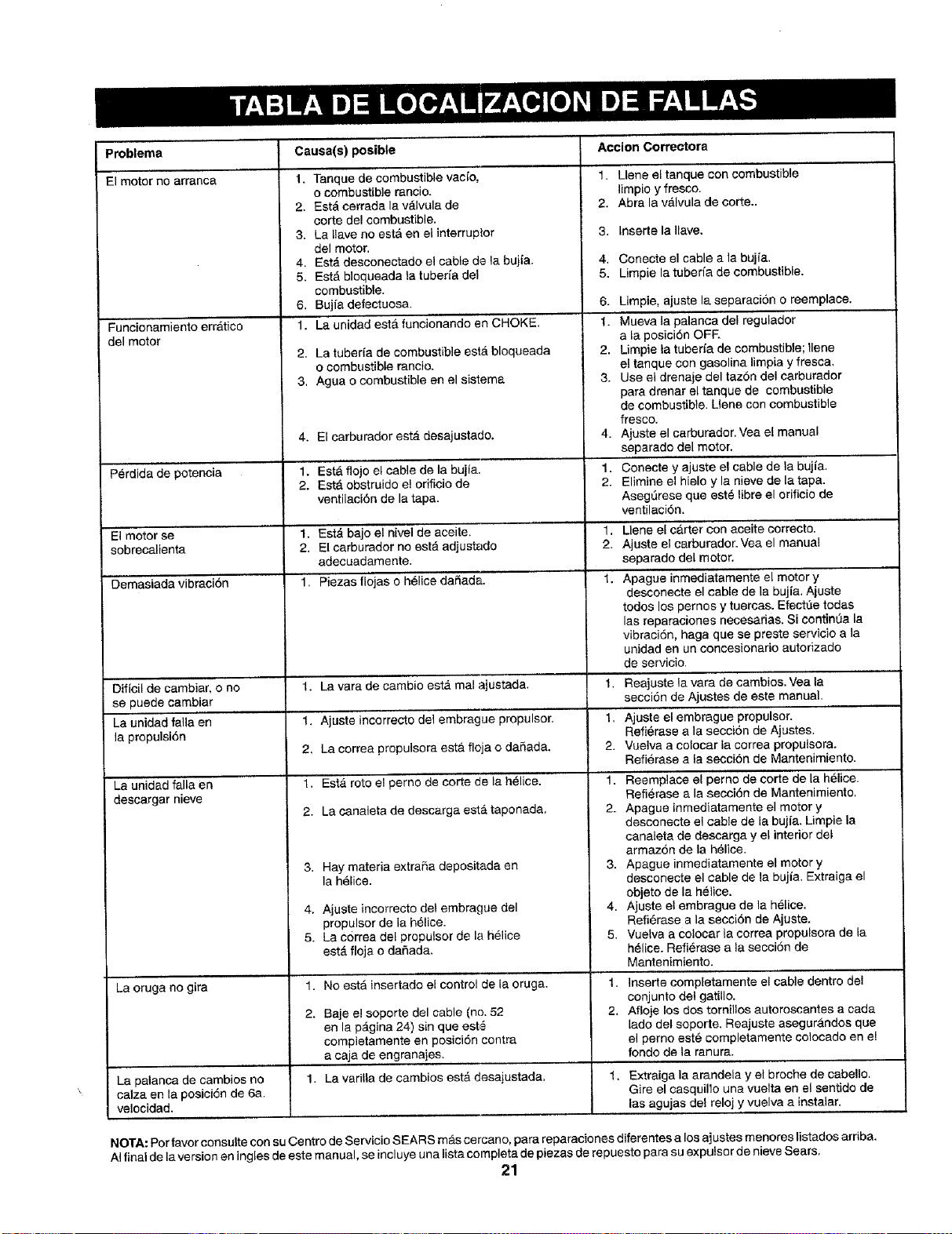
Problerna
El motor no arranca
Funcionamiento err&tico
del motor
Causa(s) posible
1. Tanque de combustible vacio,
o combustible rancio.
2. Est_ cerrade la v_lvula de
corte del combustible.
3. La llave no est& en el interruptor
del motor.
4. Est,. desconectado el cable de la bujia.
5. Est4, bloqueada la tuberia del
combustible.
6. Bujia defectuosa.
1. La unidad est#, funcionando en CHOKE.
2. La tuberia de combustible estb, bloqueada
o combustible rancio.
3. Agua o combustible en el sistema
Accion Correctora
1. Llene el tanque con combustible
limpio y fresco.
2. Abra ta vdlvuta de corte..
3. Inserte lallave.
4. Conecte el cable ala bujia.
5. Limpie la tuberfa de combustible.
6.
1.
2.
3.
4. El carburador est,. desajustado. 4.
Perdida de potencia 1. Est& flojo el cable de la bujia. 1.
2. EstA obstruido e! orificio de 2.
ventilaci6n de la tapa.
El motor se 1. Est_ bajo el nivel de aceite. 1.
sobrecalienta 2. El carburador no est6 adjustado 2.
adecuadamente.
Demasiada vibraci6n 1. Piezas flojas o h61ice da5ada. 1.
LJmpie, ajuste la separaci6n o reemplace,
Mueva la palanca del regulador
ala posici6n OFF,
Limpie la tuberia de combustible; llene
el tanque con gasolina limpia y fresca.
Use el drenaje del taz6n del carburador
pare drenar el tanque de combustible
de combustible. Uene con combustible
fresco.
Ajuste el carburador. Vea et manual
separado del motor.
Conecte y ajuste el cable de la bujia.
Elimine el hielo y la nieve de la tapa.
Aseg_rese que est_ libre el orificio de
ventilaciSn.
1. La vara de cambio est,. mal ajustada.
1. Ajuste incorrecto del embrague propulsor.
2. La correa propulsora est& fleja e daRada.
1. Est,. roto e! perno de eorte de la helice.
2. La canaleta de descarga esta taponada.
Llene el carter con aceite correcto.
Ajuste el carburador. Vea el manual
separado del motor,
Apague inmediatamente e! motor y
desconecte el cable de la bujia. Ajuste
todos los pernos y tuercas. Efect_e todas
las reparaciones necesarias. Si contint_a la
vibraci6n, haga que se preste servicio ala
unidad en un concesionario autorizado
de servicio.
Dificil de cambiar, o no 1. Reajuste la vara de cambios. Vea la
se puede cambiar secci6n de Ajustes de este manual.
La unidad falla en 1. Ajuste el embrague propulsor.
la propulsi6n Refierase a la seccion de Ajustes.
2. Vuelva a colocar la correa propulsora.
Refi_rase ala secci6n de Mantenimiento.
La unidad falla en
descargar nieve
3. Hay materia extrafia depositada en
la h_lice.
4. Ajuste incorrecto del embrague del
propulsor de la h_lice.
5. La correa del proputsor de la helice
est,. floja o da_Sada.
1. NO estA insertado el control de la oruga.
Baje e! soporte del cable (no. 52
en la p4gina 24) sin qua est_
completamente en posici6n contra
a caja de engranajes.
2.
La oruga no gira
1.
2.
3,
4.
5.
Reemplace el perno de corte de la helice.
Refierase ala secci6n de Mantenimiento,
Apague inmediatamente el motor y
desconecte el cable de la bujfa. Limpie la
canaleta de descarga y el interior del
armaz6n de la h_lice.
Apague inmediatamente el motor y
desconecte el cable de la bujia. Extraiga el
objeto de la helice.
Ajuste el embrague de la h_lice.
Refi6rase ala secci6n de Ajuste.
Vuelva a colocar la correa propulsora de la
h#lice. Refierase a la secci6n de
Mantenimiento.
1.
2.
Inserte completamente el cable dentro del
conjunto del gatillo.
Afloje los doe tornillos autoroscantes a cada
lado del soporte. Reajuste asegur4ndoe que
el 13ernoeste completamente colocado en el
fondo de la ranura.
La palanca de cambios no 1. La varilla de cambios est,_ deeajustada. 1. Extraiga la amndela y e_broche de cabello,
calza en la posici6n de 6a. Gire el casquillo una vuelta en el sentido de
velocidad. ,.... las,agujas del reloj y vuelva a instalar,
NOTA: Por favor consulte con su Centro de Servicio SEARS mb,s cercano, para reparaciones diferentes a los ajustes menores listados arriba.
AIfinal de la version en ingles de este manual, se incluye una lista complete de piezas de repuesto pare su expulsa r de nieve Sears.
21

f
Sears se complace en ofrecer a sus clientes
servicio de reparacibn de aparatos electro-
dom_sticos y electrbnicos de todas las marcas.
En Sears, usted puede contar con operadores en
espa_ol, a los que puede Ilamar sin cargo alguno.
Para pedir servicio de reparaci6n
a domicilio,
Llame 24 horas al d(a, 7 dias a la semana
1 800-676-5811
Para ordenar piezas con entrega
a domicilio,
Llame de 7 am a 7 pro, 7 d(as a la semana
1 800-659-7084
SEARS


