perator's nual
I:RRFrSMAN+
Electric Start
SNOW THROWER
Model No. 247.883980
CX
IES
CAUTION" Before using this product,
read this manual and follow all safety
rules and operating instructions.
,, SAFETY
, ASSEMBLY
OPERATION
MAINTENANCE
PARTS LIST
o ESPANOL
Sears Brands Management Corporation, Hoffman Estates, IL 60179, U.S.A.
Visit our website: www.craftsman.com
Form No. 769-08169
(June 15, 2012)
Warranty Statement .................................. Page 2
Safe Operation Practices .......................... Page 3
Safety Labels ............................................ Page 7
Assembly .................................................. Page 8
Operation .................................................. Page 14
Service and Maintenance ......................... Page 19
Off-Season Storage .................................. Page 27
Troubleshooting ........................................ Page 28
Parts List ................................................... Page 29
Repair Protection Agreement ................... Page 48
Espa_ol ..................................................... Page 49
Service Numbers ...................................... Back Cover
CRAFTSMANCXTWOYEAR FULL WARRANTY
FORTWOYEARSfromthe dateof purchase,thisproductis warrantedagainstanydefectsin materialor workmanship.A defective
productwill receivefree repairor replacementif repairis unavailable.
Forwarranty coverage details to obtain free repairor replacement,visitthe web site: www.craftsman.com
Thiswarranty coversONLYdefects in material andworkmanship. Warranty coveragedoes NOTinclude:
• Expendableitemsthatcan wearoutfromnormalusewithinthe warrantyperiod,includingbutnot limitedto augers,augerpaddles,
driftcutters,skidshoes,shaveplate,shearpins,sparkplug,aircleaner,belts,and oil filter.
• Standardmaintenanceservicing,oilchanges,or tune-ups.
Tire replacementor repaircausedby puncturesfrom outsideobjects,such as nails, thorns,stumps,or glass.
• Tireor wheelreplacementor repairresultingfromnormalwear,accident,or improperoperationor maintenance.
• Repairsnecessarybecauseof operatorabuse,includingbut notlimitedto damagecausedbyover-speedingthe engine,or from
impactingobjectsthat bendthe frame,auger shaft,etc.
• Repairsnecessarybecauseof operatornegligence,includingbutnot limitedto,electricaland mechanicaldamagecausedby
improperstorage,failureto usethe propergradeandamountof engineoil,or failureto maintainthe equipmentaccordingto the
instructionscontainedinthe operator'smanual.
• Engine(fuel system)cleaningor repairscausedbyfuel determinedto becontaminatedor oxidized(stale). Ingeneral,fuel shouldbe
usedwithin30 days of its purchasedate.
• Normaldeteriorationandwearof the exteriorfinishes,orproductlabelreplacement.
Thiswarrantyis void if this productisever usedwhileprovidingcommercialservicesor if rentedto anotherperson.
Thiswarrantygivesyou specificlegalrights,andyoumayalsohaveother rightswhichvaryfromstateto state.
Sears Brands ManagementCorporation, Hoffman Estates, IL 60179
EngineOilType: 5W-30
EngineOilCapacity: 37ounces
FuelCapacity: Approx.5 Quarts
SparkPlug: F6RTC(951-10292)
SparkPlugGap: .020"to .030"
Model Number.................................................................
Serial Number .................................................................
Dateof Purchase.............................................................
Recordthe modelnumber,serialnumber
anddateof purchaseabove
© Sears Brands,LLC
2
Thissymbolpointsout importantsafetyinstructionswhich,if not
followed,couldendangerthepersonalsafetyand/orpropertyof
yourselfandothers. Readandfollowall instructionsin this manual
beforeattemptingto operatethismachine.Failureto complywith
theseinstructionsmayresultin personalinjury.Whenyou seethis
symbol,HEEDITSWARNING!
CALIFORNIA PROPOSITION 65
EngineExhaust,someof its constituents,and certainvehicle
componentscontainor emit chemicalsknownto Stateof California
to causecancerandbirthdefectsorotherreproductiveharm,
Thismachinewasbuiltto beoperatedaccordingto the safeopera-
tion practicesinthis manual.As withanytypeof powerequipment,
carelessnessorerroron the partof the operatorcan resultin serious
injury.Thismachineis capableof amputatingfingers,hands,toes
andfeetandthrowingdebris.Failureto observethe followingsafety
instructionscouldresultin seriousinjuryor death.
Your Responsibility--Restrict the useof thispowermachineto
personswho read,understandandfollowthewarningsand instruc-
tionsin this manualand on the machine.
SAVE THESE INSTRUCTIONS!
TRAiNiNG
• Read,understand,andfollowall instructionson the machineand
in themanual(s)beforeattemptingto assembleand operate.
Failureto do socan resultinseriousinjuryto the operatorand/
orbystanders.Keepthismanualin a safeplaceforfutureand
regularreferenceand for orderingreplacementparts.
• Befamiliarwithall controlsand their properoperation.Knowhow
to stopthe machineanddisengagethemquickly.
• Neverallowchildrenunder14yearsof ageto operatethis
machine.Children14andover shouldreadandunderstandthe
instructionsandsafeoperationpracticesin this manualand on
the machineandbe trainedand supervisedby anadult.
Neverallowadultsto operatethis machinewithoutproper
instruction.
• Thrownobjectscan causeseriouspersonalinjury. Planyour
snow-throwingpatternto avoiddischargeof materialtoward
roads,bystandersand the like.
Keepbystanders,petsandchildrenat least75feetfromthe
machinewhile it is in operation.Stopmachineif anyoneenters
the area.
• Exercisecautionto avoidslippingor falling,especiallywhen
operatingin reverse.
PREPARATION
Thoroughlyinspecttheareawherethe equipmentisto beused.
Removeall doormats,newspapers,sleds,boards,wires and other
foreignobjects,whichcouldbe trippedoverorthrownby the auger/
impeller.
• Alwayswear safetyglassesor eyeshieldsduringoperationand
while performingan adjustmentor repairto protectyoureyes.
Thrownobjectswhichricochetcancauseseriousinjuryto the
eyes.
Donot operatewithoutwearingadequatewinteroutergarments.
Donot wearjewelry,longscarvesorotherlooseclothing,which
could becomeentangledin movingparts.Wearfootwearwhich
will improvefootingonslipperysurfaces.
Usea groundedthree-wireextensioncordand receptaclefor all
machineswithelectricstartengines.
Disengageall controlleversbeforestartingthe engine.
Adjustcollectorhousingheightto cleargravelorcrushedrock
surfaces.
• Neverattemptto makeanyadjustmentswhileengineis running,
exceptwherespecificallyrecommendedin the operator'smanual.
Letengineandmachineadjustto outdoortemperaturebefore
startingto clearsnow.
3
Safe Handling of Gasoline
Toavoidpersonalinjuryor propertydamageuseextremecare in
handlinggasoline.Gasolineis extremelyflammableand the vaporsare
explosive.Seriouspersonalinjurycan occurwhengasolineis spilled
onyourselfor yourclotheswhichcan ignite. Washyour skin and
changeclothesimmediately.
• Useonlyan approvedgasolinecontainer.
• Extinguishallcigarettes,cigars,pipesandother sourcesof
ignition.
• Neverfuel machineindoors.
• Neverremovegas capor addfuel whilethe engineis hot or
running.
• Allowengineto coolat leasttwo minutesbeforerefueling.
• Neveroverfill fueltank. Fill tankto nomorethan1/2inchbelow
bottomof filler neckto providespace forfuel expansion.
• Replacegasolinecapandtightensecurely.
• Ifgasolineis spilled,wipe it off theengineandequipment.Move
machineto anotherarea.Wait5 minutesbeforestartingthe
engine.
• Neverstorethe machineorfuel containerinsidewherethereis an
openflame,sparkor pilotlight(e.g.furnace,waterheater,space
heater,clothesdryeretc.).
• Allowmachineto cool at least5 minutesbeforestoring.
• Neverfill containersinsidea vehicleor on a truckor trailerbed
witha plasticliner.Alwaysplacecontainerson the groundaway
fromyour vehiclebeforefilling.
• If possible,removegas-poweredequipmentfrom the truckor
trailerandrefuelit onthe ground.Ifthis is not possible,then refuel
suchequipmenton a trailerwith a portablecontainer,ratherthan
froma gasolinedispensernozzle.
• Keepthe nozzlein contactwith the rimof the fuel tankor
containeropeningat alltimes untilfuelingis complete.Do not use
a nozzlelock-opendevice.
OPERATION
• Do not puthandsorfeetnear rotatingparts,in the auger/impeller
housingor chuteassembly.Contactwith the rotatingpartscan
amputatehandsandfeet.
• Theauger/impellercontrolleveris a safetydevice.Neverbypass
itsoperation.Doingso makesthe machineunsafeandmaycause
personalinjury.
• Thecontrolleversmustoperateeasilyin bothdirectionsand
automaticallyreturnto the disengagedpositionwhenreleased.
• Neveroperatewitha missingor damagedchuteassembly.Keep
all safetydevicesin placeandworking.
• Neverrunanengineindoorsor in a poorlyventilatedarea. Engine
exhaustcontainscarbonmonoxide,an odorlessand deadlygas.
• Do notoperatemachinewhileunder the influenceof alcoholor
drugs.
• Mufflerandenginebecomehotandcan causea burn.Do not
touch.Keepchildrenaway.
• Exerciseextremecautionwhenoperatingon or crossinggravel
surfaces.Stayalertfor hiddenhazardsor traffic.
Exercisecautionwhenchangingdirectionandwhileoperatingon
slopes.Do notoperateon steep slopes.
Planyoursnow-throwingpatternto avoiddischargetowards
windows,walls,carsetc. Thus,avoidingpossibleproperty
damageor personalinjurycausedby a ricochet.
Neverdirectdischargeat children,bystandersand petsor allow
anyoneinfrontof the machine.
Donot overloadmachinecapacityby attemptingto clearsnowat
too fastof a rate.
Neveroperatethis machinewithoutgoodvisibility or light. Always
be sureof yourfootingand keepa firmholdon the handles.Walk,
neverrun.
Disengagepowerto theauger/impellerwhentransportingor not
in use.
Neveroperatemachineat hightransportspeedson slippery
surfaces.Lookdownand behindand usecare whenbackingup.
Ifthe machineshouldstart to vibrateabnormally,stopthe engine,
disconnectthe sparkplugwire andgroundit againstthe engine.
Inspectthoroughlyfor damage.Repairanydamagebefore
startingandoperating.
Disengageall controlleversandstopenginebeforeyouleave
the operatingposition(behindthe handles).Waituntilthe auger/
impellercomesto a completestop beforeuncloggingthechute
assembly,makingany adjustments,or inspections.
Neverput yourhandinthe dischargeor collectoropenings.Do
not unclogchuteassemblywhileengineis running.Shutoff
engineand remainbehindhandlesuntilall movingpartshave
stoppedbeforeunclogging.
Useonly attachmentsandaccessoriesapprovedby the manufac-
turer (e.g.wheelweights,tire chains,cabsetc.). Forinformation
concerningtheseitems,call 1-800-469-4663.
Whenstartingengine,pullcord slowlyuntilresistanceis felt, then
pull rapidly.Rapidretractionof startercord(kickback)will pull
handandarmtowardenginefasterthan youcan let go. Broken
bones,fractures,bruisesor sprainscould result.
Ifsituationsoccur whichare notcoveredinthis manual,use care
andgoodjudgment.
Toorderpartsor scheduleservicefor this product,call 1-800-
469-4663.
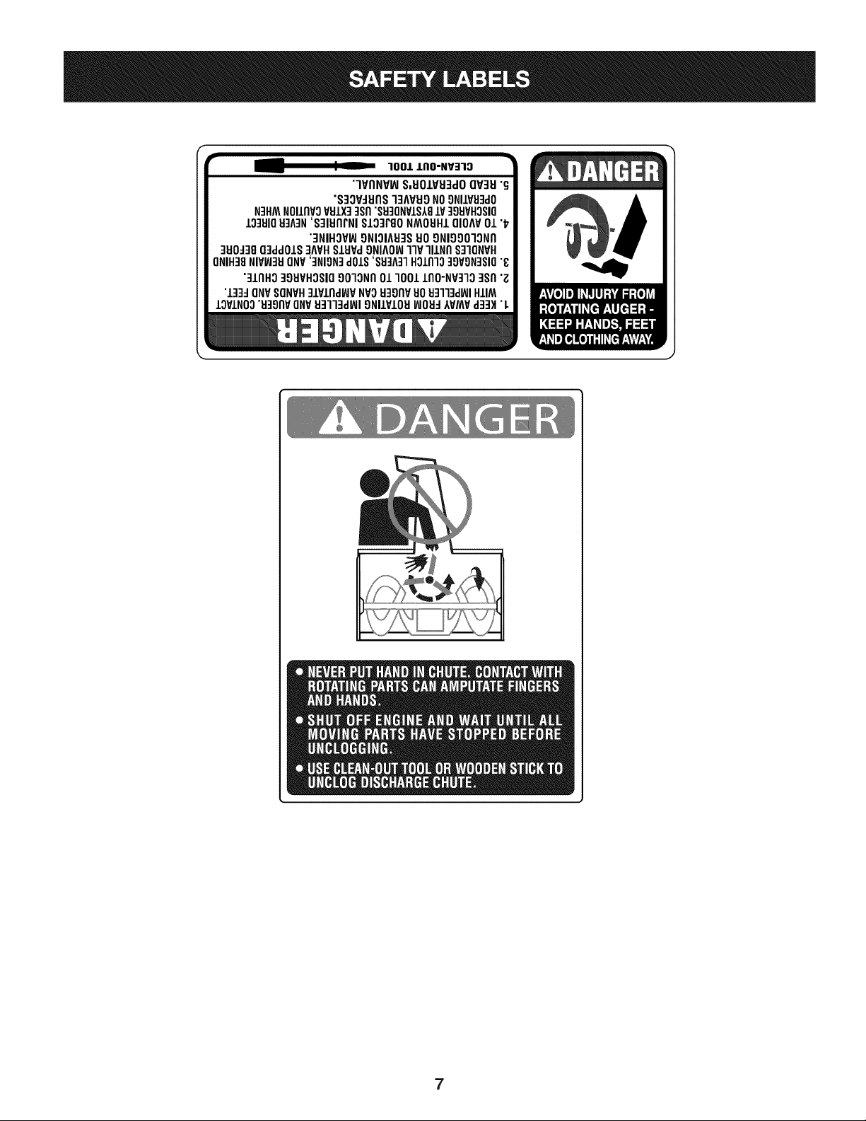
CLEARING A CLOGGED DISCHARGE CHUTE
Handcontactwiththe rotatingimpellerinsidethe dischargechute
is the mostcommoncauseof injuryassociatedwithsnowthrowers.
Neveruse yourhandto cleanout thedischargechute.
Toclear thechute:
1. SHUTTHEENGINEOFF!
2. Wait 10secondsto be surethe impellerbladeshavestopped
rotating.
3. Alwaysusea clean-outtool, not yourhands.
4
MAINTENANCE & STORAGE
• Nevertamperwithsafetydevices.Checktheirproperoperation
regularly.Referto the maintenanceandadjustmentsectionsof
thismanual.
• Beforecleaning,repairing,or inspectingmachinedisengageall
controlleversandstopthe engine.Waituntilthe auger/impeller
cometo a completestop.Disconnectthe sparkplug wireand
groundagainsttheengineto preventunintendedstarting.
Checkboltsand screwsfor propertightnessat frequentintervals
to keepthe machineinsafeworkingcondition.Also,visually
inspectmachinefor anydamage.
Do notchangetheenginegovernorsettingor over-speedthe
engine.Thegovernorcontrolsthe maximumsafeoperatingspeed
of the engine.
Snowthrowershaveplatesand skidshoesaresubjectto wear
anddamage.Foryoursafetyprotection,frequentlycheckall
componentsand replacewithoriginalequipmentmanufacturer's
(OEM)partsonlyas listedinthe Partspagesof thisoperator's
manual.Useof partswhichdonot meetthe originalequipment
specificationsmayleadto improperperformanceandcompro-
misesafety!
Checkcontrolleversperiodicallyto verifytheyengageanddisen-
gageproperlyandadjust,if necessary.Referto the adjustment
sectioninthisoperator'smanualfor instructions.
Maintainor replacesafetyand instructionlabels,as necessary.
Observeproperdisposallawsand regulationsfor gas,oil,etc. to
protectthe environment.
Priorto storing,runmachinea few minutestoclear snowfrom
machineand preventfreezeup of auger/impeller.
Neverstorethe machineorfuel containerinsidewherethereisan
openflame,sparkorpilot lightsuchas a waterheater,furnace,
clothesdryer etc.
Alwaysreferto the operator'smanualfor properinstructionson
off-seasonstorage.
Checkfuelline,tank, cap,andfittingsfrequentlyfor cracksor
leaks.Replaceif necessary.
Do notcrankenginewithsparkplugremoved.
Accordingto the ConsumerProductsSafetyCommission(CPSC)
andthe U.S.EnvironmentalProtectionAgency(EPA),this product
hasan AverageUsefulLifeof seven(7)years,or 60 hoursof
operation.At the endof theAverageUsefulLifehavethe machine
inspectedannuallybyan authorizedservicedealer to ensurethat
allmechanicalandsafetysystemsare workingproperlyand not
wornexcessively.Failureto do so can resultinaccidents,injuries
ordeath.
DO NOT MODIFY ENGINE
Toavoidseriousinjuryor death,do not modifyengineinany way.
Tamperingwiththe governorsettingcanleadto a runawayengineand
causeit to operateat unsafespeeds.Nevertamperwithfactorysetting
of enginegovernor.
NOTICE REGARDING EMiSSiONS
EngineswhicharecertifiedtocomplywithCaliforniaand federal
EPAemissionregulationsfor SORE(SmallOff RoadEquipment)are
certifiedto operateon regularunleadedgasoline,and mayinclude
the followingemissioncontrolsystems:EngineModification(EM),
OxidizingCatalyst(OC),SecondaryAir Injection(SAI)and ThreeWay
Catalyst(TWO)if so equipped.
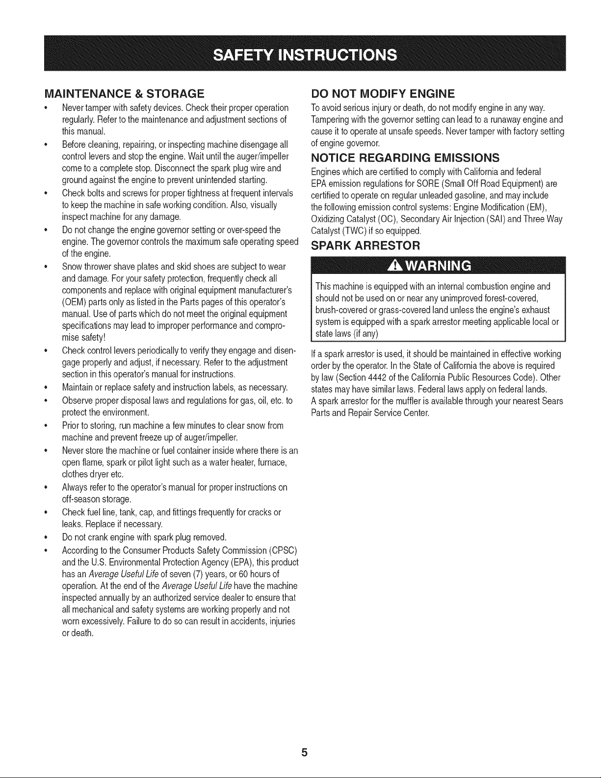
SPARK ARRESTOR
Thismachineisequippedwithaninternalcombustionengineand
shouldnotbe usedonor nearany unimprovedforest-covered,
brush-coveredorgrass-coveredlandunlessthe engine'sexhaust
systemisequippedwitha sparkarrestormeetingapplicablelocalor
statelaws(if any)
Ifa sparkarrestoris used,it shouldbe maintainedin effectiveworking
orderby theoperator.Inthe Stateof Californiathe aboveis required
bylaw (Section4442of the CaliforniaPublicResourcesCode).Other
statesmayhavesimilarlaws. Federallawsapplyonfederallands.
A spark arrestorfor the muffleris availablethroughyournearestSears
PartsandRepairServiceCenter.
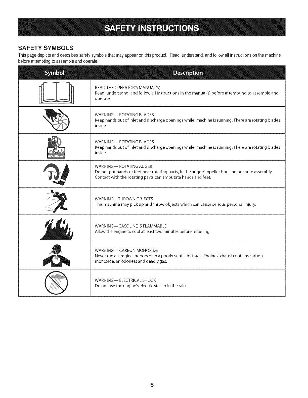
SAFETY SYMBOLS
Thispagedepictsanddescribessafetysymbolsthatmayappearonthisproduct. Read,understand,andfollowall instructionson the machine
beforeattemptingto assembleandoperate.
. +
i
i
"JIp
READ THE OPERATOR'S MANUAL(S)
Read, understand, and follow all instructions in the manual(s) before attempting to assemble and
operate
WARNING-- ROTATING BLADES
Keep hands out of inlet and discharge openings while machine is running. There are rotating blades
inside
WARNING-- ROTATING BLADES
Keep hands out of inlet and discharge openings while machine is running. There are rotating blades
inside
WARNING-- ROTATING AUGER
Do not put hands or feet near rotating parts, in the auger/impeller housing or chute assembly.
Contact with the rotating parts can amputate hands and feet.
WARNING--THROWN OBJECTS
This machine may pick up and throw objects which can cause serious personal injury.
WARNING--GASOLINE IS FLAMMABLE
Allow the engine to cool at least two minutes before refueling.
WARNING-- CARBON MONOXIDE
Never run an engine indoors or in a poorly ventilated area. Engine exhaust contains carbon
monoxide, an odorless and deadly gas+
WARNING-- ELECTRICAL SHOCK
Do not use the engine's electric starter in the rain
6
r
100/.LIIO-NV:IIO
"lVflNV_ S,UOIVU3dOQV3H"G
"S3OV_IJflS]3AVUONO9NIIV_J3dO
N3HMNOIIflVOVSIX] qsfl"S9]ONVIS181V]98VHOSIO
10381083A3N'S]IUflrNI SI03PgoNMOUHIQIOAV01 "_
"3NIHOV_ONIOIA83SUOONIOOO]ONfl
]UO_38O3ddOIS]AVHSlHPd9NIAOW11VlllNfl S]IQNVH
ONIH]8NIVW3UONV']NION]dOlS'88]A]1HOlnlo]9VON]SIO"8
"]lnHg ]gHVHOSIO9010Nfl01 1001 lflO-NP]lO ]Sfl "Z
"l]]d ONVSONVH]lPlnd_P NVOH3onvuoHq]l]d_JIHIIM
IOVINO0"u39npONV_J3113dWI9NllVIOU_JOH_IVMV d]3H "L
7
NOTE:Referencesto rightorleft sideof the snowthrowerare
determinedfromthe operatingpositionlookingforwardto the front of
the machine.
REMOVING FROM CRATE
1. Removescrewsfrom the bottomof thecrate securingthesides,
andendsof the shippingcrate.
2. Lift off the topoff of the crateandsetoutof thewayof the
assemblyarea.
3. Removeand discard plasticbag thatcoversunit.
4. Removeany looseparts includedwith unit (e.g.,Operator's
Manual,etc.).
5. Pushdownonthe lowerhandleandpullunit backout of crate.
6. Makecertainthe crate has beencompletelyemptiedbefore
discardingit.
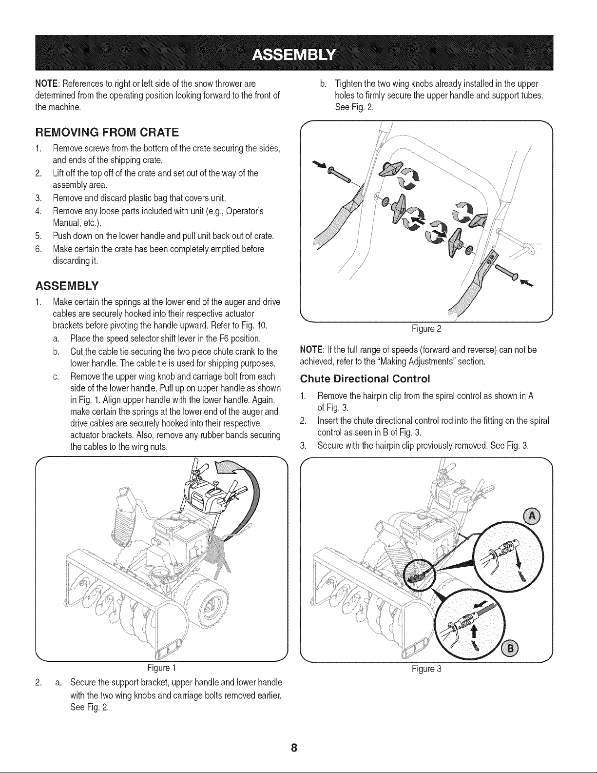
ASSEMBLY
1. Makecertainthe springsat the lowerend of the augeranddrive
cablesaresecurelyhookedintotheir respectiveactuator
bracketsbeforepivotingthe handle upward.Referto Fig. 10.
a. Placethe speedselectorshiftleverin the F6 position.
b. Cut the cabletie securingthe two piecechute crank to the
lowerhandle.Thecable tie is usedfor shippingpurposes.
c. Removethe upperwingknobandcarriageboltfromeach
sideof the lowerhandle.Pulluponupperhandleas shown
in Fig. 1.Align upper handlewith the lowerhandle.Again,
makecertainthe springsat the lowerendof the augerand
drivecablesaresecurelyhookedintotheir respective
actuatorbrackets.Also,removeany rubberbandssecuring
thecablesto thewing nuts.
\
f
Tightenthe twowingknobsalreadyinstalledinthe upper
holesto firmly securethe upperhandleandsupporttubes.
See Fig.2.
!
{
/
/
Figure2
NOTE: Ifthe full rangeof speeds(forwardand reverse)can not be
achieved,referto the "MakingAdjustments"section.
Chute Directional Control
1. Removethe hairpinclip fromthe spiralcontrolas showninA
of Fig.3.
2. Insertthe chutedirectionalcontrolrod into thefitting on the spiral
controlas seenin B of Fig.3.
3. Securewith the hairpinclip previouslyremoved.See Fig.3.
2.
a.
Figure1
Securethe supportbracket,upperhandleand lowerhandle
withthetwo wingknobs andcarriageboltsremovedearlier.
SeeFig.2.
Figure3
8
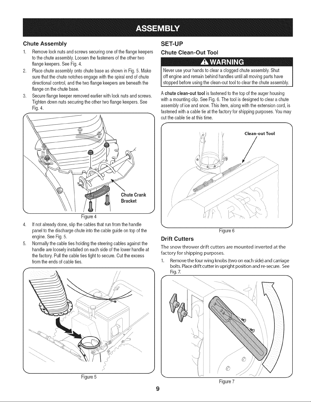
Chute Assembly
1, Removelocknutsandscrewssecuringoneof the flangekeepers
to the chuteassembly,Loosenthefastenersof theothertwo
flangekeepers,SeeFig,4,
2, Placechuteassemblyonto chutebaseas shown in Fig, 5, Make
surethatthe chutenotchesengagewiththe spiralendof chute
directionalcontrol,andthe twoflangekeepersarebeneaththe
flangeonthe chutebase,
3, Secureflangekeeperremovedearlierwithlocknutsandscrews,
Tightendownnutssecuringthe othertwo flangekeepers.See
Fig.4.
.
.
Figure4
If notalreadydone,slipthe cablesthat runfromthe handle
panelto the dischargechuteintothe cableguideontop of the
engine.SeeFig.5.
Normallythecable tiesholdingthe steeringcablesagainstthe
handlearelooselyinstalledoneach sideof the lowerhandleat
the factory.Pullthe cableties tightto secure.Cutthe excess
fromtheendsof cableties.
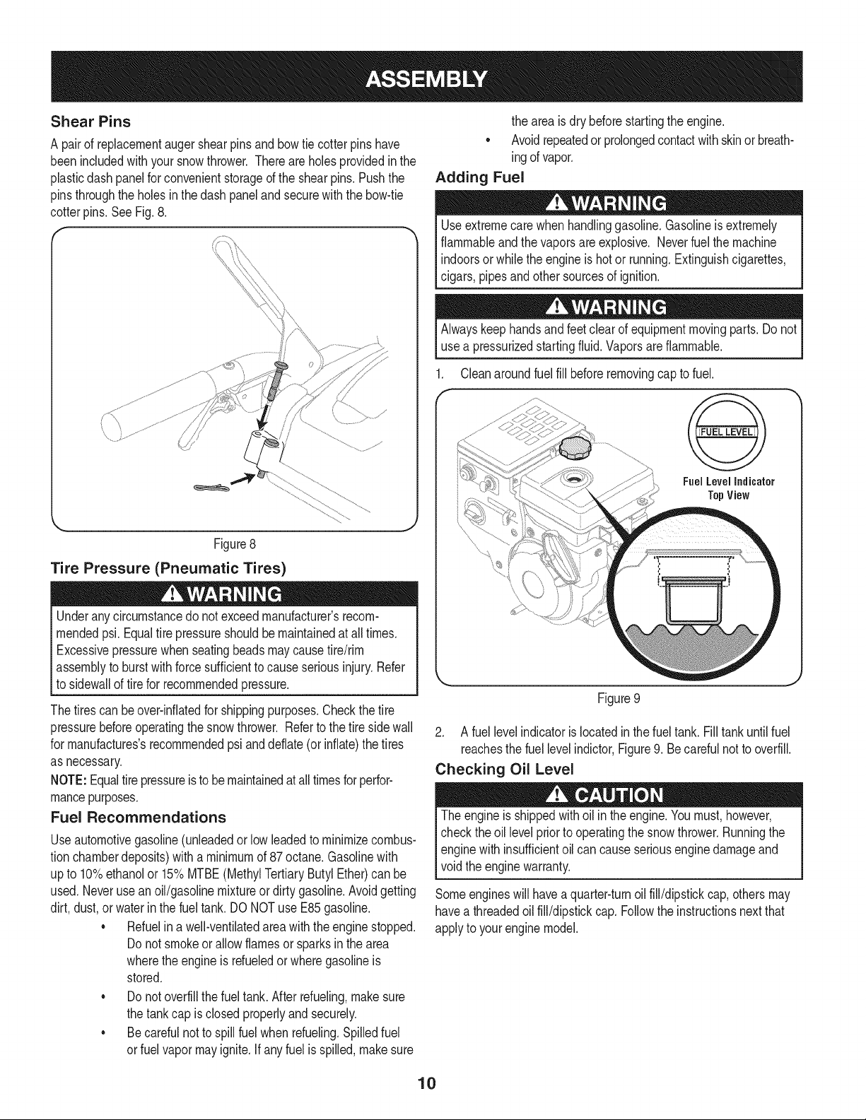
SET-UP
Chute Clean=Out Tool
Neveruseyourhandsto cleara cloggedchuteassembly.Shut
offengineand remainbehindhandlesuntilall movingparts have
stoppedbeforeusingthe clean-outtool to clearthe chuteassembly,
A chuteclean-outtool is fastenedto thetop of the auger housing
witha mountingclip. SeeFig.6. The tool is designedto cleara chute
assemblyof ice andsnow.Thisitem,alongwiththe extensioncord,is
fastenedwitha cabletie at the factoryfor shippingpurposes.Youmay
cut thecable tie at thistime.
Clean=out Tool
\,
(,
//
//
Drift Cutters
Figure6
J
Figure7
J
9
The snow thrower drift cutters are mounted inverted at the
factory for shipping purposes.
1. Removethe four wing knobs (two on each side)and carriage
bolts. Placedrift cutter in upright position and re-secure.See
Fig.7.
ii
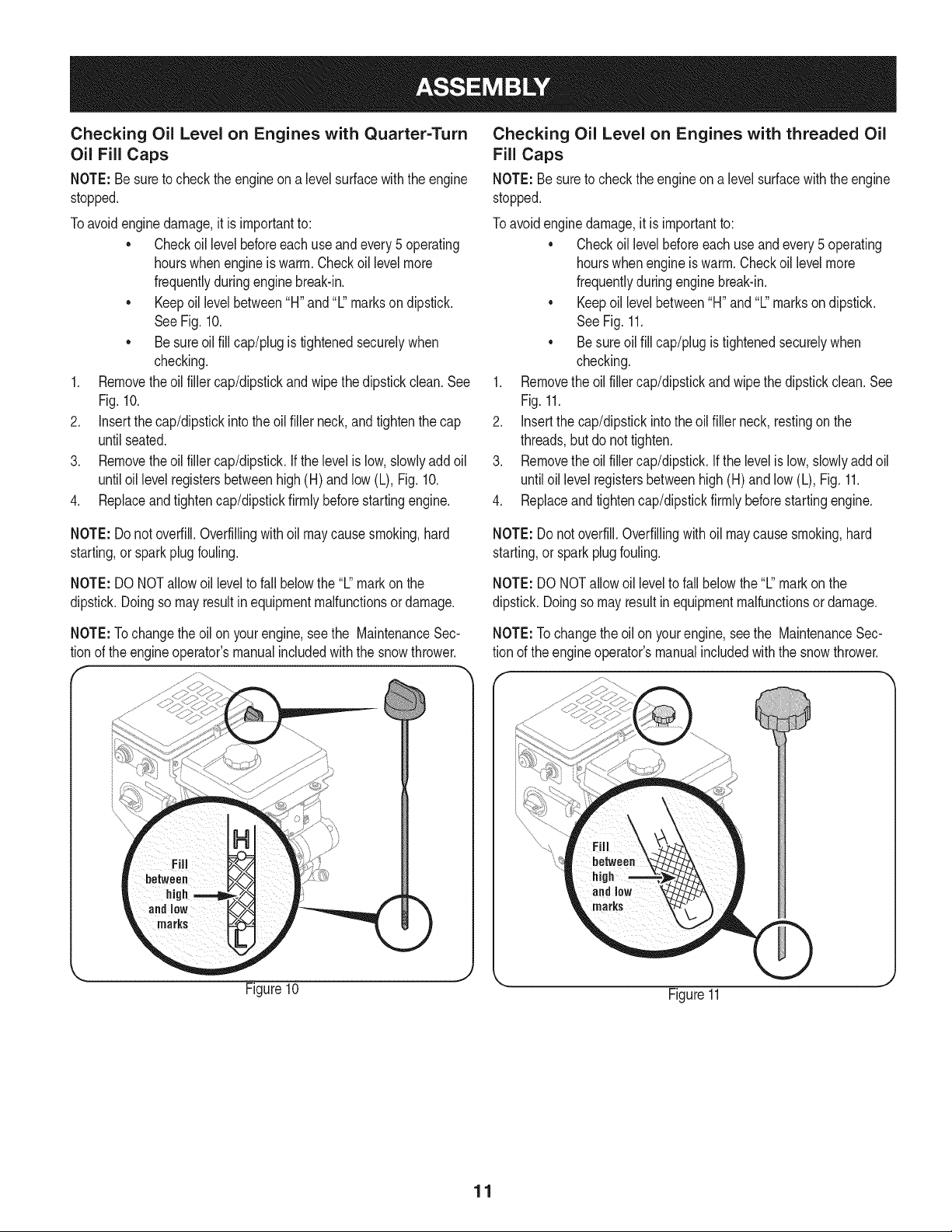
Shear Pins
A pair of replacementaugershearpins and bowtie cotterpins have
beenincludedwithyour snowthrower. Thereareholesprovidedinthe
plasticdash panelfor convenientstorageof the shearpins.Pushthe
pinsthroughthe holesin thedash paneland securewith the bow-tie
cotter pins.See Fig.8.
Figure8
Tire Pressure (Pneumatic Tires)
Underany circumstancedo notexceedmanufacturer'srecom-
mendedpsi.Equaltire pressureshouldbemaintainedat alltimes.
Excessivepressurewhen seatingbeadsmaycausetire/rim
assemblyto burstwithforcesufficientto causeseriousinjury.Refer
to sidewallof tire for recommendedpressure.
The tirescan beover-inflatedfor shippingpurposes.Checkthe tire
pressurebeforeoperatingthe snowthrower. Referto the tire sidewall
for rnanufactures'srecommendedpsianddeflate(or inflate)thetires
as necessary.
NOTE:Equaltirepressureisto be maintainedat alltimesfor perfor-
mancepurposes.
Fuel Recommendations
Useautomotivegasoline(unleadedor low leadedto minimizecombus-
tion chamberdeposits)witha minimumof 87 octane.Gasolinewith
upto 10%ethanolor 15%MTBE(MethylTertiaryButyl Ether)can be
used.Neverusean oil/gasolinemixtureor dirty gasoline.Avoidgetting
dirt, dust,or waterinthe fuel tank.DO NOTuse E85 gasoline.
• Refuelina well-ventilatedareawiththe enginestopped.
Donot smokeor allowflamesor sparksin thearea
wherethe engineis rdueledor wheregasolineis
stored.
• Donot overfillthe fueltank. Afterrefueling,makesure
the tankcap is closed properlyand securely.
• Becarefulnot to spillfuel whenrefueling.Spilledfuel
or fuelvapor mayignite. If any fuelis spilled,makesure
the areais dry beforestartingthe engine.
• Avoidrepeatedor prolongedcontactwith skinor breath-
ingof vapor.
Adding Fuel
Useextremecare whenhandlinggasoline.Gasolineis extremely
flammableandthe vaporsareexplosive.Neverfuel themachine
indoorsorwhile theengineis hotor running.Extinguishcigarettes,
cigars,pipesandother sourcesof ignition.
Alwayskeephandsandfeetclear of equipmentmovingparts.Do not
usea pressurizedstartingfluid. Vaporsare flammable.
Cleanaroundfuel fill beforeremovingcap to fuel.
Fuel Level Indicator
TopView
Figure9
2. A fuel levelindicatoris locatedin the fueltank. Fill tank untilfuel
reachesthe fuel levelindictor,Figure9. Becarefulnot to overfill.
Checking Oil Level
The engineis shippedwithoil in theengine.Youmust,however,
checkthe oil levelpriorto operatingthe snow thrower.Runningthe
enginewith insufficientoil cancauseseriousenginedamageand
void theenginewarranty.
Someengineswill havea quarter-turnoil fill/dipstickcap,others may
havea threadedoil fill/dipstickcap. Followthe instructionsnextthat
applyto your enginemodel.
10
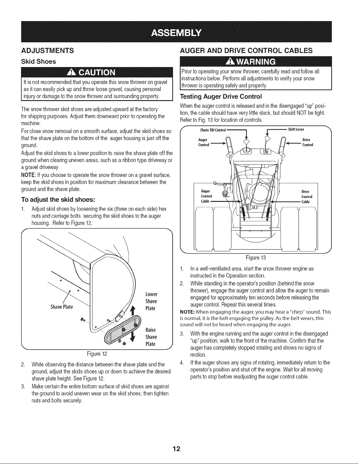
Checking Oil Level on Engines with Quarter=Turn
Oil Fill Caps
NOTE: Besureto checkthe engineona levelsurfacewiththe engine
stopped.
Toavoidenginedamage,it isimportantto:
• Checkoillevelbeforeeachuseandevery5 operating
hourswhenengineiswarm.Checkoil levelmore
frequentlyduringenginebreak-in.
• Keepoil levelbetween"H" and '%'markson dipstick.
SeeFig.10.
• Besureoil fill cap/plug istightenedsecurelywhen
checking.
1. Removetheoil fillercap/dipstickandwipethe dipstickclean.See
Fig.10.
2. Insertthe cap/dipstickintotheoil filler neck,andtightenthecap
untilseated.
3. Removetheoil fillercap/dipstick.If the levelislow,slowlyaddoil
untiloil levelregistersbetweenhigh(H) andlow(L), Fig.10.
4. Replaceandtightencap/dipstickfirmlybeforestartingengine.
Checking Oil Level on Engines with threaded Oil
Fill Caps
NOTE:Be sureto checkthe engineon a levelsurfacewith the engine
stopped.
Toavoidenginedamage,itis importantto:
• Checkoil levelbeforeeach useand every5 operating
hourswhenengine iswarm.Checkoil levelmore
frequentlyduringenginebreak-in.
• Keepoillevelbetween"H" and"L"markson dipstick.
SeeFig.11.
• Besureoil fill cap/plugistightenedsecurelywhen
checking.
1. Removethe oil filler cap/dipstickand wipe thedipstickclean. See
Fig.11.
2. Insertthe cap/dipstickintothe oil filler neck, restingon the
threads,but do nottighten.
3. Removethe oil filler cap/dipstick.If the levelislow,slowlyaddoil
untiloil level registersbetweenhigh (H) andlow (L), Fig.11.
4. Replaceandtightencap/dipstickfirmly beforestartingengine.
NOTE: Donot overfill.Overfillingwithoil maycausesmoking,hard
starting,or sparkplug fouling.
NOTE: DONOTallowoil levelto fall belowthe"L"mark on the
dipstick.Doingso mayresultinequipmentmalfunctionsor damage.
NOTE:Tochangethe oil on yourengine,see the MaintenanceSec-
tionof theengineoperator'smanualincludedwith the snowthrower.
Figure10
NOTE:Do notoverfill.Overfillingwith oil maycausesmoking,hard
starting,or spark plugfouling.
NOTE:DO NOTallowoil levelto fall belowthe "L"markon the
dipstick.Doingso may resultinequipmentmalfunctionsor damage.
NOTE:Tochangethe oil on yourengine,seethe MaintenanceSec-
tion of the engineoperator'smanualincludedwiththe snowthrower.
Figure11
11
ADJUSTMENTS
Skid Shoes
Itis not recommendedthatyou operatethissnowthrowerongravel
as it can easily pick up and throw loosegravel,causingpersonal
injuryor damageto the snowthrowerand surroundingproperty.
The snowthrowerskidshoesareadjustedupwardat thefactory
for shippingpurposes.Adjustthemdownwardpriorto operatingthe
machine.
Forclose snow removalon a smoothsurface,adjustthe skidshoesso
thatthe shaveplateon the bottomof the augerhousingis just offthe
ground.
Adjustthe skidshoesto a lowerpositionto raisethe shaveplateoff the
groundwhenclearingunevenareas, suchas a ribbontypedrivewayor
agraveldriveway
NOTE:If youchooseto operatethe snowthroweron a gravelsurface,
keepthe skidshoesin positionfor maximumclearancebetweenthe
groundandthe shaveplate.
To adjust the skid shoes:
1. Adjustskid shoesby looseningthe six (threeon eachside)hex
nutsandcarriagebolts securingthe skid shoesto the auger
housing. Referto Figure12.
f
ShavePlate
Lower
Shave
Plate
Raise
Shave
Plate
Figure12
J
2. Whileobservingthe distancebetweenthe shaveplateand the
ground,adjustthe skids shoesupor downto achievethe desired
shaveplateheight.See Figure12.
3. Makecertainthe entirebottomsurfaceof skidshoesareagainst
theground to avoidunevenwearon the skidshoes;thentighten
nutsandboltssecurely.
AUGER AND DRIVE CONTROL CABLES
Priorto operatingyour snowthrower,carefullyreadandfollowall
instructionsbelow.Performalladjustmentsto verifyyour snow
throweris operatingsafelyand properly.
Testing Auger Drive Control
Whenthe augercontrolis releasedandinthe disengaged"up" posi-
tion,the cableshouldhavevery little slack, butshouldNOTbetight.
Referto Fig.13for locationof controls.
r c,.,o,,,co.,°,-.--.-] :[------,,,.Levo,
,.ge, & n. D,,vo
H '°°"°'
Auter (_}J__ Drive
Figure13
1. Ina well-ventilatedarea,startthe snowthrowerengineas
instructedinthe Operationsection.
2. Whilestandingin the operator'sposition(behindthe snow
thrower),engagethe augercontrolandallowthe augerto remain
engagedfor approximatelyten secondsbeforereleasingthe
augercontrol.Repeatthis severaltimes.
NOTE: When engaging the auger, you may hear a "chirp" sound. This
is normal, it is the belt engaging the pulley. As the belt wears, this
sound will not be heard when engaging the auger.
3. With the enginerunningand the augercontrolin the disengaged
"up"position,walkto the frontof the machine.Confirmthat the
augerhascompletelystoppedrotatingand showsno signsof
motion.
4. Ifthe augershowsanysignsof rotating,immediatelyreturnto the
operator'spositionandshut off the engine.Waitfor all moving
partsto stopbeforereadjustingthe augercontrolcable.
12
Testing Wheel Drive Control & Speed Selector Lever
Referto Fig.13forlocationofcontrols.
1. Movethespeedselectorshiftleverintosixth(6) position.
2. Withthewheeldrivecontrolreleased,pushthesnowthrowerforward,
thenpullitback.Themachineshouldmovefreely.
3. Engagethedrivecontrolandattemptto movethemachineboth
forwardandback,resistanceshouldbefelt.
4. Movethespeedselectorshiftleverintothefastreverse(R2)position
andrepeattheprevioustwosteps.
Ifyouexperiencedresistancerollingthe unit,eitherwhenrepositioning
thespeedselectorshiftleverfrom6to R2or whenattemptingtomovethe
machinewiththedrivecontrolreleased,adjustthedrivecontrolimmedi-
ately.SeeAdjustingDriveand AugerControls.
Adjusting Wheel Drive & Auger Controls
1. Frombeneaththe handle,pulldownwardon theappropriatecable
andunhookthe springfoundon the end of the cablefrom its
respectiveactuatorbracket.Referto Fig.14.
b_ Rearwardmost holeof
\.. the actuator brackets .1)
Figure14
J
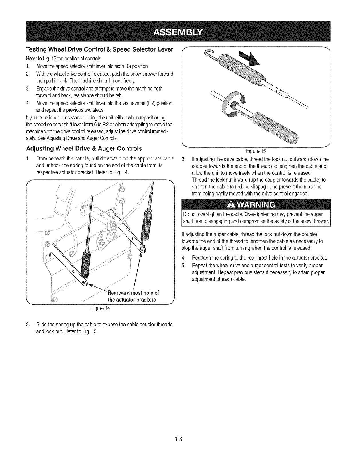
Figure15
Ifadjustingthedrivecable, threadthe lock nutoutward(downthe
couplertowardstheend of thethread)to lengthenthe cableand
allowthe unit to movefreelywhenthe controlis released.
Threadthe locknut inward(upthe couplertowardsthe cable)to
shortenthe cableto reduceslippageandpreventthe machine
frombeingeasilymovedwiththedrive controlengaged.
Do notover-tightenthecable.Over-tighteningmaypreventthe auger
shaftfromdisengagingandcompromisethesafetyofthe snowthrower.
Ifadjustingtheauger cable,threadthe lock nutdownthe coupler
towardsthe endof the threadto lengthenthecable as necessaryto
stopthe augershaftfromturningwhenthe controlis released.
4. Reattachthe springto the rear-mosthole in the actuatorbracket.
5. Repeatthe wheeldriveandaugercontrolteststo verifyproper
adjustment.Repeatpreviousstepsif necessaryto attainproper
adjustmentof eachcable.
2. Slide thespringup thecableto exposethe cablecouplerthreads
andlocknut. Referto Fig. 15.
13
"I- SpeedSelector '_
Lever
Drive ' Chute ControlTM
Headli_
Chute Assembly
Drift Cutters '_
Clean-outTool
Augers
f
SkidShoes
\Auger
Housing
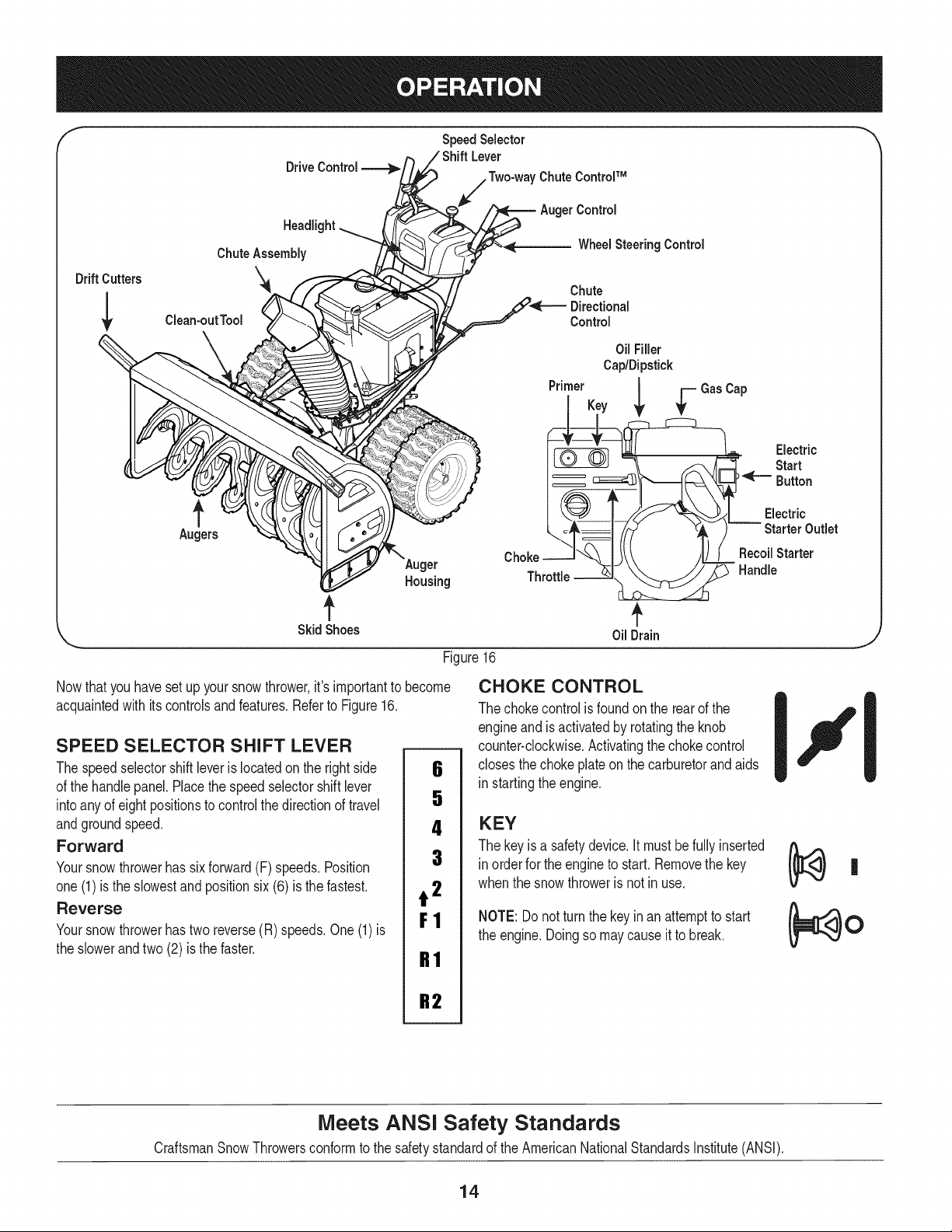
Figure16
Control
Wheel Steering Control
Nowthat youhaveset up yoursnowthrower,it's importantto become
acquaintedwith itscontrolsandfeatures.Referto Figure16.
Chute
Directional
Control
SPEED SELECTOR SHIFT LEVER
The speedselectorshiftleveris locatedon the rightside
of the handlepanel.Placethe speedselectorshiftlever
intoany of eightpositionsto controlthe directionof travel
andgroundspeed.
Forward
Yoursnowthrowerhas sixforward(F) speeds.Position
one(1)is the slowestand positionsix(6) is the fastest.
Reverse
Yoursnowthrowerhastwo reverse(R) speeds.One(1)is
the slowerandtwo (2) is the faster.
6
5
4
3
t 2
F1
R1
R2
Oil Filler
Cap/Dipstick
Primer Key
Throttle
OilDrain
CHOKE CONTROL
The chokecontrolisfoundon the rearof the
engineand is activatedby rotatingthe knob
counter-clockwise.Activatingthechoke control
closesthe chokeplateon thecarburetorandaids
in startingtheengine.
KEY
The keyis a safetydevice.It mustbefullyinserted
in orderfor the engineto start.Removethe key
whenthe snowthroweris notin use.
NOTE: Donot turnthe keyinan attemptto start
the engine.Doingso maycauseit to break.
Electric
Start
Button
Electric
Starter Outlet
RecoilStarter
Handle
J
Meets ANSI Safety Standards
CraftsmanSnowThrowersconformto the safetystandardof the AmericanNationalStandardsInstitute(ANSI).
14
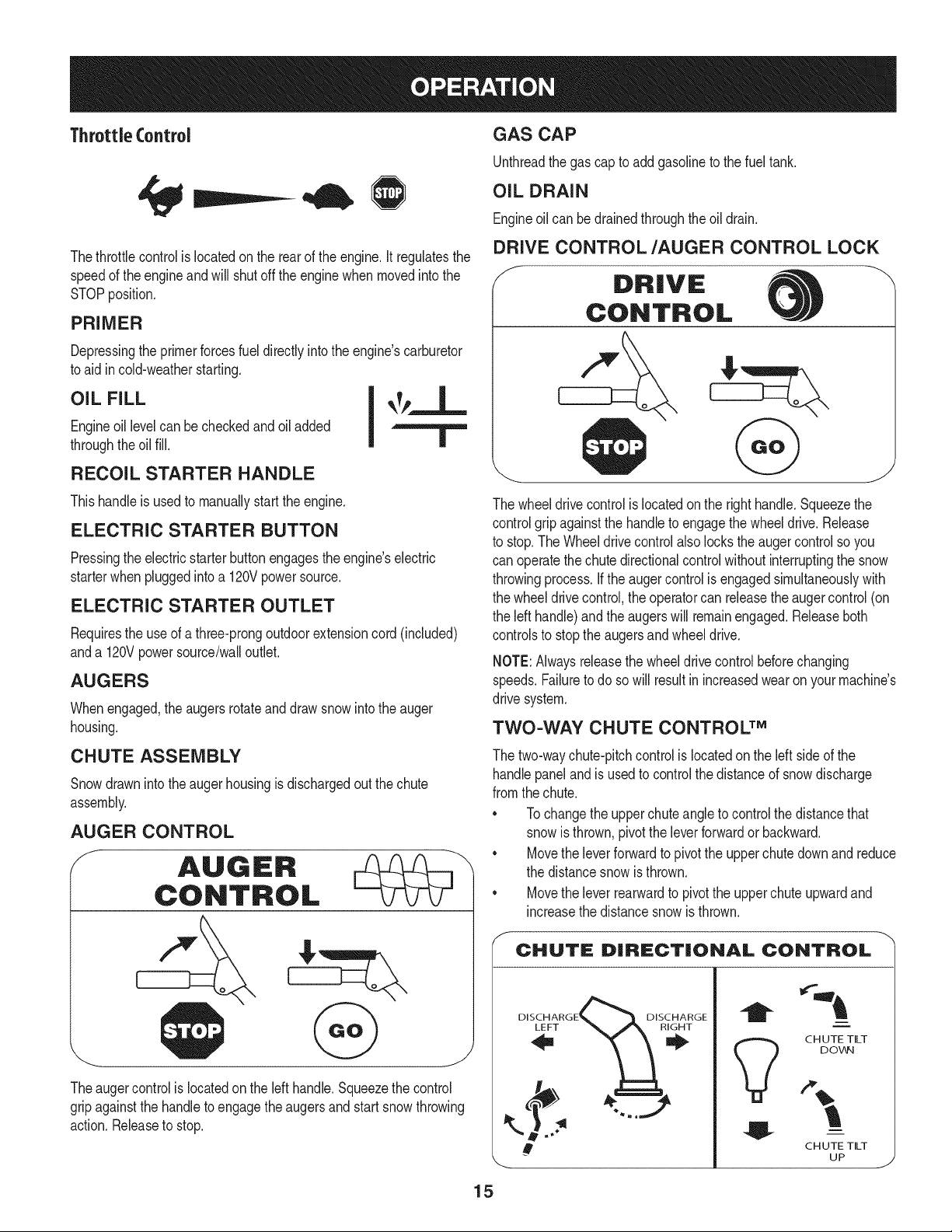
ThrottleControl
Thethrottlecontrolis locatedon the rearof the engine,it regulatesthe
speedof theengine and will shutoff the enginewhenmovedintothe
STOPposition.
PRIMER
Depressingthe primerforcesfuel directlyintothe engine'scarburetor
to aidin cold-weatherstarting.
OIL FILL I _Tp_._-
Engineoil levelcan becheckedand oil added
throughthe oilfill. |
RECOIL STARTER HANDLE
Thishandleis usedto manuallystartthe engine.
ELECTRIC STARTER BUTTON
Pressingthe electricstarterbuttonengagesthe engine'selectric
starterwhenpluggedintoa 120Vpowersource.
ELECTRIC STARTER OUTLET
Requiresthe useof athree-prongoutdoorextensioncord(included)
anda 120Vpowersource/walloutlet.
AUGERS
Whenengaged,the augersrotateand drawsnowintothe auger
housing.
CHUTE ASSEMBLY
Snowdrawninto theauger housingisdischargedout the chute
assembly.
AUGER CONTROL
f
AUGER
CONTROL
Theaugercontrol is locatedonthe left handle.Squeezethecontrol
gripagainstthe handleto engagetheaugersand start snowthrowing
action.Releaseto stop.
GAS CAP
Unthreadthe gas capto addgasolineto the fueltank.
OIL DRAIN
Engineoil can bedrainedthroughthe oildrain.
DRIVE CONTROL/AUGER CONTROL LOCK
f
DRIVE
CONTROL
The wheeldrivecontrolis locatedonthe righthandle.Squeezethe
controlgrip againstthe handleto engagethe wheeldrive. Release
to stop.The Wheeldrivecontrolalsolocks theaugercontrol so you
can operatethe chutedirectionalcontrolwithoutinterruptingthe snow
throwingprocess.Ifthe augercontrolis engagedsimultaneouslywith
the wheeldrivecontrol,the operatorcan releasethe augercontrol(on
the left handle)and theaugerswill remainengaged.Releaseboth
controlsto stopthe augersand wheeldrive.
NOTE:Alwaysreleasethewheeldrivecontrolbeforechanging
speeds.Failureto do sowill result in increasedwearon yourmachine's
drive system.
TWO-WAY CHUTE CONTROL TM
The two-waychute-pitchcontrolis locatedonthe left sideof the
handlepanelandis usedto controlthedistanceof snowdischarge
fromthe chute.
* Tochangethe upperchuteangleto controlthe distancethat
snowis thrown,pivotthe leverforwardor backward.
* Movethe leverforwardto pivotthe upperchutedownand reduce
the distancesnowis thrown.
* Movethe lever rearwardto pivot the upperchute upwardand
increasethe distancesnowis thrown.
CHUTE DiRECTiONAL CONTROL
DISCHARGE_ DISCHARGE
!
CH UTE TILT
DOV_N
CH UTE TILT
UP
J
15
NOTE:To increaseordecreasethe tensiononthe two-waychute
control,tightenor loosenthe wing knobon the chuteassembly.
CHUTE DIRECTIONAL CONTROL
Thechute directionalcontrolis locatedon the left sideof thesnow
thrower.
• Tochangethe directionin whichsnowis thrown,crankclockwiseto
dischargeto the leftand counterclockwiseto dischargeto theright.
SKID SHOES
Positionthe skidshoesbasedon surfaceconditions.Adjust upward
for hard-packedsnow.Adjustdownwardwhenoperatingongravelor
crushedrocksurfaces.
WHEEL STEERING CONTROLS
The leftandrightwheelsteeringcontrolsare locatedon the underside
of the handles.Squeezethe rightcontrolto turn right; squeezethe left
controlto turn left.
NOTE:Operatethe snowthrowerinopenareasuntilyou are familiar
withthesecontrols.
HEADLIGHT
The headlightis locatedinsideof the handlepanel.
DRIFT CUTTERS
Thedrift cuttersaredesignedfor use in deep snow.Theiruse is
optionalfor normalsnowconditions.Maneuverthe snowthrowerso
thatthe cutterspenetratea high standingsnow drift to assist snow
fallingintothe augersfor throwing.
CLEAN-OUT TOOL
Thechute clean-outtool is convenientlyfastenedto the rearof the
augerhousingwitha mountingclip. Shouldsnowandice become
lodgedin thechute assemblyduringoperation,proceedas followsto
safelycleanthechute assemblyandchuteopening:
Neveruseyourhandsto cleara cloggedchuteassembly.Shut
offengineand remainbehindhandlesuntil all movingpartshave
stoppedbeforeunclogging.
1. Releaseboththe AugerControland theWheeldrivecontrol.
2. Stopthe engineby removingthe key.
3. Removethe clean-outtoolfrom the clip whichsecuresit to the
rearof the augerhousing.
4. Usethe shovel-shapedend of theclean-outtoolto dislodgeand
scoopanysnowand icewhichhasformedin andnearthe chute
assembly.
5. Refastentheclean-outtoolto themountingcliponthe rearof the
augerhousing,reinsertthe keyandstartthesnowthrower'sengine.
6. Whilestandingin the operator'sposition(behindthesnow
thrower),engagethe augercontrolfora fewsecondsto clear any
remainingsnowandice fromthechuteassembly.
BEFORE STARTING ENGINE
Read,understand,andfollowall instructionsand warningsonthe
machineandinthis manualbeforeoperating.
Oil
The unitwasshippedwith oil in the engine.Checkoil levelbeforeeach
operationto ensureadequateoil in the engine.Forfurtherinstructions,
referto the Service& Maintenancesectionof this manual.
NOTE: Besureto checkthe engineona levelsurfacewith theengine
stopped.
1. Removethe oil filler cap/dipstickand wipe thedipstickclean.
2. Insertthe cap/dipstickintothe oil fillerneck,and tightenthe cap
turningclockwiseuntilcap is seated.
.
NOTE: Onsomeengines,a threadedscrewcapwill be present
insteadof the quarterturnlockingcap.In the instanceof a
threadedoil cap/dipstick,DO NOTscrewthecap/dipstickinto
check.Checkthe oil by restingthecap/dipstickon the threads,
but not screwingit in.
Removethe oilfiller cap/dipstick.If thelevelis low,slowlyadd
oil (5W-30,witha minimumclassificationof SF/SG)untiloil level
registersbetweenhigh (H) andlow (L).
NOTE: Donot overfill.Overfillingwithoil mayresultinenginesmoking,
hardstartingor sparkplugfouling.
4. Replaceandtightencap/dipstickfirmlybeforestartingengine
Gasoline
Useextremecarewhen handlinggasoline.Gasolineis extremely
flammableandthevaporsare explosive.Neverfuelthe machine
indoorsor whilethe engine is hotor running.Extinguishcigarettes,
cigars,pipesand othersourcesof ignition.
Useautomotivegasoline(unleadedor lowleadedto minimizecombus-
tion chamberdeposits)witha minimumof 87 octane.Gasolinewith
up to 10%ethanolor 15%MTBE(MethylTertiaryButylEther)can be
used.Neverusean oil/gasolinemixtureordirty gasoline.Avoidgetting
dirt, dust,or waterinthe fuel tank.DO NOTuse E85 gasoline.
• Refuelina well-ventilatedareawiththe enginestopped.Do not
smokeor allowflamesor sparksin the areawherethe engineis
refueledor wheregasolineis stored.
• Donot overfillthe fueltank.After refueling,makesurethe tank
cap is closedproperlyandsecurely.
• Becarefulnotto spillfuel whenrefueling.Spilledfuel or fuel vapor
mayignite.Ifany fuelis spilled,makesurethe areais dry before
startingthe engine.
• Avoidrepeatedor prolongedcontactwith skinor breathingof vapor
1. Cleanaroundfuel fill beforeremovingcap to fuel to preventdebris
fromenteringfuel tank..
2. A fuel levelindicatoris locatedin the fueltank. Fill tank untilfuel
reachesthe fuel levelindictor.SeeFigure10inset.Be careful not
to overfill.
16
STARTING THE ENGINE Recoil Starter
Alwayskeephandsand feetclearof movingparts.Do not usea
pressurizedstartingfluid.Vaporsareflammable.
NOTE:Allowtheengineto warm up for a few minutesafter starting.
Theenginewill not developfull poweruntilit reachesoperating
temperatures.
1. Makecertainboththe augercontrolandwheeldrivecontrolare in
the disengaged(released)position.
2. Insertkey intoslot. Makesureit snapsinto place.Do notattempt
to turnthe key.
NOTE:The enginecannotstartwithoutthe key fully insertedintothe
ignitionswitch.
Electric Starter
The optionalelectricstarteris equippedwithagroundedthree-wire
powercord andplug,andis designedto operateon 120volt AC
householdcurrent.It must beusedwith a properlygroundedthree-
prongreceptacleat alltimesto avoidthe possibilityof electric shock.
Followallinstructionscarefullypriorto operatingthe electricstarter.
Determinethatyour home'swiringis a three-wiregroundedsystem.
Aska licensedelectricianif youare not certain.
If youhavea groundedthree-prongreceptacle,proceedas follows:
1. Plugthe extensioncordinto theoutletlocatedonthe engine's
surface.Plugthe otherendof extensioncordinto a three-prong
120-volt,grounded,AC outletin awell-ventilatedarea.
2. Movethrottlecontrolto FAST(rabbit)_ position.
3. Movechoketo the CHOKEpositionI,._1 (coldenginestart).
NOTE: Ifthe engineis alreadywarm,placechokecontrolinthe
RUNpositioninsteadof CHOKEIJl position.
4. Pushprimerthree times(3x), makingsureto covervent hole in
primerbulbwhen pushing.If engineis warm,pushprimeronly
once.Alwayscoverventholewhenpushing.Coolweathermay
requireprimingto be repeated.
5. Pushstarterbuttonto start engine.Oncethe enginestarts,im-
mediatelyreleasestarterbutton.Electricstarteris equippedwith
thermaloverloadprotection;systemwill temporarilyshut-downto
allowstarterto cool if electricstarterbecomesoverloaded.
To prolongstarterlife,useshort startingcycles(5 secondsmaximum
then waitoneminute).
6. As theenginewarms,slowlyrotatethe chokecontrol tothe RUN
position.If the enginefalters,restartengineandrunwithchoke
at half-chokepositionfor a shortperiodof time,and then slowly
rotatethe chokeintothe RUNposition.
7. After engineis running,disconnectpowercordfromelectric
starter.Whendisconnecting,alwaysunplugthe end at the wall
outletbeforeunpluggingtheoppositeendfromthe engine.
Donot pullthe starterhandlewhile theengine running.
1. Movethrottlecontrolto FAST(rabbit)_ position.
2. Movechoketo the CHOKE IJl position'_'(coldengine start). If
engineis warm,placechokeinthe RUNposition.
3. Pushprimerthreetimes,makingsureto coverventholewhen
pushing.If engineis warm,pushprimeronly once.Alwayscover
ventholewhenpushing.Coolweathermay requireprimingto be
repeated.
4. Pullgentlyonthe starterhandleuntilit beginsto resist,thenpull
quicklyandforcefullyto overcomethe compression.Engineshould
start.Donot releasethehandleandallowit to snapback.Return
ropeSLOWLYto originalposition.If required,repeatthis step.
5. As the enginewarms,slowlyrotatethe chokecontrolto the RUN
position.Ifthe enginefalters,restartengineand run with choke
at half-chokepositionfora shortperiodof time,andthenslowly
rotatethechoke intothe RUNposition.
Toavoidunsupervisedengineoperation,neverleavethe machine
unattendedwith the enginerunning.Turnthe engineoff after useand
removekey.
STOPPING THE ENGINE
Afteryou havefinishedsnow-throwing,run enginefor a fewminutes
beforestoppingto helpdry off any moistureon the engine.
1. Movethrottlecontrolto STOPI_ position.
inc. Backfireor en( occur.
2. Removethekey.Removingthekeywillreducethepossibilityof
unauthorizedstartingof theenginewhileequipmentisnotin use.
Keepthekeyin a safeplace.Theenginecannotstartwithoutthekey.
3. Wipeall snowand moisturefromthe areaaroundthe engineas
well as theareain andaroundthe wheeldrivecontrol and auger
control.Also,engageand releasebothcontrolsseveraltimes.
TO ENGAGE WHEEL DRIVE
1. Withthe throttlecontrolinthe Fast(rabbit)_ position,move
speedselector leverintoone of the sixforward(F)positionsor
two reverse(R) positions.Selecta speedappropriatefor the
snowconditionsanda paceyou'recomfortablewith.
NOTE: Whenselectinga DriveSpeed,usethe slowerspeeds
untilyouare comfortableand familiarwith the operationof the
snowthrower.
2. Squeezethe drivecontrolagainstthe handleandthe snow
throwerwill move.Releaseit anddrive motionwill stop.
NOTE:NEVERrepositionthe speedselectorlever(changespeedsor
directionof travel)withoutfirst releasingthe drivecontrolandbringing
the snowthrowerto a completestop.Doingso will resultin premature
wearto the snowthrower'sdrivesystem.
17
TO ENGAGE AUGER
1. Toengagetheaugerandstart throwingsnow,squeezetheauger
controlagainstthe lefthandle.Releaseto stopthe augers.
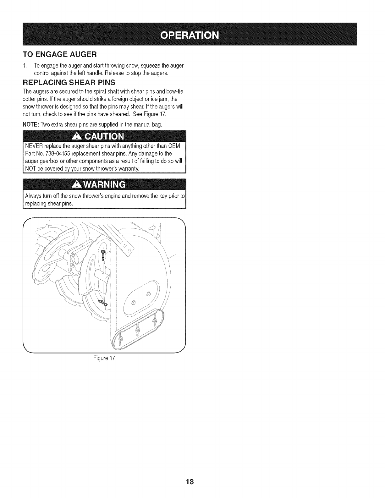
REPLACING SHEAR PINS
Theaugersare securedto the spiralshaftwith shearpinsandbow-tie
cotterpins. If the augershouldstrikea foreignobjector icejam, the
snowthroweris designedso thatthe pins mayshear.If theaugerswill
notturn, checkto seeif the pins havesheared. See Figure17.
NOTE:Twoextra shearpinsare suppliedinthe manualbag.
NEVERreplacetheauger shearpinswith anythingotherthanOEM
Part No.738-04155replacementshearpins. Anydamageto the
I augergearboxor othercomponentsas,a resultof failingto do so will
[ NOTbe coveredby yoursnowthrowers warranty.
Alwaysturnoff the snowthrower'sengineand removethe key prior to
replacingshearpins.
f-
Figure17
18
MAINTENANCE SCHEDULE
Beforeperforminganytypeof maintenance/service,disengageall
controlsand stoptheengine.Waituntilallmovingpartshavecometo a
completestop.Removethekeyto preventunintendedstarting.Always
wearsafetyglassesduringoperationorwhileperforminganyadjustments
orrepairs.
Followthe maintenanceschedulegivenbelow.Thischartdescribes
serviceguidelinesonly. Usethe ServiceLogcolumnto keeptrackof
completedmaintenancetasks.To locate the nearest Sears Service
Centeror to scheduleservice,simplycontactSears at
1-800-4-MY-HOME®.
EachUse
1st5 - 8 hours
25 hours
50 hours
Annuallyor 100 hours
BeforeStorage 1. Fuelsystem
Underheavyload or inhightemperatures
1. Engineoil level
2. Looseor missinghardware
3. Unit and engine.
1. Engineoil
1. Engineoi11-
2. Controllinkagesand pivots
1. Engineoil
1. Sparkplug
= =
1. Check
2. Tightenor replace
3. Clean
1. Change
1. Change
2. Lubewithlightoil
1. Change
1. Cleanand re-gap,orelse replace
withnew plug.
1. Runengineuntilit stopsfromlackof
fuel oradda gasolineadditiveto the
gas in thetank.
ENGINE MAINTENANCE
Checking Engine Oil
Beforelubricating,repairing,or inspecting,disengageallcontrolsand
stopengine.Waituntilall movingpartshavecometo a completestop.
Removethekey to preventunintendedfiringofthe engine.
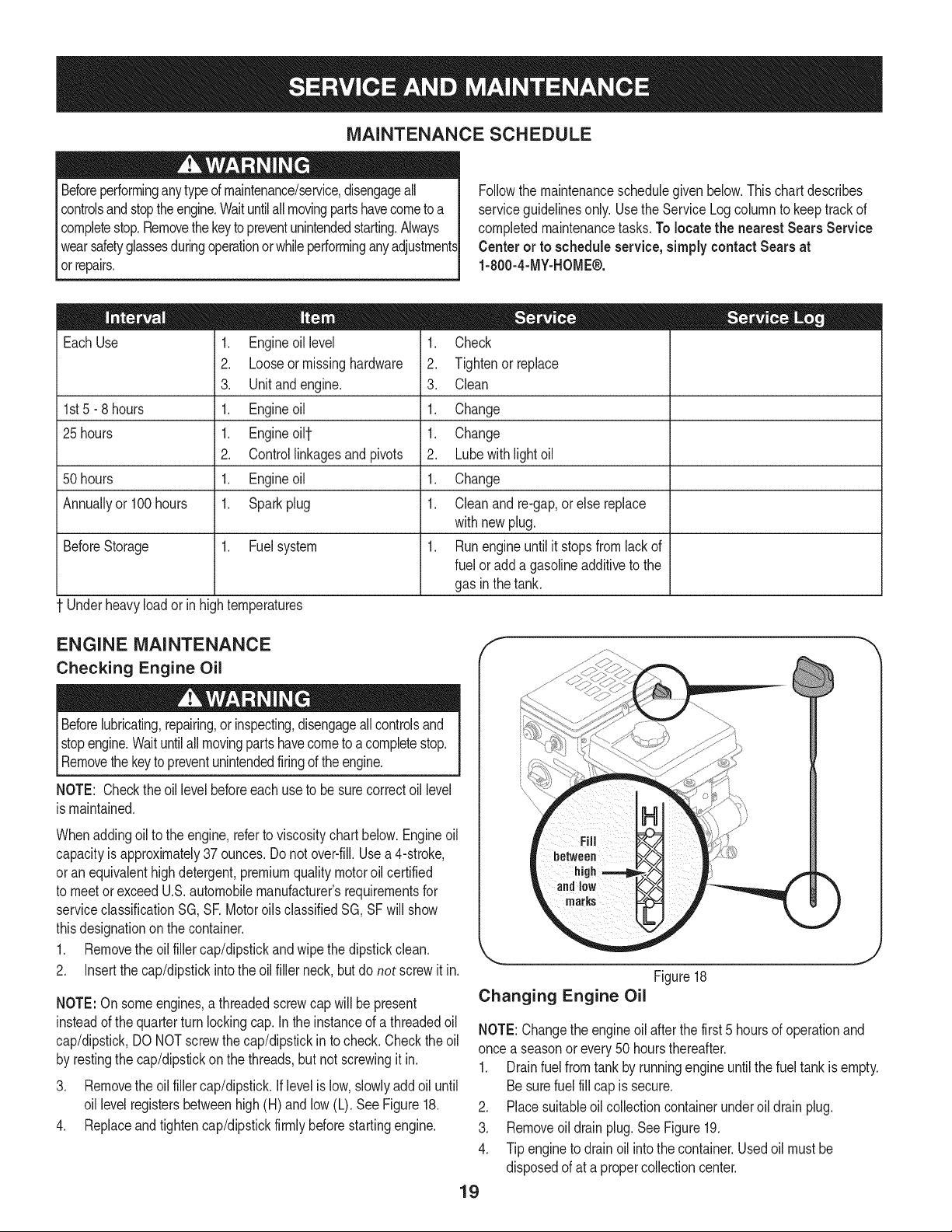
NOTE: Checktheoil levelbeforeeachuseto be surecorrectoil level
is maintained.
Whenaddingoil to the engine,referto viscositychart below.Engineoil
capacityis approximately37 ounces.Donot over-fill.Usea 4-stroke,
oran equivalenthighdetergent,premiumquality motoroil certified
to meetorexceedU.S.automobilemanufacturer'srequirementsfor
serviceclassificationSG, SR MotoroilsclassifiedSG, SFwill show
thisdesignationon the container.
1. Removethe oil fillercap/dipstickandwipethe dipstickclean.
2. Insertthe cap/dipstickintotheoil filler neck,butdo not screwit in.
NOTE:On someengines,a threadedscrewcap will bepresent
insteadof thequarterturn lockingcap.In the instanceof a threadedoil
cap/dipstick,DO NOTscrewthecap/dipstickin to check.Checkthe oil
by restingthe cap/dipstickonthe threads,butnot screwingit in.
3. Removethe oil fillercap/dipstick,if levelis low, slowlyadd oiluntil
oil levelregistersbetweenhigh (H) and low (L). SeeFigure18.
4. Replaceand tighten cap/dipstickfirmlybeforestartingengine.
Figure18
Changing Engine Oil
J
NOTE:Changethe engineoil after thefirst 5 hoursof operationand
once a seasonor every50 hoursthereafter.
1. Drainfuel from tank by runningengine untilthefuel tank is empty.
Besurefuel fill capis secure.
2. Placesuitableoil collectioncontainerunderoil drain plug.
3. Removeoil drainplug.See Figure19.
4. Tip engineto drainoil intothe container.Usedoil mustbe
disposedof at a propercollectioncenter.
19
f
Oil Drain
Plug
Figure19
Usedoil is a hazardouswasteproduct.Disposeof usedoil properly.
Donotdiscardwith householdwaste.Checkwithyourlocalauthori-
tiesor SearsServiceCenterfor safedisposal/recyclingfacilities.
.
6.
Reinstallthe drainplugandtightenit securely.
Refillwiththe recommendedoil andcheckthe oil level.See
RecommendedOil Usage chart. The engine's oil capacity is 37
ounces.
if the enginehas beenrunning,the mufflerwill be very hot. Be careful
not to touchthe muffler.
NOTE: Checkthe sparkplugonce a seasonor every25 hoursof
operation.Changethe sparkplug oncea seasonorevery100hours.
Toensureproperengineoperation,the spark plug mustbe properly
gappedandfree of deposits.
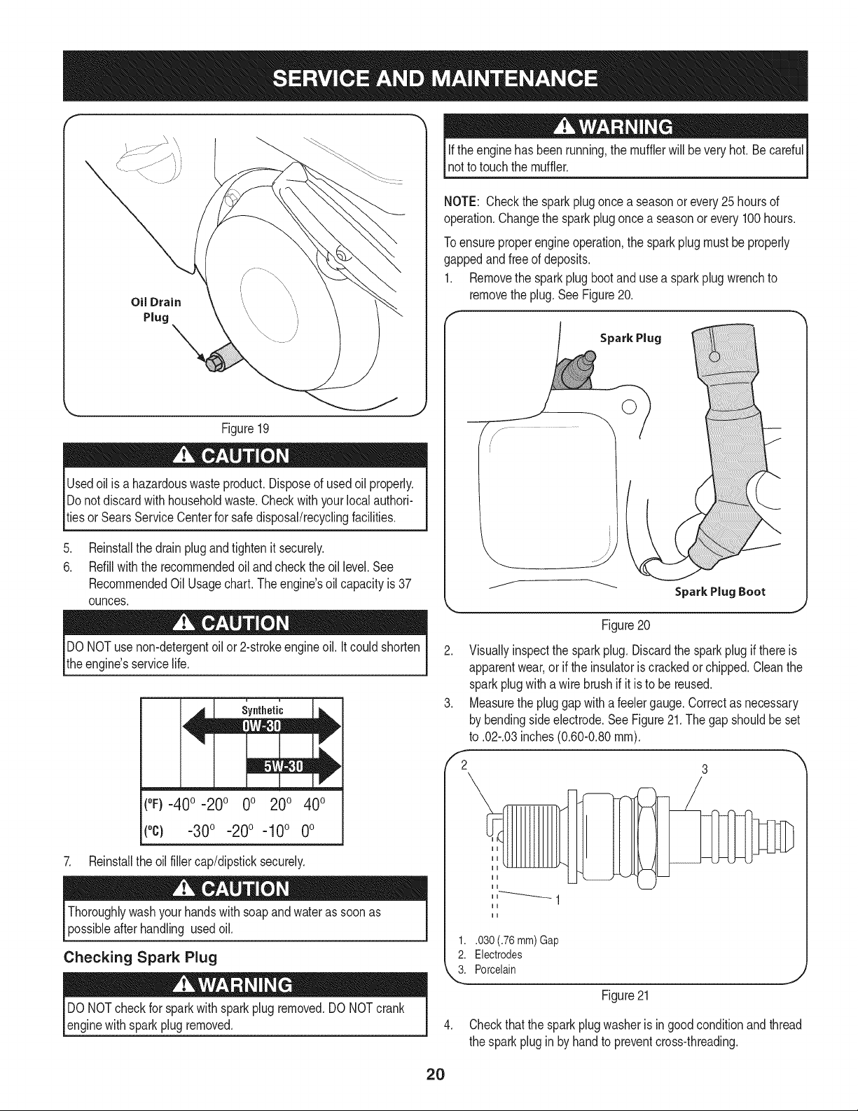
1. Removethe sparkplug bootand usea spark plugwrenchto
removethe plug.SeeFigure20.
Spark Plug
DONOTuse non-detergentoilor 2-strokeengineoil. Itcould shorten
the engine'sservicelife.
(°F}=40o =20o 0o 200 400
(°c) -30° -20° -10 ° 0°
7. Reinstallthe oil fillercap/dipsticksecurely.
Thoroughlywashyour handswithsoapand water as soonas
possibleafterhandling usedoil.
Checking Spark Plug
DO NOTcheckfor sparkwithsparkplugremoved.DO NOTcrank
enginewithsparkplugremoved.
Figure20
2. Visuallyinspectthe sparkplug. Discardthe sparkplug if thereis
apparentwear,or if the insulatoris crackedor chipped.Cleanthe
sparkplugwithawire brushif it is to be reused.
3. Measurethe pluggap with a feelergauge.Correctas necessary
bybendingsideelectrode.See Figure21.Thegap shouldbe set
to .02-.03inches(0.60-0.80ram).
,'2 3
1..030 (.76 mm) Gap
2. Electrodes
k"_i Porcelain
Figure21
4. Checkthatthe sparkplugwasheris ingoodconditionandthread
the sparkpluginby handto preventcross-threading.
2O
5. Afterthe sparkplug is seated,tightenwith a sparkplugwrenchto
compressthe washer.
NOTE:Wheninstallinga newsparkplug,tighten1/2-turnafter the
sparkplugseatsto compressthe washer.Whenreinstallinga used
sparkplug,tighten1/8-to 1/4-turnafter the sparkplugseatsto
compressthe washer.
hot andcan ine.
CARBURETOR ADJUSTMENT
Thecarburetoris notuseradjustable.ContactSearsParts& Repairfor
adjustment.
LUBRICATION
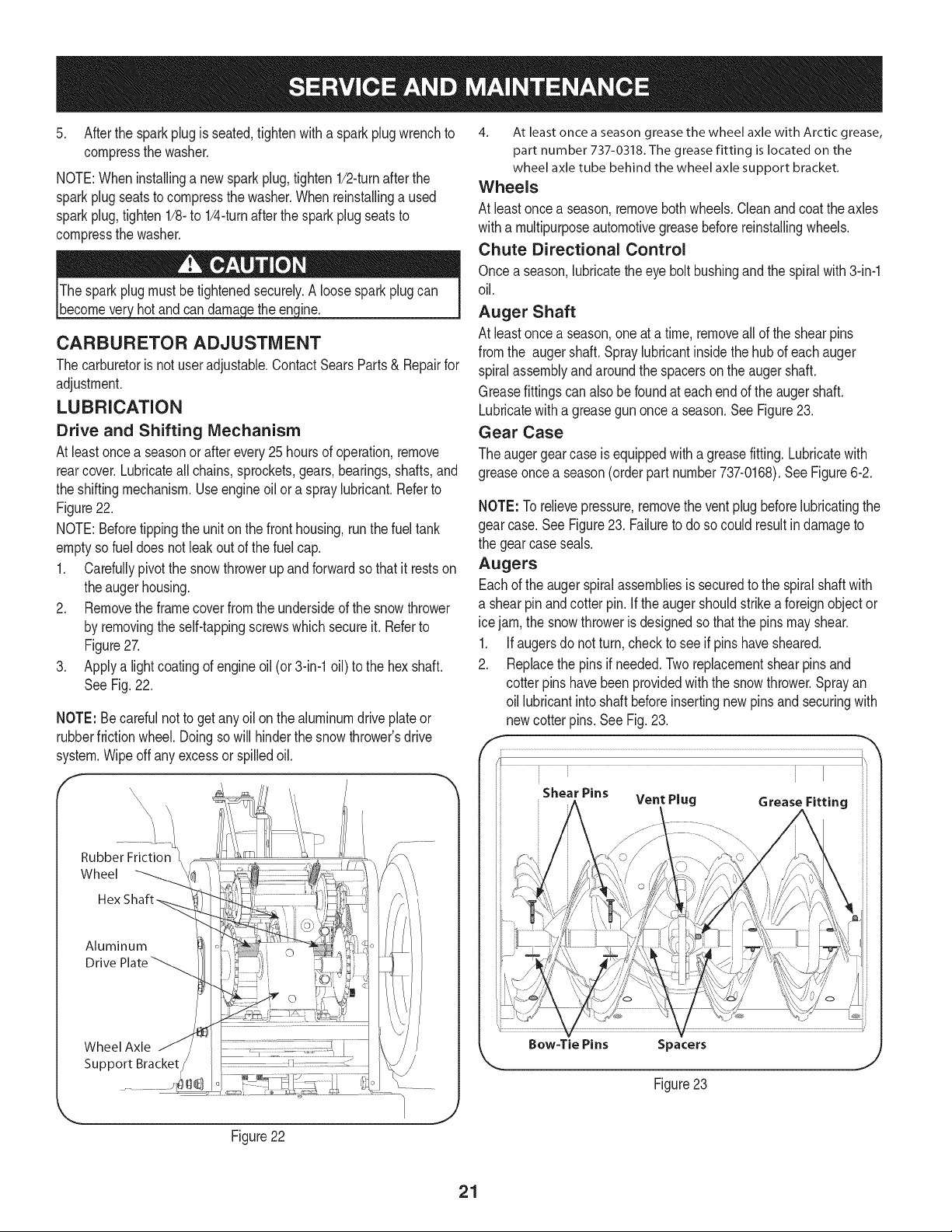
Drive and Shifting Mechanism
At leastoncea seasonor afterevery25 hoursof operation,remove
rearcover.Lubricateall chains,sprockets,gears,bearings,shafts,and
the shiftingmechanism.Useengineoil ora spray lubricant.Referto
Figure22.
NOTE:Beforetippingthe unit onthe fronthousing,runthefuel tank
emptyso fueldoes notleak outof thefuel cap.
1. Carefullypivotthe snowthrowerup and forwardso that it restson
theauger housing.
2. Removethe frame coverfrom the undersideof the snowthrower
by removingthe self-tappingscrewswhichsecureit. Referto
Figure27.
3. Applya lightcoatingof engineoil (or 3-in-1oil) to the hexshaft.
SeeFig.22.
NOTE: Becarefulnotto get any oil on thealuminumdrive plateor
rubberfrictionwheel.Doingso will hinderthe snowthrower'sdrive
system.Wipeoff anyexcessor spilledoil.
/ .............
Aluminum
Drive
Wheel Axle
Support Bracket
4. At least once a season grease the wheel axle with Arctic grease,
part number 737-0318. The grease fitting is located on the
wheel axle tube behind the wheel axle support bracket.
Wheels
At leastoncea season,removebothwheels.Cleanand coat the axles
witha multipurposeautomotivegreasebeforereinstallingwheels.
Chute Directional Control
Once aseason,lubricatethe eyebolt bushingand the spiralwith 3-in-1
oil.
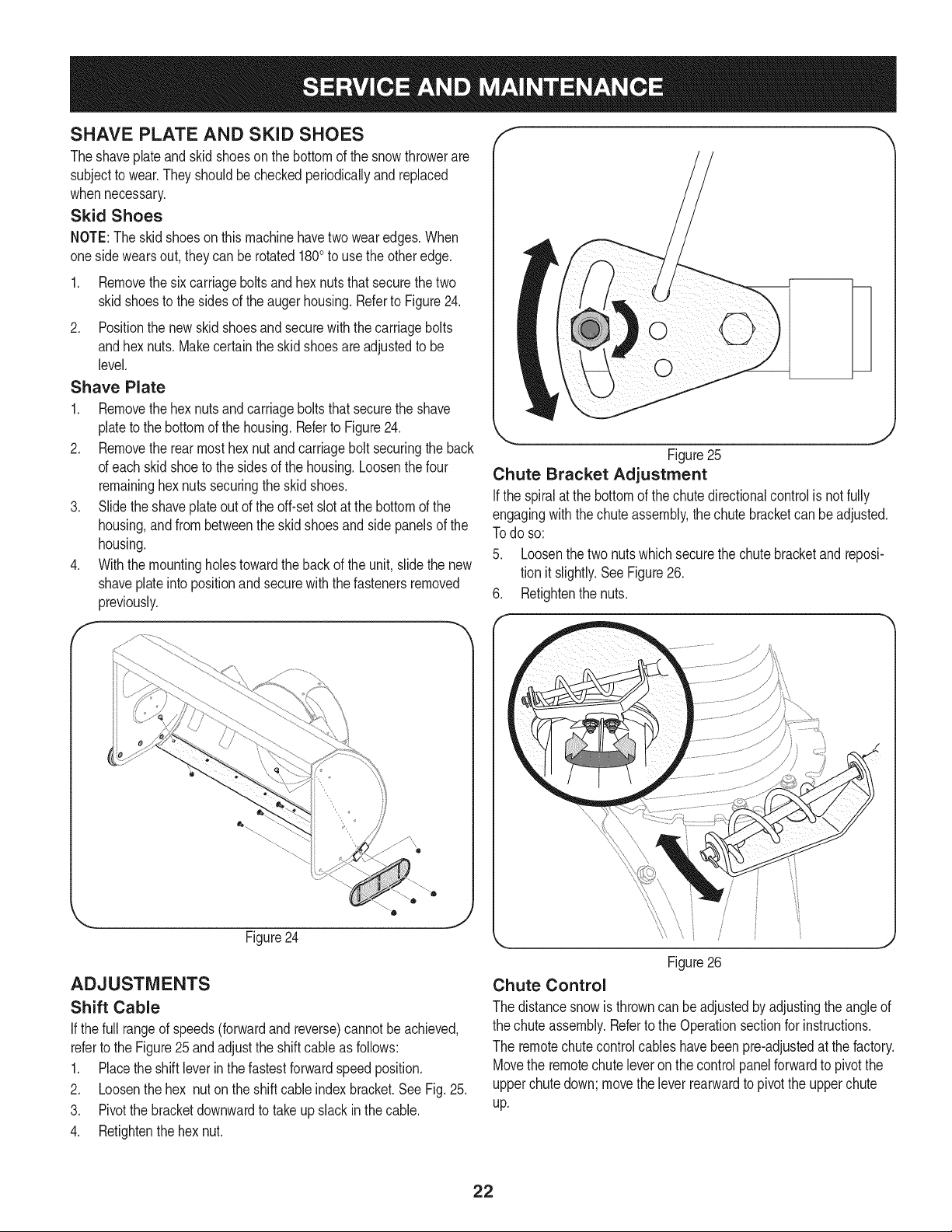
Auger Shaft
At leastoncea season,oneat a time, removeallof theshearpins
fromthe auger shaft.Spraylubricantinsidethe hubof eachauger
spiralassemblyand aroundthe spacerson the augershaft.
Greasefittingscan alsobe foundat each endof the augershaft.
Lubricatewitha greasegun oncea season.See Figure23.
Gear Case
The augergearcaseis equippedwitha greasefitting. Lubricatewith
greaseoncea season(orderpart number737-0168).SeeFigure6-2.
NOTE: Torelievepressure,removethe ventplugbeforelubricatingthe
gearcase.See Figure23. Failureto do so could resultindamageto
the gearcaseseals.
Augers
Eachof the augerspiralassembliesis securedto the spiralshaftwith
a shearpin and cotter pin.If the augershouldstrikeaforeignobjector
ice jam,the snowthroweris designedso that the pinsmay shear.
1. If augersdonot turn, checkto seeif pinshavesheared.
2. Replacethe pinsif needed.Tworeplacementshearpinsand
cotterpins havebeen providedwith the snowthrower.Sprayan
oil lubricantintoshaft beforeinsertingnewpinsand securingwith
newcotter pins.See Fig.23.
i • i I ii
i Shear Pins ii:i
" Vent Plug Grease Fitting
Bow-Tie Pins Spacers
Figure23
Figure22
21
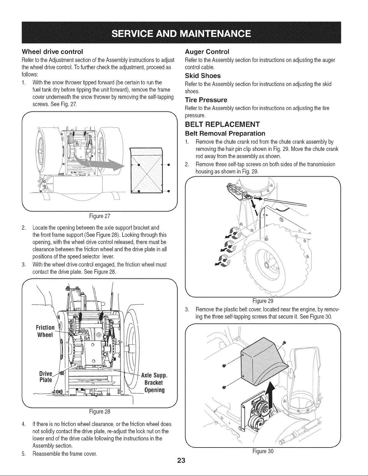
SHAVE PLATE AND SKiD SHOES
Theshaveplateand skidshoesonthe bottomof the snowthrowerare
subjectto wear.Theyshouldbe checkedperiodicallyand replaced
whennecessary.
Skid Shoes
NOTE:Theskid shoes on this machinehavetwo wearedges.When
onesidewearsout, theycan be rotated1800to usethe otheredge.
1. Removethesix carriagebolts and hexnutsthatsecurethe two
skidshoesto the sidesof the augerhousing.Referto Figure24.
2. Positionthe new skidshoesandsecurewiththe carriagebolts
andhex nuts.Makecertainthe skidshoesare adjustedto be
level.
Shave Plate
1. Removethehex nutsandcarriageboltsthatsecurethe shave
plateto the bottomof the housing.Referto Figure24.
2. Removethe rearmost hexnutand carriagebolt securingthe back
of eachskidshoeto the sidesof the housing.Loosenthefour
remaininghexnuts securingthe skidshoes.
3. Slide theshaveplateout of the off-set slotat thebottomof the
housing,and from betweenthe skidshoesandside panelsof the
housing.
4. With the mountingholestowardthe back of the unit,slidethe new
shaveplateinto positionand securewith the fastenersremoved
previously.
f
0
Figure24
ADJUSTMENTS
Shift Cable
If thefull rangeof speeds(forwardand reverse)cannotbe achieved,
referto the Figure25 and adjustthe shiftcable as follows:
1. Placethe shiftleverin thefastestforwardspeedposition.
2. Loosenthe hex nuton the shiftcable indexbracket.See Fig. 25.
3. Pivotthe bracketdownwardto take up slack inthe cable.
4. Retightenthehex nut.
k
J
Figure25
Chute Bracket Adjustment
Ifthe spiralat the bottomof thechutedirectionalcontrolis notfully
engagingwiththechute assembly,the chutebracketcan beadjusted.
Todo so:
5. Loosenthetwo nutswhichsecurethe chutebracketandreposi-
tion it slightly.SeeFigure26.
6. Retightenthenuts.
Figure26
Chute Control
The distancesnowis throwncanbe adjustedbyadjustingthe angle of
the chuteassembly.Referto the Operationsectionfor instructions.
The remotechutecontrolcableshavebeenpre-adjustedat the factory.
Movethe remotechute leveron the controlpanelforwardto pivot the
upperchutedown;movethe leverrearwardto pivotthe upperchute
up.
22
Wheel drive control
Referto the Adjustmentsectionof the Assemblyinstructionsto adjust
thewheeldrive control.Tofurthercheckthe adjustment,proceedas
follows:
1. Withthe snowthrowertippedforward(be certainto runthe
fueltank dry beforetippingthe unitforward),removethe frame
coverunderneaththe snowthrowerby removingthe self-tapping
screws.SeeFig.27.
J
Figure27
2. Locatethe openingbetweenthe axle supportbracketand
thefront frame support(See Figure28). Lookingthroughthis
opening,withthe wheeldrivecontrolreleased,theremustbe
clearancebetweenthefrictionwheelandthe driveplatein all
positionsof the speedselector lever.
3. Withthe wheeldrivecontrolengaged,the frictionwheelmust
contactthedrive plate.SeeFigure28.
Drive -Axle Supp.
Plate Bracket
Opening
Figure28
4. If there isno frictionwheelclearance,or the frictionwheeldoes
not solidlycontactthe driveplate,re-adjustthe locknuton the
lowerend of thedrive cablefollowingthe instructionsin the
Assemblysection.
5. Reassemblethe framecover.
Auger Control
Referto theAssemblysectionfor instructionson adjustingthe auger
controlcable.
Skid Shoes
Referto theAssemblysectionfor instructionson adjustingthe skid
shoes.
Tire Pressure
Referto theAssemblysectionfor instructionson adjustingthe tire
pressure.
BELT REPLACEMENT
Belt Removal Preparation
1. Removethe chutecrank rod from thechute crank assemblyby
removingthe hairpinclip shownin Fig.29. Movethe chutecrank
rodawayfromthe assemblyas shown.
Removethreeself-tapscrewson bothsidesof the transmission
housingas shownin Fig.29.
Figure29
3. Removethe plasticbeltcover,locatednearthe engine,by remov-
ing thethreeself-tappingscrewsthatsecureit.See Figure30.
f
23
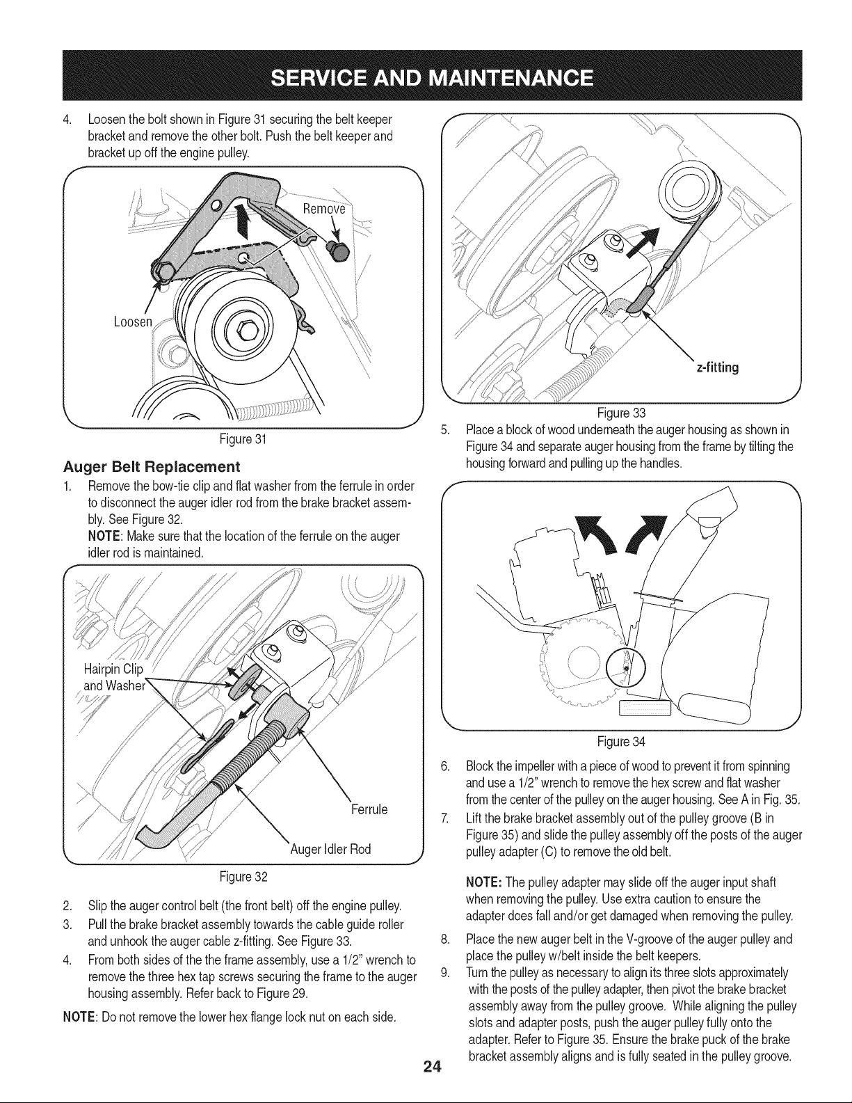
.
Loosenthe bolt shownin Figure31securingthe beltkeeper
bracketandremovetheother bolt.Pushthe belt keeperand
bracketupoff the enginepulley.
Loosen
\
\
Figure31
Auger Belt Replacement
1. Removethebow-tieclip andflatwasherfromtheferrulein order
to disconnectthe augeridlerrodfromthe brakebracketassem-
bly.SeeFigure32.
NOTE:Makesurethat the locationof the ferruleon the auger
idlerrodis maintained.
z-fitting
J
Figure33
Placeablockof woodunderneaththeaugerhousingas shownin
Figure34 andseparateaugerhousingfromtheframeby tiltingthe
housingforwardandpullingup the handles.
HairpinClip
Ferrule
AugerIdler Rod
Figure32
2. Slip the augercontrolbelt (thefront belt) off the enginepulley.
3. Pull the brakebracketassemblytowardsthe cableguide roller
andunhookthe augercable z-fitting.SeeFigure33.
4. Fromboth sidesof the the frameassembly,use a 1/2" wrenchto
removethe threehex tap screwssecuringthe frameto the auger
housingassembly.Referbackto Figure29.
NOTE:Do not removethe lowerhexflangelock nuton eachside.
Figure34
24
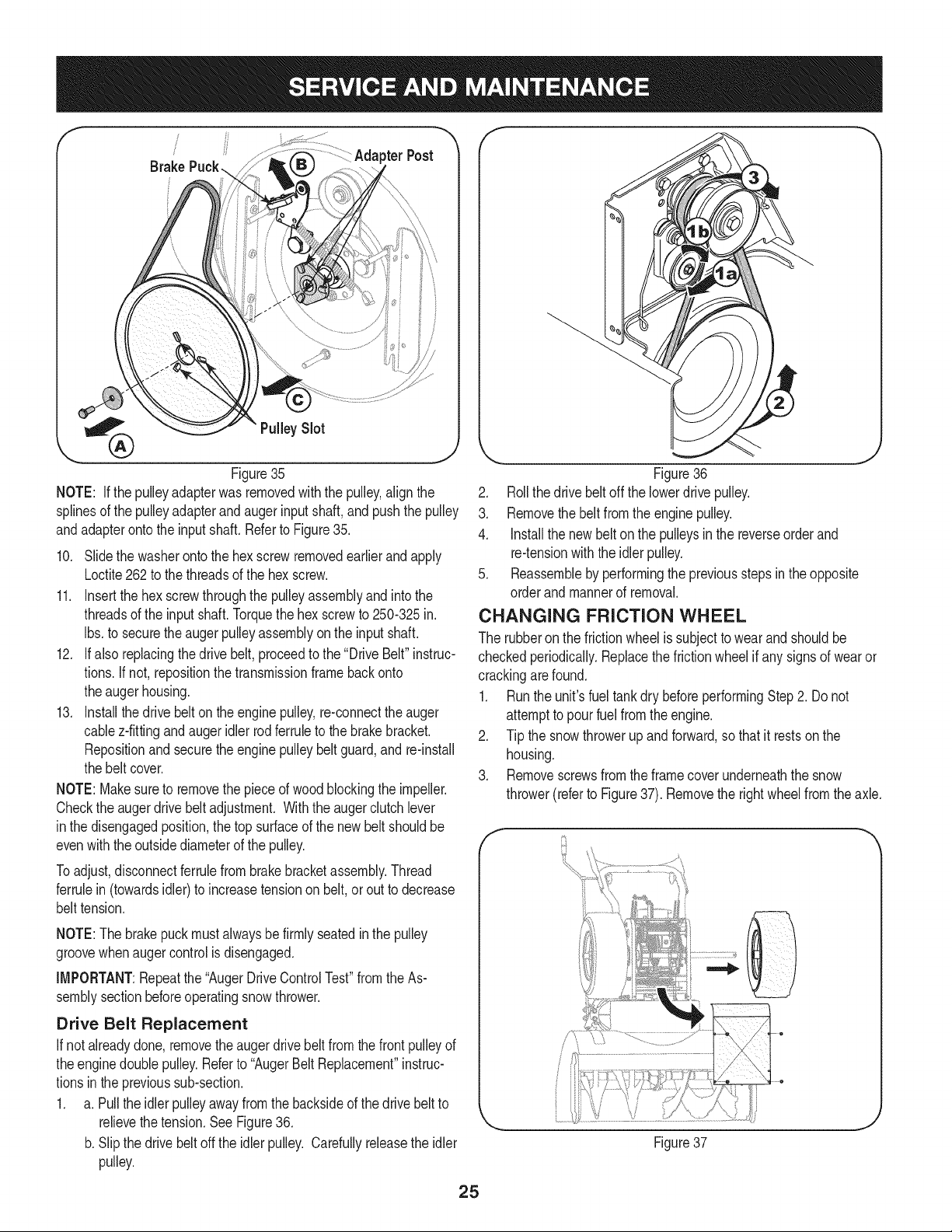
6. Blockthe impellerwith a pieceof woodto preventit fromspinning
andusea 1/2"wrenchto removethe hexscrewand flatwasher
fromthecenterof the pulleyontheaugerhousing.SeeA inFig.35.
7. Lift the brakebracketassemblyout of the pulleygroove(B in
Figure35)andslide the pulleyassemblyoff the postsof the auger
pulleyadapter(C) to removethe old belt.
.
9.
NOTE:Thepulleyadaptermay slideoff the augerinputshaft
when removingthe pulley.Use extracautionto ensurethe
adapterdoesfalland/or get damagedwhen removingthe pulley.
Placethe newaugerbeltin the V-grooveof the augerpulleyand
placethe pulleyw/belt insidethebelt keepers.
Turnthe pulleyas necessaryto alignits threeslotsapproximately
withthepostsof thepulleyadapter,thenpivotthe brakebracket
assemblyawayfromthe pulleygroove. Whilealigningthe pulley
slotsand adapterposts, pushtheaugerpulleyfullyonto the
adapter.Referto Figure35. Ensurethebrakepuck of the brake
bracketassemblyalignsand is fullyseatedin the pulleygroove.
!
pterPost
Brake
%
J
Figure35
NOTE: If the pulleyadapterwas removedwiththe pulley,align the
splinesof the pulleyadapterandaugerinputshaft, and pushthe pulley
andadapterontothe inputshaft. Referto Figure35.
10. Slidethe washerontothe hex screwremovedearlierandapply
Loctite262to thethreadsof the hex screw.
11. Insertthe hexscrewthroughthe pulleyassemblyandintothe
threadsof the inputshaft.Torquethe hex screwto 250-325in.
Ibs.to securethe augerpulleyassemblyon the inputshaft.
12. Ifalso replacingthe drivebelt,proceedto the "DriveBelt"instruc-
tions.If not,repositionthe transmissionframeback onto
theauger housing.
13. Installthedrive belton theenginepulley,re-connectthe auger
cablez-fittingand augeridler rodferruleto the brakebracket.
Repositionand securethe enginepulleybelt guard,and re-install
the beltcover.
NOTE:Makesureto removethe pieceof woodblockingthe impeller.
Checkthe augerdrivebeltadjustment. Withthe augerclutchlever
inthe disengagedposition,thetop surfaceof the newbelt shouldbe
evenwith theoutsidediameterof the pulley.
Toadjust,disconnectferrulefrom brakebracketassembly.Thread
ferrulein (towardsidler) to increasetensionon belt,orout to decrease
belttension.
NOTE:Thebrakepuck mustalwaysbefirmly seatedin the pulley
groovewhenaugercontrol is disengaged.
IMPORTANT:Repeatthe "AugerDriveControlTest"from the As-
semblysectionbeforeoperatingsnow thrower.
Drive Belt Replacement
If notalreadydone,removethe augerdrivebelt from thefrontpulleyof
theengine doublepulley.Referto "AugerBeltReplacement"instruc-
tionsinthe previoussub-section.
1. a. Pull the idlerpulleyawayfrom the backsideof the drivebeltto
relievethetension.See Figure36.
b. Slipthe drivebelt offthe idlerpulley. Carefullyreleasethe idler
pulley.
J
Figure36
2. Rollthe drivebeltoff the lowerdrivepulley.
3. Removethe belt fromthe enginepulley.
4. Installthe newbelton the pulleysinthe reverseorderand
re-tensionwiththe idlerpulley.
5. Reassembleby performingthe previousstepsin theopposite
orderand mannerof removal.
CHANGING FRICTION WHEEL
The rubberonthe frictionwheelis subjectto wearandshouldbe
checkedperiodically.Replacethefrictionwheelif anysignsof wearor
crackingarefound.
1. Runthe unit'sfuel tankdry beforeperformingStep2. Donot
attemptto pourfuel fromthe engine.
2. Tip the snowthrowerupand forward,sothat it restsonthe
housing.
3. Removescrewsfrom theframecoverunderneaththe snow
thrower(referto Figure37). Removethe rightwheelfromthe axle.
e
Figure37
25
.
f
.
.
7.
f
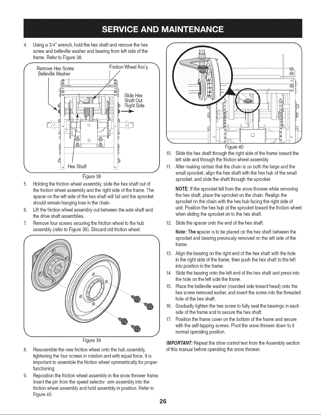
Usinga 3/4" wrench,holdthe hex shaftandremovethe hex
screwand bellevillewasherand bearingfromleft sideof the
frame.Referto Figure38.
RemoveHexScrew
BellevilleWasher
l,
FrictionWheelAss'y.
/
SlideHex
ShaftOut
RightSide
Figure38
Holdingthe frictionwheelassembly,slidethe hex shaftoutof
the frictionwheelassemblyandthe rightsideof theframe.The
spaceronthe left sideof the hex shaftwillfall and the sprocket
shouldremainhanginglosein the chain.
Liftthe frictionwheelassemblyout betweenthe axle shaftand
the driveshaftassemblies.
Removefourscrewssecuringthe frictionwheelto the hub
assembly(referto Figure39). Discardoldfrictionwheel.
!!S i¸i¸i¸;i!!¸i¸:¸¸i¸¸i¸!_¸¸_!¸¸i¸¸¸¸¸¸¸¸¸¸¸¸¸'¸¸¸"i!i_i_!!!i!i;i!iiiiii!iiiii
f
_L
¢-
_,,, J
Figure39
8. Reassemblethe newfrictionwheelontothe hubassembly,
tighteningthe fourscrewsin rotationandwithequalforce.It is
importantto assemblethefrictionwheelsymmetricallyfor proper
functioning.
9. Repositionthe frictionwheelassemblyin the snowthrowerframe.
Insertthe pinfromthe speedselector armassemblyintothe
frictionwheelassemblyand hold assemblyin position.Referto
Figure40.
26
0
Figure40
10. Slidethe hexshaft throughthe rightside of the frametowardthe
Idt sideand throughthe frictionwheelassembly.
11. After makingcertainthat the chainis on boththe largeandthe
smallsprocket,alignthe hex shaftwiththe hexhubof the small
sprocket,andslidethe shaftthroughthe sprocket.
NOTE:If the sprocketfell fromthe snowthrowerwhile removing
the hex shaft,placethe sprocketonthe chain.Realignthe
sprocketonthe chainwiththe hex hubfacingthe rightsideof
unit.Positionthe hexhub of the sprockettowardthe frictionwheel
whenslidingthe sprocketon to the hexshaft.
12. Slidethe spacerontothe endof the hex shaft.
Note: The spaceris to be placedon the hexshaftbetweenthe
sprocketandbearingpreviouslyremovedon the left sideof the
frame.
13. Align the bearingon the rightend of thehex shaftwith the hole
inthe rightside of the frame,then pushthe hexshaftto the left
intopositionin the frame.
14. Slidethe bearingontothe leftendof the hex shaftandpressinto
the holeon theleft sidethe frame.
15. Placethe bellevillewasher(roundedside towardhead)ontothe
hexscrewremovedearlier,and insert thescrewinto thethreaded
holeof the hex shaft.
16. Graduallytightenthe hexscrewto fullyseatthe bearingsineach
sideof the frameandto securethe hex shaft.
17. Positionthe framecoveron the bottomof the frameand secure
withthe self-tappingscrews.Pivotthe snowthrowerdownto it
normaloperatingposition.
iMPORTANT:Repeatthe drivecontroltestfrom the Assemblysection
of this manualbeforeoperatingthe snowthrower.
Ifthesnowthrowerwillnotbeusedfor30daysorlonger,orifitistheendofthesnowseasonwhenthelastpossibilityofsnowisgone,the
equipmentneedstobestoredproperly.Followstorageinstructionsbelowtoensuretopperformancefromthesnowthrowerformanymoreyears.
PREPARING ENGINE
Enginesstoredover30 days need to be drainedof fuel to prevent
deteriorationandgumfromforminginfuel systemor onessential
carburetorparts.If thegasolineinyourenginedeterioratesduring
storage,youmay needto havethe carburetor,and otherfuel system
components,servicedor replaced.
1. Removeall fuel fromtank by runningengineuntil it stops. Donot
attemptto pourfuel fromthe engine.
2. Changethe engineoil.
3. Removesparkplug and pour approximately1 oz. (30 rnl)of clean
engineoil intothe cylinder.Pullthe recoilstarterseveraltimesto
distributetheoil, and reinstallthe spark plug.
4. Cleandebrisfrom aroundengine,andunder,around,andbehind
muffler.Applya lightfilmof oil on anyareasthat are susceptible
to rust.
• Storein a clean,dry andwellventilatedareaawayfromanyap-
pliancethatoperateswithaflameor pilotlight, such as a furnace,
waterheater,or clothesdryer.Avoidany areawith a spark
producingelectricmotor,or wherepowertoolsareoperated.
Neverstoresnowthrowerwith fuel intank indoorsor inpoorlyventi-
latedareas,wherefuel fumesmay reachan openflame,sparkor pilol
lightas ona furnace,water heater,clothesdryer or gas appliance.
• If possible,avoidstorageareaswithhighhumidity.
• Keepthe enginelevelin storage.Tiltingcan causefuel or oil
leakage.
PREPARING SNOW THROWER
Whenstoringthe snowthrowerin an unventilatedor metal stor-
age shed,careshouldbetakento rustprooftheequipment.Using
a light oilor silicone,coat theequipment,especiallyanychains,
springs,bearingsand cables.
• Removealldirt fromexteriorof engineandequipment.
• Followlubricationrecommendations.
• Storeequipmentin a clean,dry area.
• Inflatethe tiresto the maximumPSi. Referto tiresidewall.
27
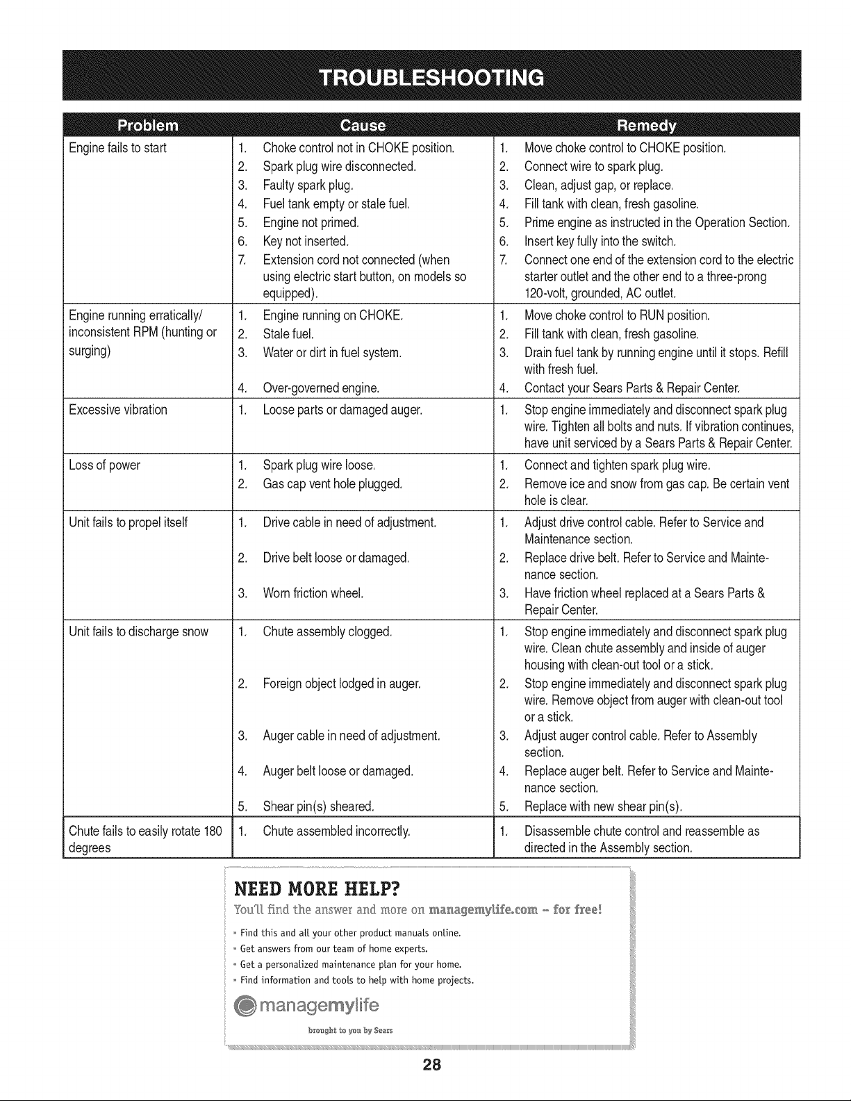
Enginefailsto start
Enginerunningerratically/
inconsistentRPM(huntingor
surging)
Excessivevibration
Lossof power
Unitfailsto propelitself
Unitfailsto dischargesnow
1. Chokecontrolnot in CHOKEposition.
2. Sparkplugwire disconnected.
3. Faultysparkplug.
4. Fueltank emptyor stalefuel.
5. Enginenot primed.
6. Keynot inserted.
7. Extensioncordnot connected(when
usingelectricstartbutton,on modelsso
equipped).
1. Enginerunningon CHOKE.
2. Stalefuel.
3. Wateror dirt in fuel system.
4. Over-governedengine.
1. Loosepartsor damagedauger.
1. Sparkplugwire loose.
2. Gascap vent hole plugged.
1. Drivecable in need of adjustment.
2. Drivebelt looseor damaged.
3. Wornfrictionwheel.
1. Chuteassemblyclogged.
2. Foreignobject lodgedin auger.
3. Augercablein needof adjustment.
4. Augerbelt looseordamaged.
5. Shearpin(s) sheared.
1. Chuteassembledincorrectly.
1. Movechokecontrolto CHOKEposition.
2. Connectwireto sparkplug.
3. Clean,adjustgap,or replace.
4. Filltank with clean,freshgasoline.
5. Primeengineas instructedin the OperationSection.
6. Insertkeyfully intothe switch.
7. Connectone end of the extensioncordto the electric
starteroutletand the otherend to a three-prong
120-volt,grounded,ACoutlet.
1. Movechokecontrolto RUNposition.
2. Filltank with clean,freshgasoline.
3. Drainfueltankby runningengineuntil it stops. Refill
withfreshfuel.
4. ContactyourSearsParts& RepairCenter.
1. Stopengineimmediatelyand disconnectsparkplug
wire.Tightenall boltsand nuts.Ifvibrationcontinues,
haveunit servicedbya SearsParts& RepairCenter.
1. Connectand tightenspark plugwire.
2. Removeiceand snowfromgascap. Be certainvent
holeis clear.
1. Adjustdrivecontrolcable.Referto Serviceand
Maintenancesection.
2. Replacedrive belt. Referto Serviceand Mainte-
nancesection.
3. Havefrictionwheelreplacedat a SearsParts &
RepairCenter.
1. Stopengineimmediatelyand disconnectsparkplug
wire.Cleanchute assemblyand insideof auger
housingwithclean-outtoolor a stick.
2. Stopengineimmediatelyand disconnectsparkplug
wire.Removeobjectfromaugerwith clean-outtool
ora stick.
3. Adjustaugercontrolcable. Referto Assembly
section.
4. Replaceauger belt. Referto Serviceand Mainte-
nancesection.
5. Replacewith newshearpin(s).
Chutefailsto easilyrotate180 1. Disassemblechutecontroland reassembleas
degrees directedinthe Assemblysection.
NEED HORE HELP?
Yot,Fttfind. th_ answer a!"@ mo_e on ma_age_y_ifeocom _ for free]
Find this and att your other product manua[s ontine.
Get answers from our team of home experts.
Get a personalized maintenance p[an for your home.
Find information and tools to he[p with home projects.
28
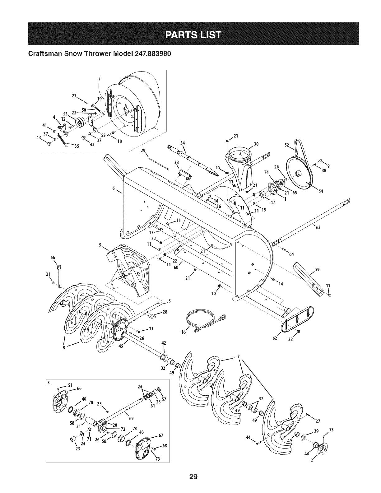
Craftsman Snow Thrower IViodel 247.883980
4
\
o/21
34
30
74
52
47
56
\
10
62 22
/59
11
25
\ 61
583 69
70
\ 24
23
32
44
29
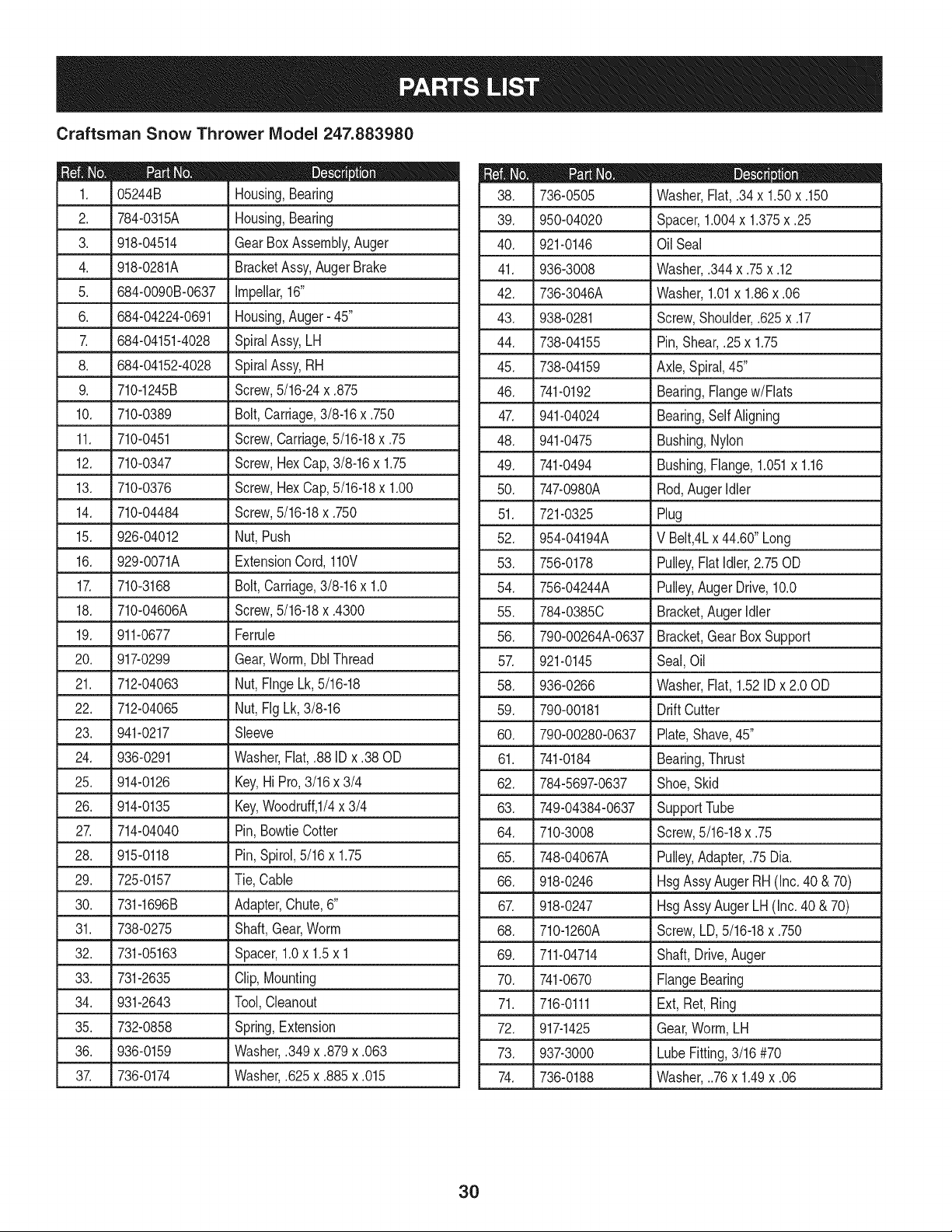
Craftsman Snow Thrower IViodel 247.883980
D = 0 0
05244B Housing,Bearing
2. 784-0315A Housing,Bearing
3. 918-04514 GearBoxAssembly,Auger
4. 918-0281A BracketAssy,AugerBrake
5. 684-0090B-0637 Impellar,16"
6. 684-04224-0691 Housing,Auger- 45"
7. 684-04151-4028 SpiralAssy,LH
8. 684-04152-4028 SpiralAssy,RH
9. 710-1245B Screw,5/16-24x .875
10. 710-0389 Bolt,Carriage,3/8-16x .750
11. 710-0451 Screw,Carriage,5/16-18x .75
12. 710-0347 Screw,HexCap,3/8-16x 1.75
13. 710-0376 Screw,HexCap,5/16-18x 1.00
14. 710-04484 Screw,5/16-18x .750
15. 926-04012 Nut,Push
16. 929-0071A ExtensionCord,110V
17. 710-3168 Bolt,Carriage,3/8-16x 1.0
18. 710-04606A Screw,5/16-18x .4300
19. 911-0677 Ferrule
20. 917-0299 Gear,Worm,DblThread
21. 712-04063 Nut,FlngeLk,5/16-18
22. 712-04065 Nut,Fig Lk, 3/8-16
23. 941-0217 Sleeve
24. 936-0291 Washer,Flat,.88 IDx .38 OD
25. 914-0126 Key,Hi Pro,3/16x 3/4
26. 914-0135 Key,Woodruff,I/4x 3/4
27. 714-04040 Pin,BowtieCotter
28. 915-0118 Pin,Spirol,5/16 x 1.75
29. 725-0157 Tie, Cable
30. 731-1696B Adapter,Chute,6"
31. 738-0275 Shaft,Gear,Worm
32. 731-05163 Spacer,1.0x 1.5x 1
33. 731-2635 Clip,Mounting
34. 931-2643 Tool,Cleanout
35. 732-0858 Spring,Extension
36. 936-0159 Washer,.349x .879x .063
37. 736-0174 Washer,.625x .885x .015
D = O
736-0505 Washer,Flat,.34x 1.50x .150
39. 1950-04020 JSpacer,1.004x 1.375x .25
40. 921-0146 Oil Seal
41. 936-3008 Washer,.344x .75x .12
42. 736-3046A Washer,1.01x 1.86x .06
43. 938-0281 Screw,Shoulder,.625x .17
44. 738-04155 Pin,Shear,.25x 1.75
45. 738-04159 Axle,Spiral,45"
46. 741-0192 Bearing,Flangew/Flats
47. 1941-04024 LBear!ng,Self Aligning
48. 941-0475 Bushing,Nylon
49. 741-0494 Bushing,Flange,1.051x 1.16
50. 747-0980A Rod, AugerIdler
51. 721-0325 Plug
52. 954-04194A V Belt,4Lx 44.60"Long
53. 756-0178 Pulley,Flat idler,2.75 OD
54. 756-04244A Pulley,AugerDrive,10.0
55. 1784-0385C JBracket.Auger Idler
56. 790-00264A-0637 Bracket,GearBox Support
57. 921-0145 Seal,Oil
58. 936-0266 Washer,Flat,1.52IDx 2.00D
59. 790-00181 Drift Cutter
60. 790-00280-0637 Plate,Shave,45"
61. 741-0184 Bearing,Thrust
62. 784-5697-0637 Shoe,Skid
63. 1 749-04384-0637 _SupportTube
64. 710-3008 Screw,5/16-18x .75
65. 748-04067A Pulley,Adapter,.75Dia.
66. L918-0246 LHsgAssyAuger RH (Inc.40 &70)
67. 918-0247 HsgAssyAuger LH(Inc. 40 & 70)
68. 710-1260A Screw,LD,5/16-18x .750
69. 711-04714 Shaft,Drive,Auger
70. 741-0670 FlangeBearing
71. 716-0111 Ext, Ret,Ring
72. 917-1425 Gear,Worm,LH
73. 937-3000 LubeFitting,3/16#70
74. 736-0188 Washer,..76x 1.49x .06
3O
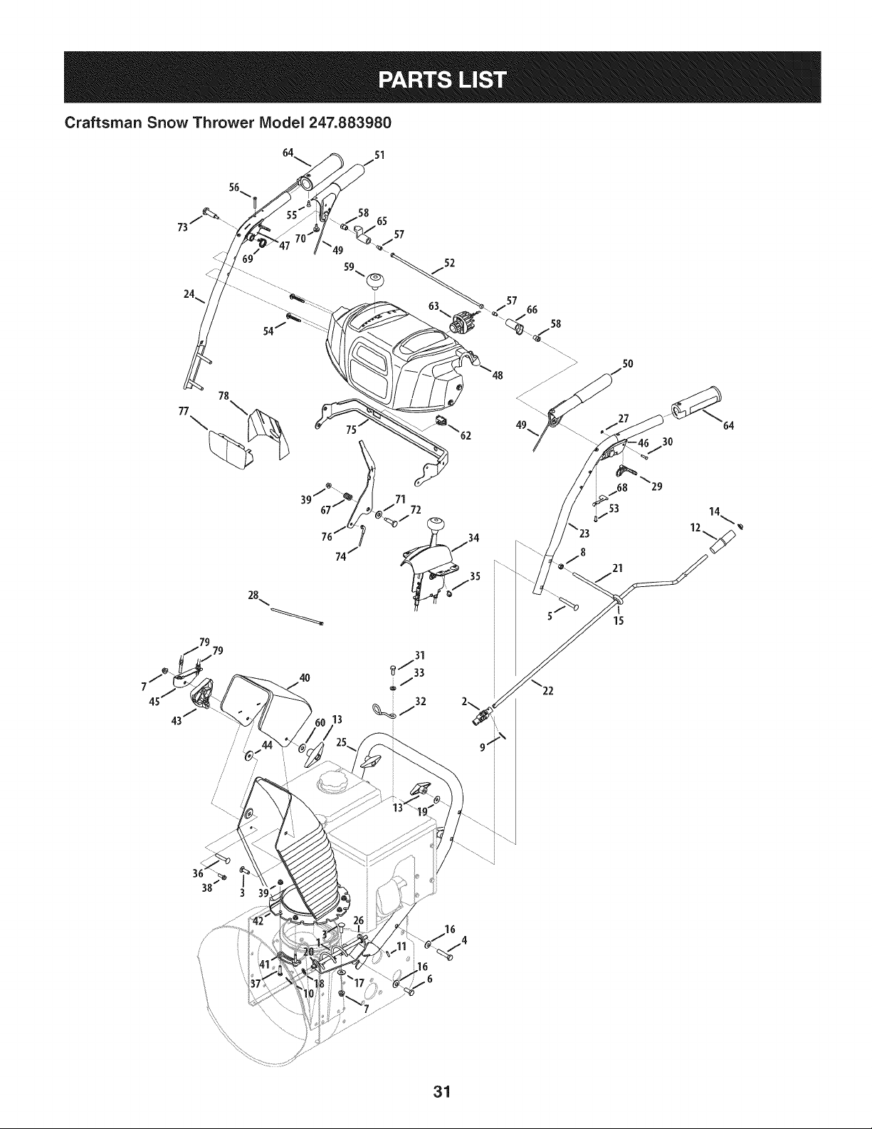
Craftsman Snow Thrower IViodel 247.883980
64 sl
65
57
/
52
77
79
79
/
/' /
57
66
58
5O
21
15
64
3 39
/
/
31
m _ O O
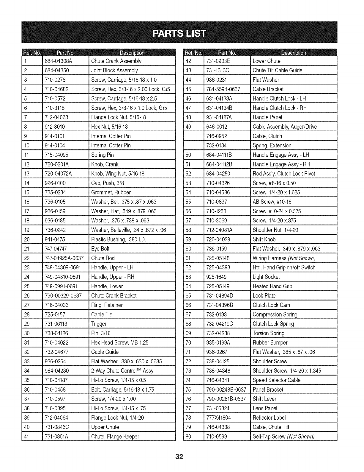
684-04308A ChuteCrankAssembly
2 684-04350 JointBlockAssembly
3 710-0276
4 710-04682
5 710-0572
6 710-3118
7 712-04063
8 912-3010
9 914-0101
10 914-0104
Screw,Carriage,5/16-18x 1.0
Screw,Hex,3/8-16x 2.00 Lock,Gr5
Screw,Carriage,5/16-18x 2.5
Screw,Hex,3/8-16x 1.0Lock,Gr5
FlangeLockNut,5/16-18
HexNut,5/16-18
internalCotterPin
internalCotterPin
11 715-04095 SpringPin
12 720-0201A Knob,Crank
13 720-04072A Knob,WingNut, 5/16-18
14 926-0100 Cap,Push,3/8
15 735-0234 Grommet,Rubber
16 736-0105 Washer,Bel,.375x .87x .063
17 936-0159 Washer,Fiat,.349x .879.063
18 936-0185 Washer,.375x .738x .063
19 736-0242 Washer,Belleville,.34x .872x .06
20 941-0475 PlasticBushing,.380I.D.
21 747-04747 EyeBolt
22 747-04925A-0637 ChuteRod
23 749-04309-0691 Handle,Upper- LH
24 749-04310-0691 Handle,Upper- RH
25 749-0991-0691 Handle,Lower
26 790-00329-0637 ChuteCrankBracket
27 716-04036 Ring,Retainer
28 725-0157 CableTie
29 731-06113 Trigger
30 738-04126 Pin,3/16
31 710-04022 HexHeadScrew,MB1.25
32 732-04677 CableGuide
33 936-0264 FiatWasher,.330x .630x .0635
TM
34 984-04230 J 2-WayChuteControl Assy
35 710-04187 Hi-LoScrew,1/4-15x 0.5
36 710-0458 Bolt,Carriage,5/16-18x 1.75
37 710-0597 Screw,1/4-20x 1.00
38 710-0895 Hi-LoScrew,1/4-15x .75
39 712-04064 FlangeLockNut, 1/4-20
40 731-0846C UpperChute
41 731-0851A Chute,FlangeKeeper
D _ O
731-0903E LowerChute
43 731-1313C ChuteTiltCableGuide
44 936-0231 FiatWasher
45 784-5594-0637 CableBracket
46 631-04133A HandleClutchLock- LH
47 631-04134B HandleClutchLock- RH
48 931-04187A HandlePanel
49 646-0012 CableAssembly,Auger/Drive
746-0952 Cable,Clutch
732-0184 Spring,Extension
50
684-04111B HandleEngageAssy- LH
51 684-04112B HandleEngageAssy- RH
52 684-04250 RodAss'y,ClutchLock Pivot
53 710-04326 Screw,#8-16x 0.50
54 710-04586 Screw,1/4-20x 1.625
55 710-0837 ABScrew,#10-16
56 710-1233 Screw,#10-24x 0.375
57 710-3069 Screw,1/4-20x.375
58
712-04081A ShoulderNut,1/4-20
59 720-04039 ShiftKnob
60 736-0159 FiatWasher,.349x .879x .063
61 725-05148 WiringHarness(Not Shown)
62 725-04393 Htd. HandGripon/off Switch
63 925-1649 LightSocket
64 725-05149 HeatedHandGrip
65 731-04894D LockPlate
66 731-04896B ClutchLockCam
67 732-0193 CompressionSpring
68 732-04219C ClutchLockSpring
69 732-04238 TorsionSpring
70 935-0199A RubberBumper
71 936-0267 FiatWasher,.385x .87x .06
72 738-04125 ShoulderScrew
73 738-04348 ShoulderScrew,1/4-20x 1.345
74 746-04341 SpeedSelectorCable
75 790-00248B-0637 PanelBracket
76 790-00281B-0637 ShiftLever
77 731-05324 LensPanel
78 777X41804 ReflectorLabel
79 746-04338 Cable,ChuteTilt
80 710-0599 Self-TapScrew(NotShown)
32
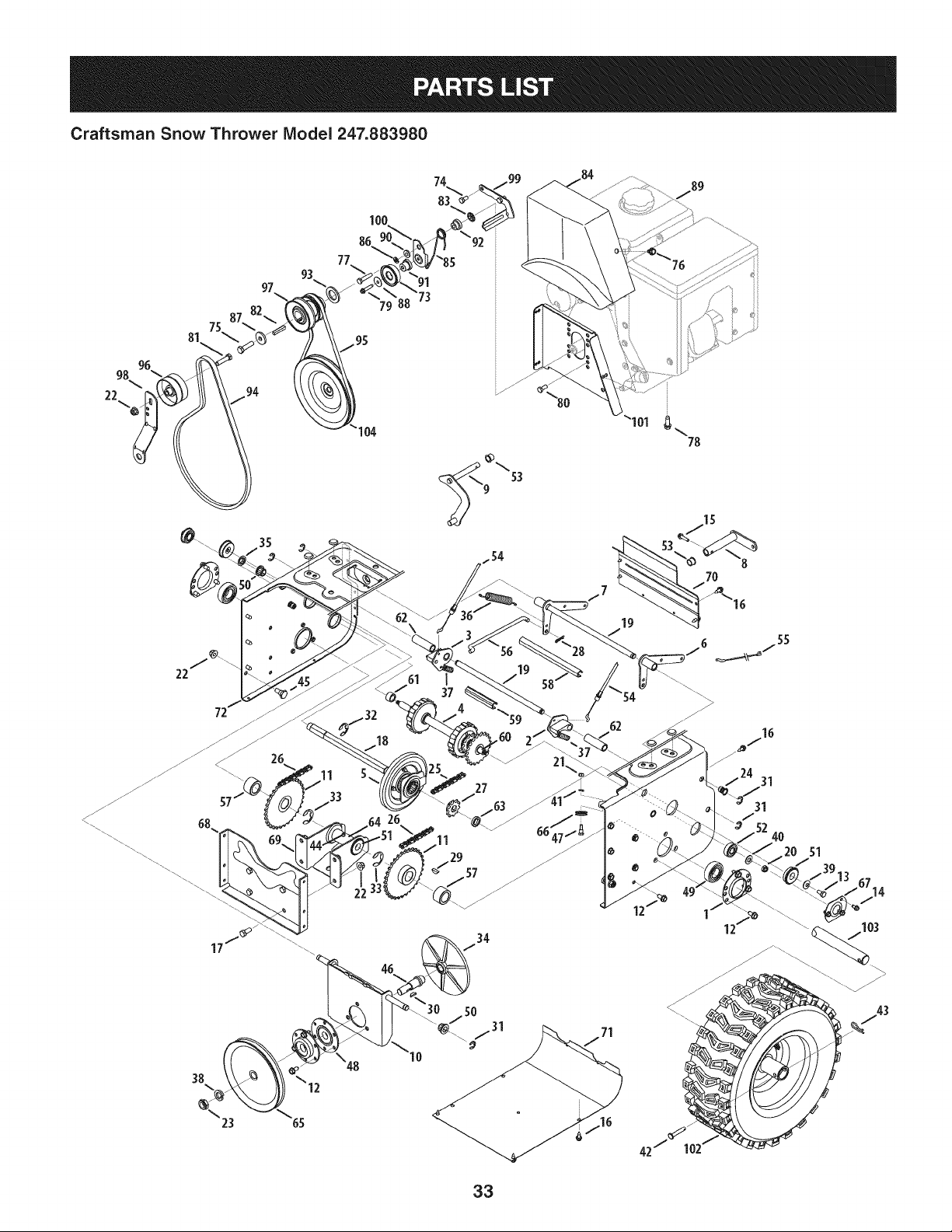
Craftsman Snow Thrower IViodel 247.883980
96
98
22
75
81
77
104
c_
° 19
"54
62
71
78
7O
42
16
4O
51
33
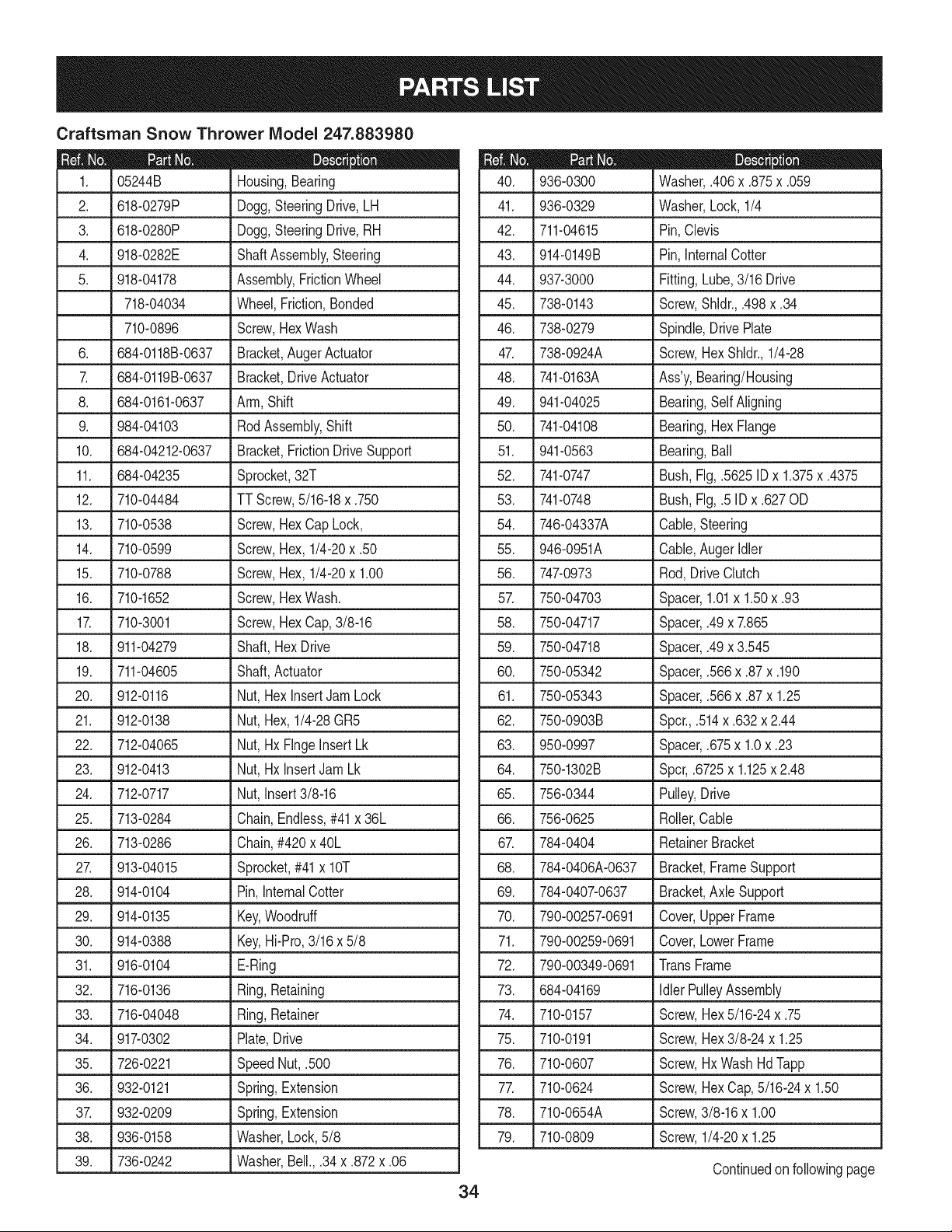
Craftsman Snow Thrower Model 247.883980
|- o o
05244B Housing,Bearing
2. 618-0279P Dogg,SteeringDrive,LH
3. 618-0280P Dogg,SteeringDrive,RH
4. 918-0282E ShaftAssembly,Steering
5. 918-04178 Assembly,FrictionWheel
718-04034 Wheel,Friction,Bonded
710-0896 Screw,HexWash
6. 684-0118B-0637 Bracket,Auger Actuator
7. 684-0119B-0637 Bracket,DriveActuator
8. 684-0161-0637 Arm, Shift
9. 984-04103 RodAssembly,Shift
10. 684-04212-0637 Bracket,FrictionDriveSupport
11. 684-04235 Sprocket,32T
12. 710-04484 TT Screw,5/16-18x .750
13. 710-0538 Screw,HexCap Lock,
14. 710-0599 Screw,Hex,1/4-20x .50
15. 710-0788 Screw,Hex,1/4-20x 1.00
16. 710-1652 Screw,HexWash.
17. 710-3001 Screw,HexCap,3/8-16
18. 911-04279 Shaft,HexDrive
19. 711-04605 Shaft,Actuator
20. 912-0116 Nut, HexInsertJam Lock
21. 912-0138 Nut, Hex,1/4-28GR5
22. 712-04065 Nut, HxFlngeInsertLk
23. 912-0413 Nut, HxInsertJamLk
24. 712-0717 Nut, Insert3/8-16
25. 713-0284 Chain,Endless,#41x 36L
26. 713-0286 Chain,#420x 40L
27. 913-04015 Sprocket,#41 x lOT
28. 914-0104 Pin, InternalCotter
29. 914-0135 Key,Woodruff
30. 914-0388 Key,Hi-Pro,3/16x 5/8
31. 916-0104 E-Ring
32. 716-0136 Ring,Retaining
33. 716-04048 Ring,Retainer
34. 917-0302 Plate,Drive
35. 726-0221 SpeedNut,.500
36. 932-0121 Spring,Extension
37. 932-0209 Spring, Extension
38. 936-0158 Washer,Lock,5/8
39. 736-0242 Washer, Bell., .34 x .872 x .06
D = O e
936-0300 Washer,.406x .875x .059
41. 936-0329 Washer,Lock, 1/4
42. 711-04615 Pin,Clevis
43. 914-0149B Pin,InternalCotter
44. 937-3000 Fitting,Lube,3/16Drive
45. 738-0143 Screw,Shldr.,.498x .34
46. 738-0279 Spindle,DrivePlate
47. 738-0924A Screw,HexShldr.,1/4-28
48. 741-0163A Ass'y, Bearing/Housing
49. 941-04025 Bearing,SelfAligning
50. 741-04108 Bearing,HexFlange
51. 941-0563 Bearing,Ball
52. 741-0747 Bush,Fig,.5625ID x 1.375x .4375
53. 741-0748 Bush,Fig,.5 IDx .627OD
54. 746-04337A Cable,Steering
55. 946-0951A Cable,AugerIdler
56. 747-0973 Rod,DriveClutch
57. 750-04703 Spacer,1.01x 1.50x .93
58. 750-04717 Spacer,.49x 7.865
59. 750-04718 Spacer,.49x 3.545
60. 750-05342 Spacer,.566x .87x .190
61. 750-05343 Spacer,.566x .87x 1.25
62. 750-0903B Spcr.,.514x .632x 2.44
63. 950-0997 Spacer,.675x 1.0x .23
64. 750-1302B Spcr,.6725x 1.125x 2.48
65. 756-0344 Pulley,Drive
66. 756-0625 Roller,Cable
67. 784-0404 RetainerBracket
68. 784-0406A-0637 Bracket,FrameSupport
69. 784-0407-0637 Bracket,Axle Support
70. 790-00257-0691 Cover,UpperFrame
71. 790-00259-0691 Cover,LowerFrame
72. 790-00349-0691 TransFrame
73. 684-04169 IdlerPulleyAssembly
74. 710-0157 Screw,Hex5/16-24x .75
75. 710-0191 Screw,Hex3/8-24 x 1.25
76. 710-0607 Screw,HxWashHd lapp
77. 710-0624 Screw,HexCap,5/16-24x 1.50
78. 710-0654A Screw,3/8-16x 1.00
79. 710-0809 Screw,1/4-20x 1.25
Continuedon followingpage
34
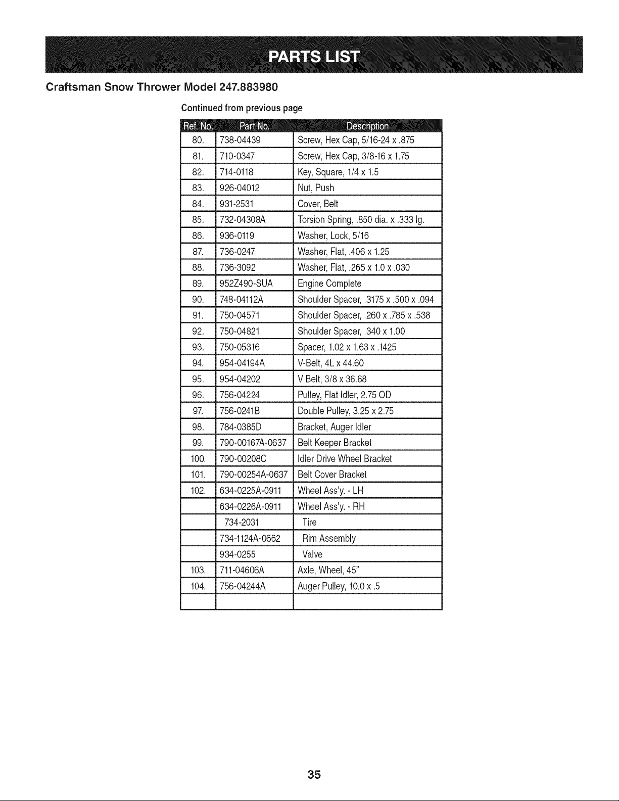
Craftsman Snow Thrower IViodel 247.883980
Continuedfrom previouspage
|= 0 =
738-04439
81. 710-0347
82. 714-0118
83. 926-04012
84. 931-2531
85. 732-04308A
86. 936-0119
87. 736-0247
88. 736-3092
89. 952Z490-SUA
90. 748-04112A
91. 750-04571
92. 750-04821
93. 750-05316
94. 954-04194A
95. 954-04202
96. 756-04224
Screw,HexCap,5/16-24x .875
Screw,HexCap,3/8-16x 1.75
Key,Square,1/4x 1.5
Nut, Push
Cover,Belt
TorsionSpring,.850dia. x .333Ig.
Washer,Lock,5/16
Washer,Flat,.406x 1.25
Washer,Flat,.265x 1.0x .030
EngineComplete
ShoulderSpacer,.3175x .500x .094
ShoulderSpacer,.260x .785x .538
ShoulderSpacer,.340x 1.00
Spacer,1.02x 1.63x .1425
V-Belt,4Lx 44.60
V Belt, 3/8 x 36.68
Pulley,FlatIdler,2.75OD
97. 756-0241B DoublePulley,3.25x 2.75
98. 784-0385D Bracket,AugerIdler
99. 790-00167A-0637 Belt KeeperBracket
100. 790-00208C Idler DriveWheelBracket
101. 790-00254A-0637 Belt CoverBracket
102. 634-0225A-0911 WheelAss'y.- LH
634-0226A-0911 WheelAss'y.- RH
734-2031 Tire
734-1124A-0662 RimAssembly
934-0255 Valve
103. 711-04606A Axle, Wheel,45"
104. 756-04244A AugerPulley,10.0x .5
35
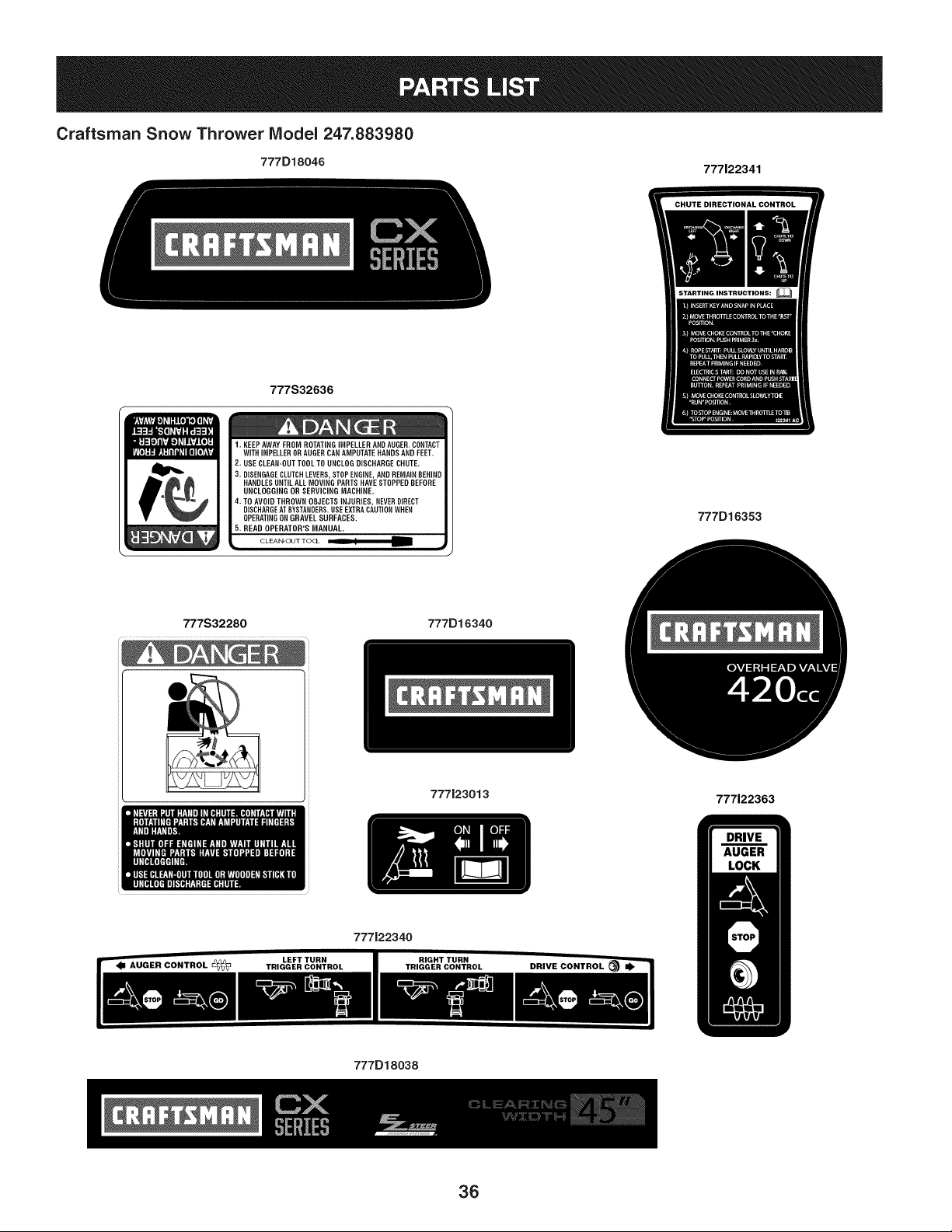
Craftsman Snow Thrower Model 247.883980
777D18046 777122341
777S32636
1. KEEP AWAY FROM ROTATING IMPELLER ANDAUGER. CONTACT
WITH iMPELLEROR AUGERCANAMPUTATE HANDS AND FEET.
2. USE CLEAN-OUT TOOL TO UNCLOG DISCHARGE CHUTE.
3. DISENGAGECLUTCHLEVERS,STOP ENGINE,AND REMAIN 8ER]ND
HANDLES UNTIL ALL MOVING PARTS NME STOPPED BEFORE
UNCLOGGING OR SERVICING MACHINE.
4. TO AVOID THROWN OBJECTS iNJURIES, NEVERDIRECT
DISCHARGEAT BYSTANDERS.USE EXTRA CAUTIONWHEN
OPERATINGON GRAVEL SURFACES.
5. READ OPERATOR'S MANUAL.
777D16353
777S32280 777D16340
777J23013
777122363
777122340
777D18038
36
LOCK
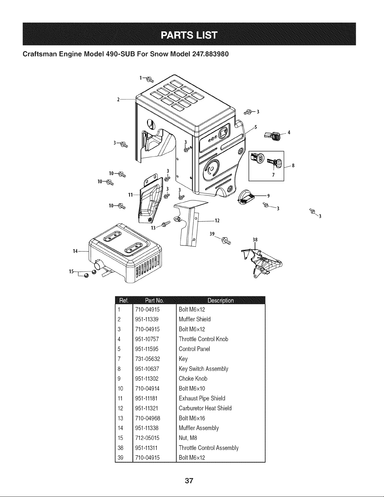
Craftsman Engine Model 490=SUB For Snow Model 247.883980
m
1
2
3
4
5
7
8
9
10
11
12
13
14
15
38
39
710-04915
951-11339
710-04915
951-10757
951-11595
731-05632
951-10637
951-11302
710-04914
951-11181
951-11321
710-04968
951-11338
712-05015
951-11311
710-04915
D = I! II
Bolt M6x12
MufflerShield
Bolt M6x12
ThrottleControlKnob
ControlPanel
Key
KeySwitchAssembly
ChokeKnob
Bolt M6xlO
ExhaustPipeShield
CarburetorHeatShield
Bolt M6x16
MufflerAssembly
Nut, M8
ThrottleControlAssembly
Bolt M6x12
37
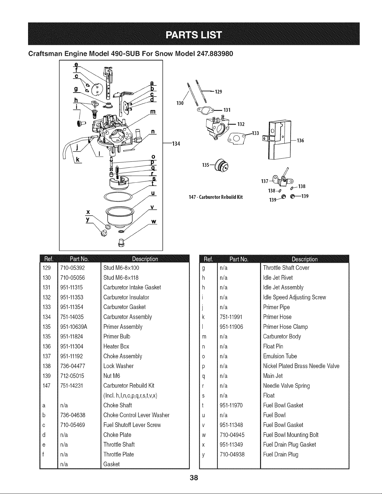
Craftsman Engine IViodel 490-SUB For Snow IViodel 247.883980
X
Y
V
130
--134
_131
33
147- CarburetorRebuildKit
137138_0_ 138
139_ 0--139
m
129
130
131
132
133
134
135
135
136
137
138
139
147
a
b
C
d
e
f
710-05392
710-05056
951-11315
951-11353
951-11354
751-14035
951-10639A
951-11824
951-11304
951-11192
736-04477
712-05015
751-14231
n/a
736-04638
710-05469
n/a
n/a
n/a
n/a
D = O
StudM6-8x100
StudM6-8x118
CarburetorIntakeGasket
CarburetorInsulator
CarburetorGasket
CarburetorAssembly
PrimerAssembly
PrimerBulb
HeaterBox
ChokeAssembly
LockWasher
NutM6
CarburetorRebuildKit
(Incl.h,l,n,o,p,q,r,s,t,v,x)
ChokeShaft
ChokeControlLeverWasher
FuelShutoffLeverScrew
ChokePlate
ThrottleShaft
ThrottlePlate
Gasket
m
g
h
h
I
J
k
I
m
n
o
P
q
r
s
t
U
V
W
X
Y
n/a
n/a
n/a
n/a
n/a
751-11991
951-11906
n/a
n/a
n/a
n/a
n/a
n/a
n/a
951-11970
n/a
951-11348
710-04945
951-11349
710-04938
D = O e
ThrottleShaft Cover
IdleJet Rivet
IdleJet Assembly
IdleSpeedAdjustingScrew
PrimerPipe
PrimerHose
PrimerHoseClamp
CarburetorBody
FloatPin
EmulsionTube
NickelPlatedBrassNeedleValve
MainJet
NeedleValveSpring
Float
FuelBowlGasket
FuelBowl
FuelBowlGasket
FuelBowlMountingBolt
FuelDrainPlugGasket
FuelDrainPlug
38
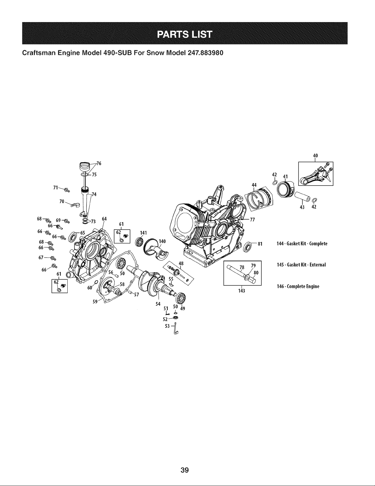
Craftsman Engine IViodel 490=SUB For Snow IViodel 247.883980
61
141
140
44
42
4O
I
43 42
144- GasketKit-Complete
145-GasketKit-External
146-CompleteEngine
49
39
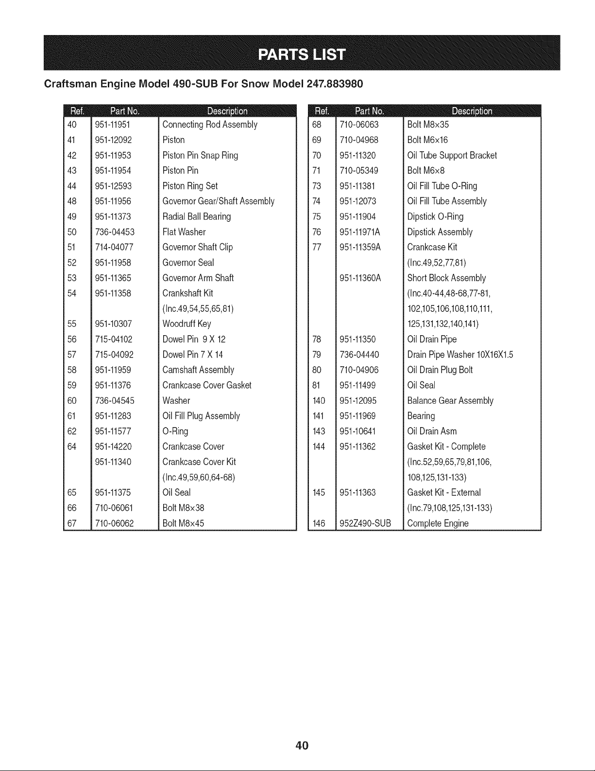
Craftsman Engine IViodel 490=SUB For Snow IViodel 247.883980
m
4O
41
42
43
44
48
49
5O
51
52
53
54
55
56
57
58
59
60
61
62
64
65
66
67
951-11951
951-12092
951-11953
951-11954
951-12593
951-11956
951-11373
736-04453
714-04077
951-11958
951-11365
951-11358
951-10307
715-04102
715-04092
951-11959
951-11376
736-04545
951-11283
951-11577
951-14220
951-11340
951-11375
710-06061
710-06062
m = O Q
ConnectingRodAssembly
Piston
PistonPinSnapRing
PistonPin
PistonRingSet
GovernorGear/ShaftAssembly
RadialBall Bearing
FlatWasher
GovernorShaftClip
GovernorSeal
GovernorArm Shaft
CrankshaftKit
(Inc.49,54,55,65,81)
WoodruffKey
DowelPin 9 X 12
DowelPin7 X 14
CamshaftAssembly
CrankcaseCoverGasket
Washer
Oil FillPlug Assembly
O-Ring
CrankcaseCover
CrankcaseCoverKit
(Inc.49,59,60,64-68)
Oil Seal
Bolt M8x38
Bolt M8x45
m
68
69
7O
71
73
74
75
76
77
78
79
8O
81
140
141
143
144
145
146
710-06063
710-04968
951-11320
710-05349
951-11381
951-12073
951-11904
951-11971A
951-11359A
951-11360A
951-11350
736-04440
710-04906
951-11499
951-12095
951-11969
951-10641
951-11362
951-11363
952Z490-SUB
D = W O
Bolt M8x35
Bolt M6x16
OilTubeSupportBracket
Bolt M6x8
Oil FillTubeO-Ring
Oil FillTubeAssembly
DipstickO-Ring
DipstickAssembly
CrankcaseKit
(Inc.49,52,77,81)
ShortBlockAssembly
(Inc.40-44,48-68,77-81,
102,105,106,108,110,111,
125,131,132,140,141)
Oil DrainPipe
DrainPipeWasher 10X16X1.5
Oil DrainPlug Bolt
OilSeal
BalanceGearAssembly
Bearing
Oil DrainAsm
GasketKit- Complete
(Inc.52,59,65,79,81,106,
108,125,131-133)
GasketKit- External
(Inc.79,108,125,131-133)
CompleteEngine
4O
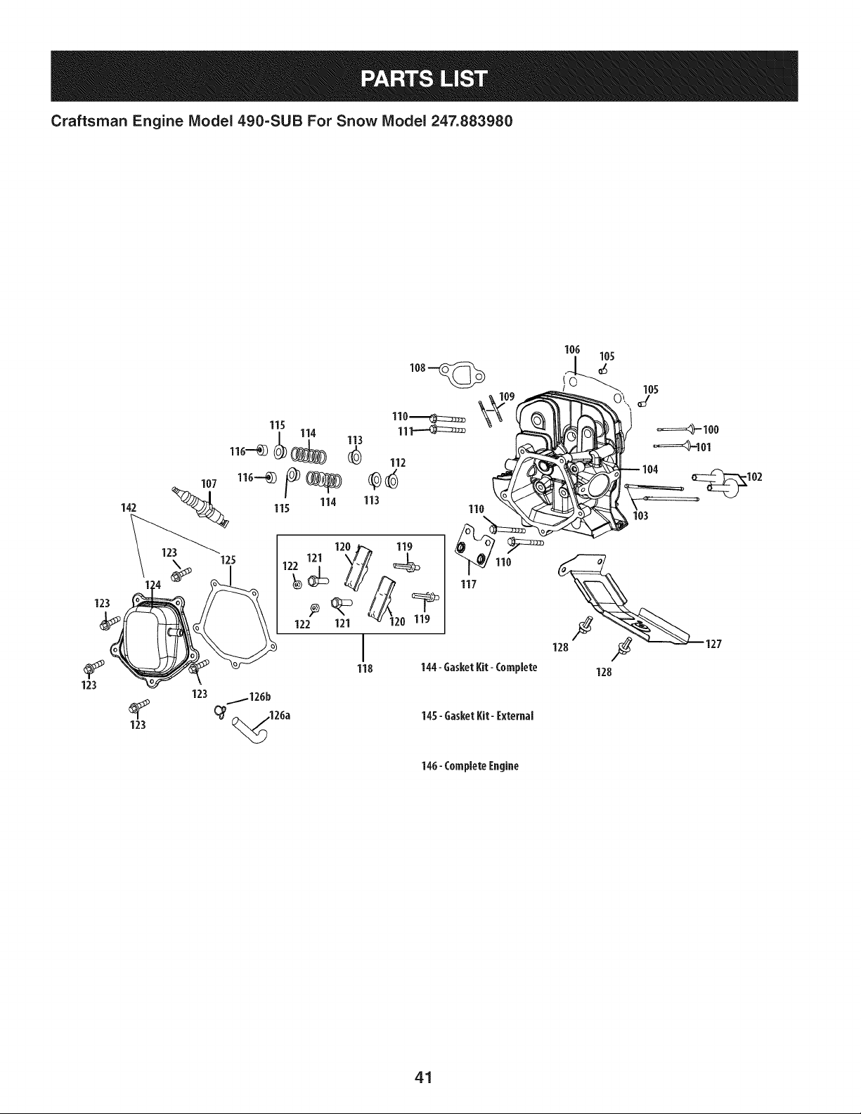
Craftsman Engine Model 490=SUB For Snow Model 247.883980
142
123
123
123
123 _126b
(_ ,126a 14S- GasketKit- [xternal
146- Complete[ngine
41
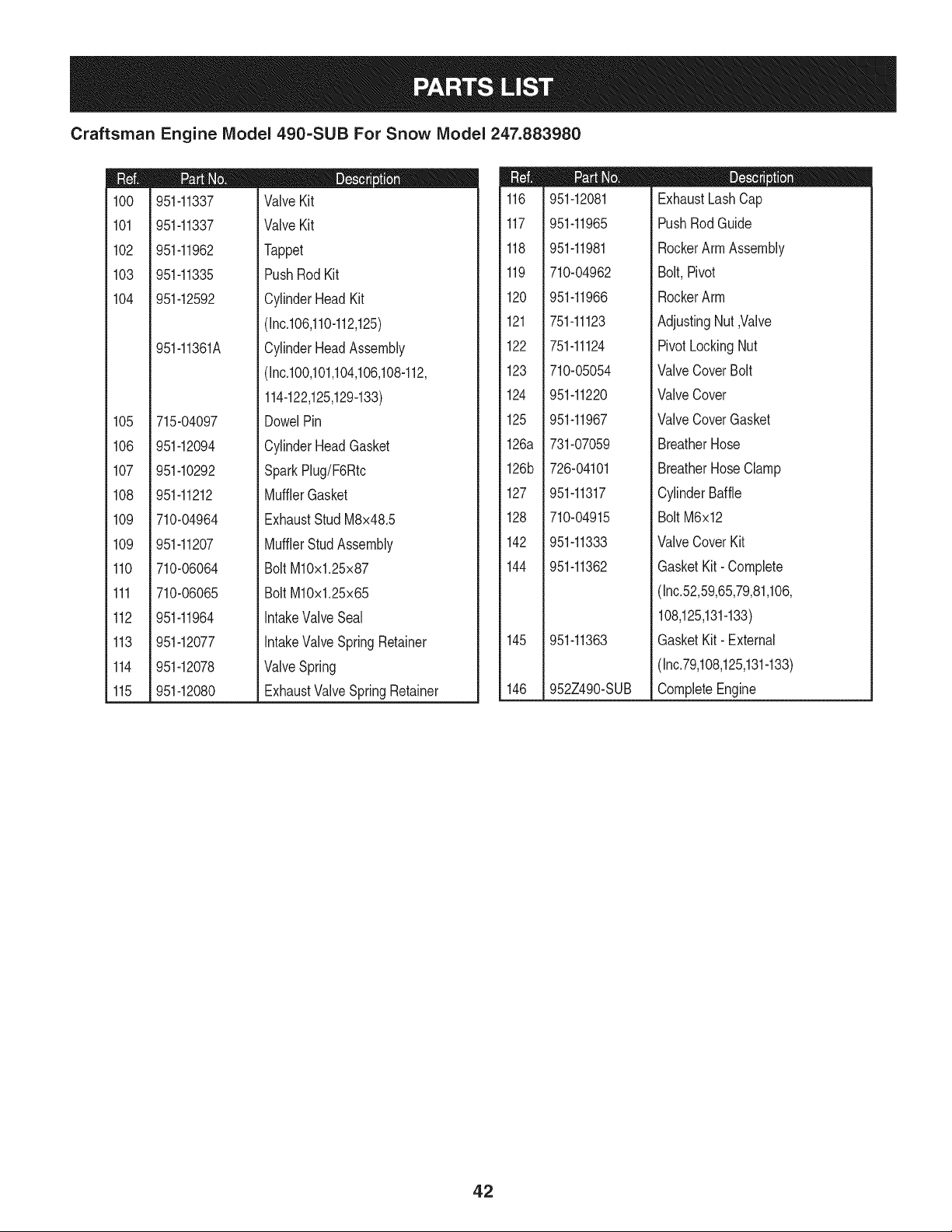
Craftsman Engine IViodel 490-SUB For Snow IViodel 247.883980
m
1CO
101
102
103
104
105
106
107
108
109
109
110
111
112
113
114
115
951-11337
951-11337
951-11962
951-11335
951-12592
951-11361A
715-04097
951-12094
951-10292
951-11212
710-04964
951-11207
710-06064
710-06065
951-11964
951-12077
951-12078
951-12080
D = O 0
ValveKit
ValveKit
Tappet
PushRodKit
CylinderHeadKit
(Inc.106,110-112,125)
CylinderHeadAssembly
(Inc.100,101,104,106,108-112,
114-122,125,129-133)
DowelPin
CylinderHeadGasket
SparkPlug/F6Rtc
MufflerGasket
ExhaustStudM8x48.5
MufflerStudAssembly
BoltM10x1.25x87
BoltM10x1.25x65
IntakeValveSeal
IntakeValveSpringRetainer
ValveSpring
ExhaustValveSpringRetainer
m
116
117
118
119
120
121
122
123
124
125
126a
126b
127
128
142
144
145
146
951-12081
951-11965
951-11981
710-04962
951-11966
751-11123
751-11124
710-05054
951-11220
951-11967
731-07059
726-04101
951-11317
710-04915
951-11333
951-11362
951-11363
952Z490-SUB
D = O O
ExhaustLashCap
PushRodGuide
RockerArmAssembly
Bolt,Pivot
RockerArm
AdjustingNut,Valve
PivotLockingNut
ValveCoverBolt
ValveCover
ValveCoverGasket
BreatherHose
BreatherHoseClamp
CylinderBaffle
BoltM6x12
ValveCoverKit
GasketKit- Complete
(Inc.52,59,65,79,81,106,
108,125,131-133)
GasketKit- External
(Inc.79,108,125,131-133)
CompleteEngine
42
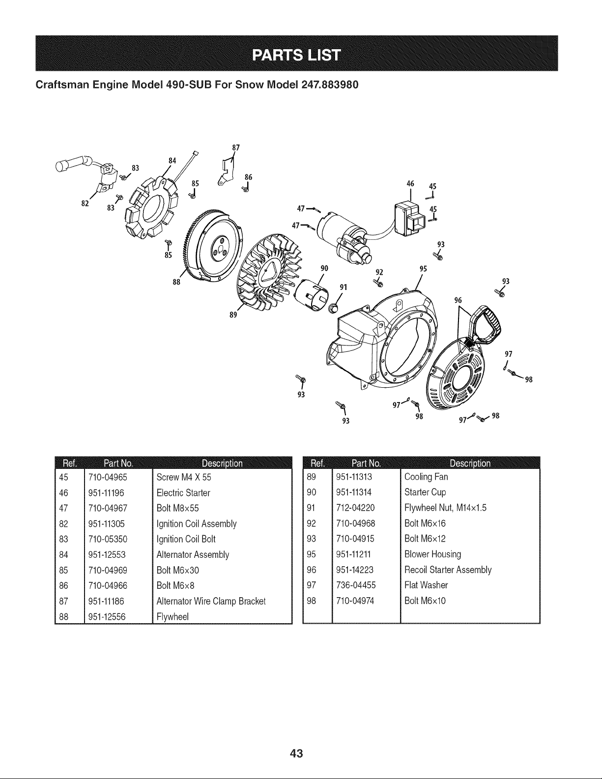
Craftsman Engine IViodel 490=SUB For Snow IViodel 247.883980
82
83
8s /
8
/
89
98
m
45
46
47
82
83
84
85
86
87
88
710-04965
951-11196
710-04967
951-11305
710-05350
951-12553
710-04969
710-04966
951-11186
951-12556
D = O
ScrewM4X 55
ElectricStarter
Bolt M8x55
IgnitionCoilAssembly
IgnitionCoil Bolt
AlternatorAssembly
Bolt M6x30
Bolt M6x8
AlternatorWireClamp Bracket
Flywheel
m
89
90
91
92
93
95
96
97
98
951-11313
951-11314
712-04220
710-04968
710-04915
951-11211
951-14223
736-04455
710-04974
D = O
CoolingFan
StarterCup
FlywheelNut, M14x1.5
Bolt M6x16
Bolt M6x12
BlowerHousing
RecoilStarterAssembly
FlatWasher
Bolt M6xlO
43
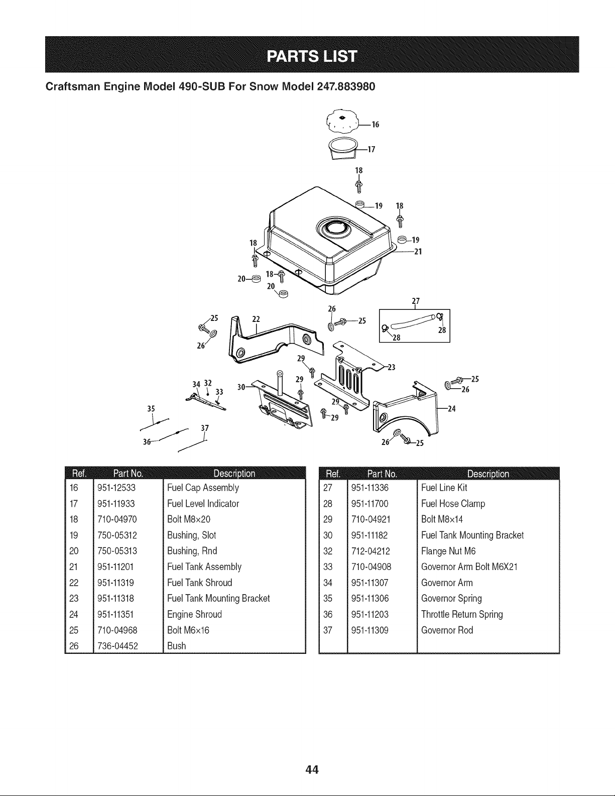
Craftsman Engine IViodel 490=SUB For Snow IViodel 247.883980
m
16
17
18
19
2O
21
22
23
24
25
26
(_17
18
"_ 27
26
I
34 32
24
951-12533
951-11933
710-04970
750-05312
750-05313
951-11201
951-11319
951-11318
951-11351
710-04968
736-04452
D = O
FuelCap Assembly
FuelLevelIndicator
BoltM8x20
Bushing,Slot
Bushing,Rnd
FuelTankAssembly
FuelTankShroud
FuelTankMountingBracket
EngineShroud
BoltM6x16
Bush
m
27
28
29
30
32
33
34
35
36
37
951-11336
951-11700
710-04921
951-11182
712-04212
710-04908
951-11307
951-11306
951-11203
951-11309
m = O O
FuelLine Kit
FuelHose Clamp
Bolt M8x14
FuelTankMountingBracket
FlangeNut M6
GovernorArm Bolt M6X21
GovernorArm
GovernorSpring
ThrottleReturnSpring
GovernorRod
44
MTD CONSUMER GROUP INC (MTD), the California Air Resources Board (CARB)
and the United States Environment Protection Agency (U. S. EPA)
Emission Control System Warranty Statement
(Owner's Defect Warranty Rights and Obligations)
EMISSIONCONTROLSYSTEMCOVERAGEIS APPLICABLETOCERTIFIEDENGINESPURCHASEDINCALIFORNIAIN 2005 ANDTHERE-
AFTER,WHICHARE USEDINCALIFORNIA,ANDTO CERTIFIEDMODELYEAR2005ANDLATERENGINESWHICHARE PURCHASEDAND
USEDELSEWHEREIN THE UNITEDSTATES.
Californiaandelsewherein the UnitedStatesEmissionControlDefectsWarrantyCoverage
The CaliforniaAir ResourcesBoard(CARB),U. S. EPAandMTDare pleasedto explaintheemissionscontrolsystemwarrantyonyour modelyear
2006andlatersmalloff-roadengine.In California,new smalloff-roadenginesmustbe designed,builtand equippedto meet theStatesanti-smog
standards.Elsewherein the UnitedStates,newnon-road,spark-ignitionenginescertifiedfor model2005and later,mustmeetsimilarstandardsset
forthby the U.S. EPA.MTDmustwarrantythe emissioncontrolsystemonyourenginefor the periodof time listed below,providedtherehasbeen
noabuse,neglector impropermaintenanceof your smalloff-roadengine.
Youremissioncontrolsystemmayincludepartssuch as the carburetor,fuel-injectionsystem,the ignitionsystem,andcatalyticconverter,fueltanks,
fuel lines,fuel caps,valves,canisters,filters,vaporhoses,clamps,connectors,and otherassociatedemission-relatedcomponents.
Wherea warrantableconditionexists,MTDwill repairyoursmall off-roadengineat no cost to yourincludingdiagnosis,partsand labor.
MANUFACTURER'S WARRANTY COVERAGE:
Thisemissionscontrolsystemis warrantedfor twoyears.If anyemission-relatedpart on yourengineis defective,the part will berepairedor
replacedby MTD.
OWNER'S WARRANTY RESPONSIBILITIES:
As the smalloff-roadengineowner,youare responsibleforthe performanceof the requiredmaintenancelisted in your Owner'sManual.MTD
recommendsthatyou retainall yourreceiptscoveringmaintenanceson yoursmalloff-roadengine,but MTDcan not denywarrantysolelyfor the
lackof receiptsor foryour failureto ensurethe performanceto allscheduledmaintenance.
As the smalloff-roadengineowner,youshouldhoweverbe awarethat MTDmaydenyyour warrantycoverageif yoursmall off-roadengineorpart
hasfaileddue toabuse,neglect,impropermaintenanceor unapprovedmodifications.
Youare responsiblefor presentingyour smalloff-roadengineto an AuthorizedMTDServiceDealeras soonas a problemexists.Thewarranted
repairsshouldbe completedin a reasonableamountof time,notto exceed30 days.
Ifyou haveanyquestionsregardingyourwarrantyrightsand responsibilities,you shouldcontacta MTDServiceRepresentativeat 1-800-800-7310
andaddressis MTDCONSUMERGROUP,RO. Box361131,ClevelandOH,44136-0019.
DEFECTS WARRANTY REQUIREMENTS FOR 1995 AND LATER SMALL OFF-ROAD ENGINES:
Thissectionappliesto 1995and later smalloff-roadengines.The warrantyperiodbeginson the datethe engineor equipmentis deliveredto an
ultimatepurchaser.
(a) GeneralEmissionsWarrantyCoverage_
MTDmustwarrantto the ultimatepurchaserand eachsubsequentpurchaserthat the engineis:
(1)Designed,built,andequippedsoas to conformwith all applicableregulationsadoptedby the AirResourcesBoardpursuantto its authorityin
Chapters1and2,Part5, Division26of the HealthandSafetyCode;and
(2) Freefrom defectsin materialsandworkmanshipthat causethe failureof a warrantedpart to be identicalin all materialrespectsto the partas
describedin theengine manufacturer'sapplicationfor certificationfora periodof twoyears.
.(b)The warrantyonemissions-relatedpartswill be interpretedas follows:
(1)Anywarrantedpart thatis not scheduledfor replacementas requiredmaintenancein the writteninstructionsrequiredby Subsection(c)
mustbe warrantedfor the warrantyperioddefinedin Subsection(a)(2). If any suchpartfails duringthe periodof warrantycoverage,it mustbe
repairedor replacedby MTDaccordingto Subsection(4) below.Anysuchpart repairedor replacedunderthewarrantymustbe warrantedfor
the remainingwarrantyperiod.
(2)Any warrantedpartthat is scheduledonlyfor regularinspectionin the writteninstructionsrequiredby Subsection(c) must bewarrantedfor
thewarrantyperioddefinedin Subsection(a)(2).A statementin such writteninstructionsto the effectof "repairor replaceas necessary"will
not reducethe periodof warrantycoverage.Anysuchpart repairedor replacedunderwarrantymustbe warrantedforthe remainingwarranty
period.
(3) Anywarrantedpartthat whichis scheduledfor replacementas requiredmaintenancein the writteninstructionsrequiredby Subsection(c)
mustbe warrantedfor the periodof timepriorto the first scheduledreplacementpointforthat part.Ifthe part failspriorto thefirst scheduled
replacement,the part mustbe repairedor replacedby MTDaccordingto Subsection(4) below.Any suchpart repairedor replacedunder
warrantymustbe warrantedfor the remainderof the periodpriorto the first scheduledreplacementpointfor the part.
(4) Repairor replacementof any warrantedpartunderthewarrantyprovisionsof thisarticlemustbe performedat no chargeto the ownerat a
warrantystation.
(5) Notwithstandingthe provisionsof Subsection(4) above,warrantyservicesor repairsmustbe providedat all MTDdistributioncentersthat
arefranchisedto servicethe subjectengines.
(6)Theownermustnotbechargedfordiagnosticlaborthatleadstothedeterminationthatawarrantedpartisinfactdefective,providedthat
suchdiagnosticworkisperformedatawarrantystation.
(7)Theenginemanufacturerisliablefordamagestootherenginecomponentsproximatelycausedbyafailureunderwarrantyofanywarranted
part.
(8)Throughouttheengine'swarrantyperioddefinedinSubsection(a)(2),MTDwillmaintainasupplyofwarrantedpartssufficienttomeetthe
expecteddemandforsuchparts.
(9)Anyreplacementpartmaybeusedintheperformanceofanywarrantymaintenanceorrepairsandmustbeprovidedwithoutchargetothe
owner.SuchusewillnotreducethewarrantyobligationsofMTD.
(10)Add-onormodifiedpartsthatarenotexemptedbytheAirResourcesBoardmaynotbeused.Theuseofanynon-exemptedadd-onor
modifiedpartsshallbegroundsfordisallowingawarrantyclaimmadeinaccordancewiththisarticle.Theenginemanufacturershallnotbe
liableunderthisarticletowarrantfailuresofwarrantedpartscausedbytheuseofnon-exemptedadd-onormodifiedpart.
(c) MTDwill includea copyof the followingemissionwarrantypartslistwitheach newengine,usingthoseportionsof the listapplicableto the
e__&gine.
(1)FuelMeteringSystem
• Coldstart enrichmentsystem(soft choke)
,,Carburetorandinternalparts
• Fuel Pump
• FuelTank
(2)Air InductionSystem
• Aircleaner
• Intakemanifold
(3) IgnitionSystem
• Sparkplug(s)
• MagnetoIgnitionSystem
(4)ExhaustSystem
Catalyticconverter
• SAI (Reedvalve)
(5) MiscellaneousItemsUsedin AboveSystem
Vacuum,temperature,position,timesensitivevalvesand switches
Connectorsandassemblies
(6) Evaporativecontrol
• Fuel Hosecertifiedfor ARBevaporativeemissionof 2006.
• Fuel HoseClamps
Tetheredfuel cap
Carboncanister
• Vaporlines
GD0C-100174Rev.B
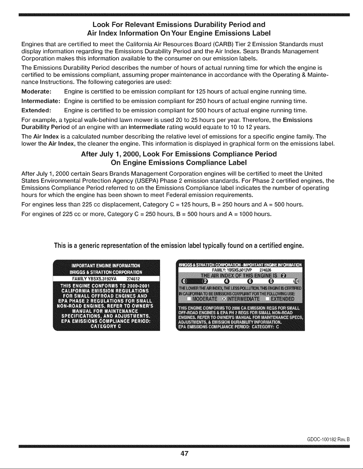
Look For Relevant Emissions Durability Period and
Air index information On Your Engine Emissions Label
Engines that are certified to meet the California Air Resources Board (CARB) Tier 2 Emission Standards must
display information regarding the Emissions Durability Period and the Air Index. Sears Brands Management
Corporation makes this information available to the consumer on our emission labels.
The Emissions Durability Period describes the number of hours of actual running time for which the engine is
certified to be emissions compliant, assuming proper maintenance in accordance with the Operating & Mainte-
nance Instructions. The following categories are used:
Moderate: Engine is certified to be emission compliant for 125 hours of actual engine running time.
Intermediate: Engine is certified to be emission compliant for 250 hours of actual engine running time.
Extended: Engine is certified to be emission compliant for 500 hours of actual engine running time.
For example, a typical walk-behind lawn mower is used 20 to 25 hours per year. Therefore, the Emissions
Durability Period of an engine with an intermediate rating would equate to 10 to 12 years.
The Air index is a calculated number describing the relative level of emissions for a specific engine family. The
lower the Air Index, the cleaner the engine. This information is displayed in graphical form on the emissions label.
After July 1,2000, Look For Emissions Compliance Period
On Engine Emissions Compliance Label
After July 1, 2000 certain Sears Brands Management Corporation engines will be certified to meet the United
States Environmental Protection Agency (USEPA) Phase 2 emission standards. For Phase 2 certified engines, the
Emissions Compliance Period referred to on the Emissions Compliance label indicates the number of operating
hours for which the engine has been shown to meet Federal emission requirements.
For engines less than 225 cc displacement, Category C = 125 hours, B = 250 hours and A = 500 hours.
For engines of 225 cc or more, Category C = 250 hours, B = 500 hours and A = 1000 hours.
This is a generic representation of the emission label typically found on a certified engine.
FAMILYYBSXS.3192VA 274812
GDOC-100182Rev.B
47
Congratulations on making a smart purchase. Your new Craftsman® product is designed and
manufactured for years of dependable operation. But like all products, it may require repair
from time to time. That's when having a Repair Protection Agreement can save you money and
aggravation.
Here's what the Repair Protection Agreement* includes:
[] Expert service by our 10,000 professional repair specialists
[] Unlimited service and no charge for parts and labor on all covered repairs
[] Product replacement up to $1500 if your covered product can't be fixed
[] Discount of 25% from regular price of service and related installed parts not covered by the
agreement; also, 25% off regular price of preventive maintenance check
[] Fast help by phone - we call it Rapid Resolution - phone support from a Sears representative.
Think of us as a "talking owner's manual."
Once you purchase the Repair Protection Agreement, a simple phone call is all that it takes for you
to schedule service. You can call anytime day or night, or schedule a service appointment online.
The Repair Protection Agreement is a risk-free purchase. If you cancel for any reason during the
product warranty period, we will provide a full refund. Or, a prorated refund anytime after the
product warranty period expires. Purchase your Repair Protection Agreement today!
Some limitations and exclusions apply. For prices and additional information in the U.S.A.
call 1=800=827=6655.
*Coverage in Canada varies on some items. For full details call Sears Canada at 1=800=361=
6665.
Sears Installation Service
For Sears professional installation of home appliances, garage door openers, water heaters, and
other major home items, in the U.S.A. or Canada call 1=800=4=MY=HOME®.
48
Declaraci6n de garantia ............................ Pagina 49
Practicas operaci6n seguras ..................... Pagina 50
Montaje ...................................................... Pagina 54
Operaci6n .................................................. Pagina 59
Servicio y Mantenimiento .......................... Pagina 64
Almacenamiento fuera de temporada ....... Pagina 72
Soluci6n de problemas .............................. Pagina 73
Etiquetas de seguridad .............................. Pagina 7
Lista de piezas ........................................... Pagina 29
Acuerdo de protecci6n para reparaciones.. Pagina 79
NOmero de servicio ................................... atras pagina
CRAFTSMAN PROFESIONAL DE DOS Al_iOS DE GARANTiA
PORDOSANOSa partirdela fechade compra,este productoestAgarantizadocontracualquierdefectode materialo manode obra.Un
productodefectuosorecibirAla reparaci6no lasustituci6nsi la reparaci6nno estAdisponible.
Estagaranfiase aplicas61oparaun a_o a partirde lafechade comprasi este productose ha utilizadoalguna vez,mientrasque la prestaci6nde
servicioscomercialeso si se alquilaa otra persona.
Paraobtenerinformaci6ndetalladacoberturadela garanfiaparaobtenerla reparaci6no sustituci6ngratuita,visiteel sitio web:
www.craftsman.com.
Esta garantiacubre_nicarnente los defectos en rnaterialesy rnanode obra. Lacobertura de garantiano incluye:
• Elementosreutilizablesquepuedengastarseporel uso normaldentrodel periodode garanfia,incluyendoperonolimitadoalas barrenas,
palasbarrena,cortadoresde la deriva,zapatosantideslizantes,placade raspado,pasadoresde seguridad,la buj[a,el filtrodeaire,
cinturones,y el filtrode aceite.
• Los serviciosde mantenimiento,cambiosde aceite,o puestasa punto.
• Neum_ticosde reemplazoo reparaci6nde pinchazoscausadospor objetosexternos,talescomoclavos,espinas,toconeso vidrio.
• Neumaticoo ruedade repuestoo reparaci6nresultantesdel desgastenormal,accidenteo realfuncionamientoo mantenimiento.
• Reparacionesnecesariasdebido al abusodel operador,incluyendopero no limitadoa da_oscausadospor excesodevelocidaddel motor,
o de impactode objetosque doblenla estructura,el eje del taladro,etc
• Las reparacionesnecesariasdebidoa la negligenciadel operador,incluyendopero no limitadoa, da_osel_ctricosy mec_nicoscausados
porunalmacenamientoinadecuado,no utilizaci6nde la calidado cantidadde aceitede motoro faltade mantenimientodelequipode
acuerdoalas instruccionescontenidasenel manualdel operador.
• Del motor(sistemade combustible)de limpiezao reparacionesprovocadaspor un combustibleque secontaminadou oxidado(viejo).En
general,elcombustibledebe ser utilizadodentrode los30 d[as siguientesa la fecha decompra.
• Deterioroy desgastenormaldelos acabadosexteriores,o reemplazode la etiquetadelproducto.
Estagaranfiale otorgaderechoslegalesespedficos,y ustedtambi_npuedetenerotrosderechosquevar[andeestadoaestado.
Sears Brands Management Corporation, Hoffman Estates, IL 60179
Tipode aceite del motor:
Capacidadde aceitedel motor:
Capacidadde combustible:
Bujias:
Separaci6ndelas bujias:
5W-30
37onzas
5cuartos
F6RTC(951-10292)
.020"to .030"
N_mero de modelo ..........................................................
N_mero de serie ..............................................................
Fechade compra .............................................................
Registrearribael nOmerodel modelo,el nOmerode seriey la fecha
de compra
© Sears Brands,LLC
49
Lapresenciade este sirnboloindicaque setrata de instrucciones
irnportantesde seguridadquese debenrespetarparaevitar
ponerenpeligrosu seguridadpersonaly/o materialy lade otras
personas.Leay sigatodas lasinstruccionesde este manualantes
de poneren funcionarnientoesta rn_.quina.Si no respetaestas
instruccionespodria provocarlesionespersonales.Cuandoveaeste
sirnbolo,ipresteatenci6na la advertencia!
PROPOSICI6N 65 DE CALIFORNIA
Elescapedel motorde esteproducto,algunosdesuscornponentes
y algunoscornponentesdel vehiculocontieneno liberansustancias
quirnicasqueelestadode Californiaconsideraque puedenproducir
c_.ncer,defectosde nacirnientouotrosproblernasreproductivos.
Estarn_.quinarueconstruidaparaseroperadadeacuerdocon
las reglasde seguridadcontenidasen este manual.AI igualque
concualquiertipo deequipornotorizado,undescuidoo errorpor
partedel operadorpuedeproducirlesionesgraves.Estarn_.quina
es capazde arnputarrnanosy piesy de arrojarobjetoscon gran
fuerza.De norespetarlas instruccionesde seguridadsiguientesse
puedenproducirlesionesgraveso la rnuerte.
Su responsabilidad--Restrinja el usode estarn_.quina
rnotorizadaalas personasque lean,cornprendany respetenlas
advertenciase instruccionesqueaparecenenestemanualyen la
rn_.quina.
iGUARI)E ESTASINSTRUCCIONES!
CAPACITACION
• Lea,entienday curnplatodaslas instruccionesincluidasen
la rn_.quinay en los rnanualesantesde rnontarlay utilizarla.
Guardeestemanualenun lugarseguropara consultasfuturasy
peri6dicas,asi cornoparasolicitarrepuestos.
• Leael Manualdel Operadory sigatodaslas advertenciase
instruccionesdeseguridad.El fracasode hacerasi puedecausar
la heridaseriaal operadory/o personaspresentes.
• Farniliaricesecontodoslos controlesy con el usoadecuado
de losrnisrnos.Sepa c6rnodetenerla rn_.quinay desactivarlos
controlesr_.pidarnente.
• No perrnitanuncaque losni_os rnenoresde 14a_osutilicen
estarn_.quina.Los ni_osde 14a_osen adelantedebenleery
entenderlas instruccionesde operaci6ny norrnasde seguridad
contenidasen este manual,yen la rn_.quinaydebenserentrena-
dosy supervisadospor un adulto.
• Nuncaperrnitaquelos adultosoperenestarn_.quinasin recibir
antesla instrucci6napropiada.
• Losobjetosarrojadospor la rn_.quinapuedenproducirlesiones
graves.Planifiqueel patr6nen el queva air arrojandonievepara
evitarquela descargade materialse realicehacialos carninos,
los observadores,etc.
• Mantengaa los observadores,ayudantes,rnascotasy ni_ospor
Io rnenosa 75piesde larn_.quinarnientrasla rnisrnaest,. en
funcionarniento.Detengala rn_.quinasialguien se acerca.
• Seaprecavidopara evitarpatinarseo caerseespecialrnente
cuandooperala rn_.quinaen reversa.
PREPARATIVOS
Inspeccionerninuciosarnenteel _.readondeutilizar_,el equipo.Saque
todoslos felpudos,peri6dicos,trineos,tablas,cablesy otrosobjetos
extra_oscon los quepodriatropezaro quepodrianser arrojadospor
la barrena/ irnpulsor.
• Paraprotegerselosojos utilicesiernpreanteojoso antiparras
de seguridadrnientrasoperala rn_.quinao rnientrasla ajusta
o repara.Losobjetosarrojadosque rebotanpuedenproducir
lesionesocularesgraves.
• Noopere la rn_.quinasin la vestirnentaadecuadaparaestar al
aire libreen invierno.No utilicealhajas,bufandaslargasu otras
prendassueltasque podrianenredarseen las partes rn6viles.
Utiliceun calzadoespecialpara superficiesresbaladizas.
• Useun prolongadory untornacorrientedetrescablescon
conexi6natierra paratodaslas rn_.quinascon rnotoresde
encendidoel_ctrico.
• Ajustelaalturade lacaja deltornacorrientepara lirnpiarla grava
o las superficiescon piedrastrituradas.
• Desengranetodas las palancasde controlantesde arrancarel
motor.
• Nuncaintenterealizarajustesrnientrasel motorest,. enrnarcha
exceptoen los casosespedficarnenterecornendadosenel
manualdel operador.
• Dejequeel motory la rn_.quinaseadaptena la ternperatura
exteriorantesdecornenzara sacarla nieve.
5O
Manejo seguro de la gasolina
Paraevitarlesionespersonaleso daSosmaterialestengamucho
cuidadocuandotrabajecon gasolina.La gasolinaes sumamente
infiamabley susvaporespuedencausarexplosiones,Si se derrama
gasolinaencimao sobrela ropase puedelesionargravementeya que
se puedeincendiar,L&vesela piely c&mbiesede ropade inmediato,
• Utilices61olos recipientesparagasolinaautorizados.
• Apaguetodoslos cigarrillos,cigarros,pipasy otras fuentesde
combusti6n.
• Nuncacarguecombustibleen la m_.quinaen un espado cerrado,
• Nuncasaquela tapa del combustibleni agreguecombustible
mientrasel motorest&calienteo en marcha.
• Dejeque el motorse enfriepor Iomenosdos minutosantesde
volvera cargarcombustible,
• NuncaIleneen excesoeldep6sitodecombustible.Lleneel
tanquea no m_.sde 1/2pulgadapordebajode la basedel cuello
deIlenadodejandoespacioparaladilataddn delcombustible,
• Vuelvaa colocarla tapade la gasolinay ajQstelabien,
• Limpieel combustibleque se hayaderramadosobreel motory el
equipo.Trasladela m_.quinaa otra zona,Espere5 minutosantes
deencenderel motor,
• Nuncaalmacenela m_.quinao el redpientede combustibleen
unespaciocerradodondehayafuego,chispaso luz piloto(por
ejemplo,hornos,calentadoresde agua,calefactores,secadores
de ropa,etc.),
Dejeque la m&quinase enfriepor Io menos5 minutosantesde
guardarla,
• NuncaIlenelos recipientesen el interiorde unvehiculoo camidn
o cajade remolquecon recubrimientospl&sficos.Coloque
siemprelos redpientesenel pisoy lejosdelvehiculoantesde
Ilenarlos.
• Sies posiNe,retireel equipoa gasolinadelcamidno remolque
y II_neloen el suelo,Si esto no es posiNe,Ileneel equipoen un
remolqueconcontenedorport_.til,en vezdedesdeuna boquilla
dispensadoradegasolina.
• Mantengala boquilladispensadoraen contactocon el hordedel
depdsitode combustibleo con la aberturadel recipienteen todo
momento,hastaterminarlacarga.No utiliceundisposifivode
apertura/derrede boquilh,
FUNCIONAMIENTO
• No pongalas manoso los piescerca de las piezasrotatorias,
enla cajade la barrena/ impulsoro en elmontajedelcanalde
descarga,Hacercontactocon piezasgiratoriaspuederesultaren
la amputacidnde manoso pies.
• La palancade controlde la barrena/ impulsores un disposifivo
deseguridad,Nuncaevite su funcionamiento,De hacerlola
operad6ndela m_.quinaes riesgosay puedeocasionarlesiones,
• Las palancasdecontroldebenfuncionarbienen ambasdirec-
clonesy regresarautom_.ticamentea la posicidnde desengrane
cuandose las suelta,
Nuncaoperela m_.quinasi falta un montajedel canalo si el
mismoest,.da_ado.Mantengatodos losdispositivosde seguri-
daden su lugaryen funcionamiento.
• Nuncaenciendael motoren espacioscerradosoen unazona
con pocaventilaci6n.Elescapedel motorcontienemon6xidode
carbono,ungas inodoroy letal.
• Noutilice la m_.quinabajola influenciadel alcoholo las drogas.
• Elsilenciadory el motorse calientany puedencausarquemadu-
ras.Nolos toque.Mantengaa los ni_osalejados.
• Seasumamenteprecavidocuandoopere la m_.quinasobreuna
superficiecon gravao cuandola cruce.Mant_ngasealerta porsi
sepresentanpeligrosocultoso tr_.nsito.
• Tengacuidadocuandocambiede direcci6no cuandoopere
lam_.quinaen pendientes.Nouse la m_.quinaen pendientes
pronunciadas.
• Planifiqueel patr6nen el queva a ir arrojandonievepara evitar
que la descargade materialse produzcahacialas ventanas,
lasparedes,losautom6viles,etc.y evitarasi posiblesda_os
materialeso lesionesproducidaspor los rebotes.
• Nuncadirija la descargahacialos ni_os,los observadoreso las
mascotasni deje que nadiese paredelantede la m_.quina.
• Nosobrecarguela capacidadde la m_.quinatratandode sacarla
nievemuyr_.pidamente.
• Nuncaopereestam_.quinasin buenavisibilidado iluminaci6n.
Siempredebeestarsegurode que est,. bien afirmadoy su-
jetandofirmementelasmanijas.Camine,nuncacorra.
• Cortela corrientea la barrena/ impulsorcuandotransportela
m_.quinao cuandola mismanoest,.en uso.
• Nuncaoperela m_.quinaa alta velocidadde desplazamiento
sobresuperficiesresbaladizas.Mirehaciaabajoy haciaatr_.sy
tengacuidadocuandovaya marchaatr_.s.
• Sila m_.quinacomenzaraa vibrarde maneraanormal,detengael
motor,desconecteel cablede la bujiay p6ngalade maneraque
hagamasacontrael motor.Inspeccionela m_.quinaminuciosa-
menteparavet si est,.da_ada.Reparetodoslos da_osantesde
encendery operarla m_.quina.
• Desengranetodaslas palancasde controly detengael motor
antesdedejarla posici6nde operaci6n(detr_.sde las manijas).
Esperea que la barrena/ impulsorse detengapor completo
antesdedestaparel montajedelcanalo realizarajustese
inspecciones.
• Nuncapongalas manosen lasaberturasde descargao de
recolecci6n.Utilicesiemprelaherramientadelimpiezaquese
adjuntaparadestaparla aberturadedescarga.Nodestapeel
montajedelcanal mientrasel motorest,.en funcionamiento.
Antesdedestaparlo,apagueel motory permanezcadetr_.sde las
manijashastaquetodaslas partesm6vilesse hayandetenido.
• Uses61ounionesy accesoriosaprobadosporelfabricante(por
ejemplo,pesasparalas ruedas,cadenasparalos neum_.ticos,
cabinas,etc.). Paraobtenerm_.sinformaci6nacercade estos
temas,Ilameal 1-800-469-4663.
51
• Paraencenderel motor,jale de lacuerdalentarnentehastaque
sientaresistencia,luegojale r_.pidarnente.Elreplieguer_.pidode
lacuerdade arranque(tensi6nde retroceso)le jalar_,la rnanoy
el brazohaciael motor rn_.sr_.pidodeIo queustedpuedesoltar,
El resultadopuedenserhuesos rotos,fracturas,hernatornaso
esguinces,
• Si se presentansituacionesqueno est&nprevistasen este
manual,seacuidadosoy useel sentidocornQn,
• Parapedirrepuestoso serviciohorarioparaesteproducto,Ilarne
a 1-800-469-4663,
MANTENIMIENTO Y ALMACENAMIENTO
• Nuncaalterelos dispositivosde seguridad.Controleperi6dica-
rnentequefuncionencorrectarnente.Rernitasealas secciones
de rnantenirnientoy ajustede este manual,
• Antesde realizarla lirnpieza,repararo revisarla rn_.quina,
desengranetodaslas palancasdecontroly detengael motor,
Esperea que la barrena/ irnpulsorsedetengaporcornpleto.
Desconecteelcable dela bujiay p6ngalohaciendornasacontra
el motorparaevitar que se enciendaaccidentalrnente,
• Controlefrecuenternentequetodoslospernosy tornillosest6n
bienajustadosparacornprobarque la rn_.quinase encuentra
encondicionessegurasde funcionarniento,Adern_.s,haga una
inspecci6nvisualde la rn_.quinaparaverificarsi est,.daSada,
• Nocarnbiela configuraci6ndel reguladordel motorni acelere
dernasiadoel rnisrno,El reguladordel motorcontrolala velocidad
rn_.xirnasegurade funcionarnientodel motor,
• Las placasde raspadoy las zapatasantideslizantesquese
usancon la rn_.quinaquitanievese desgastany se daSan,
Paraprotegersuseguridad,verifiquefrecuenternentetodoslos
cornponentesy reernpl_.celoss61ocon partesde losfabricantes
deequiposoriginales(OEM), iEI usode piezasque nocurnplen
con lasespecificacionesdelequipooriginalpuederesultaren
rendirnientoinadecuadoadern_.sde poneren riesgola seguridad!
• Reviselas palancasde controlperi6dicarnenteparaverificar
queengraneny desengranenadecuadarnentey ajQstelossi es
necesario,Consultela secci6nde ajustesde estemanualdel
operadorparaobtenerinstrucciones.
• Mantengao reernplacelasetiquetasde seguridade instrucciones
segQnseanecesario,
• Respetelas norrnasreferentesa ladisposici6ncorrectay las
reglarnentacionessobregasolina,aceite,etc, para protegerel
medicarnbiente.
• Antesde alrnacenarla rn_.quinaenci6ndalaunosrninutospara
sacarlanieveque hayaquedadoen la rnisrnay paraevitarasi
quese congelela barrena/ irnpulsor,
• SegOnla Cornisi6nde Seguridadde Productosparael Consurni-
dor de los EstadosUnidos(CPSC)y laAgenciade Protecci6n
Arnbientalde los EstadosUnidos(EPA),esteproductotieneuna
vida Qtilmediade siete(7)a_os,6 60 horasdefuncionarniento.
AI finalizarla vidaOtilmedia,adquieraunarn_.quinanuevao
hagainspeccionaranualrnente6sta por undistribuidordeservicio
autorizadopara cerciorarsedeque todoslos sisternasrnec_.nicos
y deseguridadfuncionancorrectarnentey notienenexcesivo
desgaste.SinoIo hace,puedenproducirseaccidentes,lesiones
o rnuerte
• Nuncaalrnacenela rn_.quinao el recipientede combustibleen un
espaciocerradodondehayafuego,chispaso luz pilotocornopor
ejernplo,calentadoresde agua,hornos,secadoresde ropa,etc.
• Consultesiernpreel manualdel operadorparaobtener
instruccionesadecuadasparaelalmacenarnientofuerade
ternporadaVerifiquefrecuenternentelalineadecombustible,el
tanque,el tap6n,y losaccesoriosbuscandorajaduraso perdidas.
Reernplacede ser necesario.
• Nod6 arranqueal motorsi no est,.labujiade encendido.
NO MODIFIQUE EL MOTOR
Paraevitarlesionesgraveso la rnuerte,no rnodifiqueel motorbajo
ningunacircunstancia.Si carnbialaconfiguraci6ndel reguladorel
motorpuededescontrolarsey operara velocidadesinseguras.Nunca
carnbiela configuraci6nde f_.bricadel reguladordel motor.
AVISO REFERIDO A EIVlISIONES
Losrnotoresque est_.ncertificadosy curnplencon las regulaciones
de ernisionesfederalesEPAy de CaliforniaparaSORE(Equipos
peque_ostodoterreno)est_.ncertificadosparaoperarcongasolina
cornQnsin plornoy puedenincluirlos siguientessisternasde control
de ernisiones:Modificaci6nde motor(EM) y catalizadorde tresvias
(TWO)siest_.nequipadosde esa rnanera.
GUARDACHISPAS
Estarn_.quinaest,.equipadacon un motorde cornbusti6ninternay
nodebeser utilizadaen o cercade unterrenoagrestecubiertopor
bosque,rnalezaso hierbaexceptosi el sisternade escapedelmotor
est,.equipadocon unarnortiguadorde chispasque curnplacon las
leyeslocaleso estatalescorrespondientes,encasode haberlas.
Si se utilizaunarnortiguadorde chispasel operadorIo debe rnantener
en condicionesde usoadecuadas.Enel Estadode Californialas
rnedidasanteriorrnenternencionadassonexigidaspor Icy (Arficulo
4442del C6digode RecursosPOblicosde California).Esposible
queexistanleyessirnilaresen otros estados.Lasleyesfederalesse
aplicanen territoriosfederales.
Puedeconseguirelarnortiguadorde chispasparael silenciadora
travesde su distribuidorautorizadode rnotoreso poni6ndoseen
contactoconel departarnentode servicios.
52
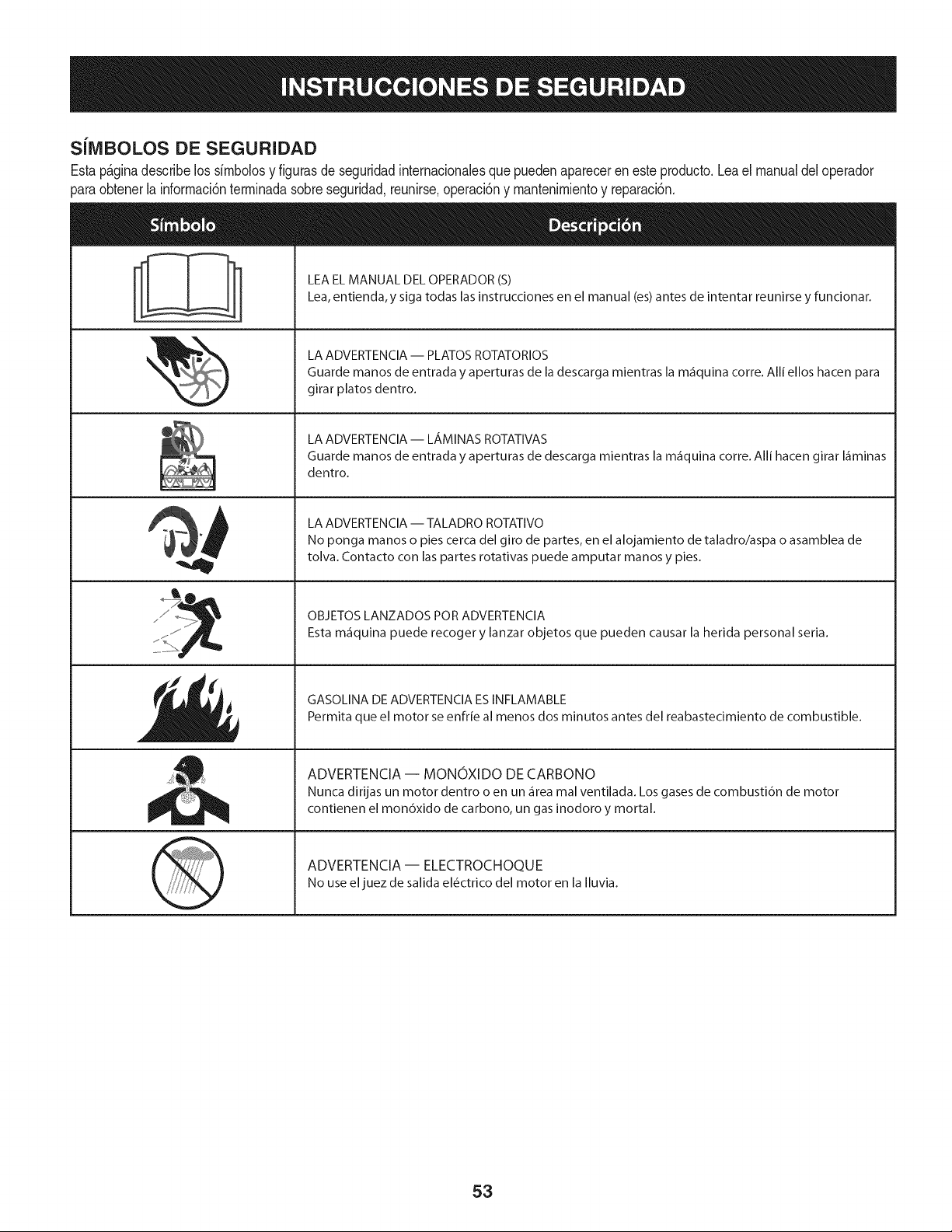
SilVIBOLOS DE SEGURIDAD
Estap_ginadescribe los simbolosy figurasde seguridadinternacionalesque puedenapareceren este producto.Lea el manualdeloperador
_araobtenerla informaci6nterminadasobreseguridad,reunirse,operaci6ny mantenimientoy reparaci6n.
&
LEA EL MANUAL DEL OPERADOR (S)
Lea, entienda,y siga todas las instrucciones en el manual (es) antes de intentar reunirse y funcionar.
LA ADVERTENCIA -- PLATOS ROTATORIOS
Guarde manos de entrada y aperturas de la descarga mientras la m_iquina corre. Alli ellos hacen para
girar platos dentro.
LA ADVERTENCIA -- LAMINAS ROTATIVAS
Guarde manos de entrada y aperturas de descarga mientras la m_iquina corre. Alli hacen girar I_iminas
dentro.
LA ADVERTENCIA -- TALADRO ROTATIVO
No ponga manos o pies cerca del giro de partes, en el alojamiento de taladro/aspa o asamblea de
tolva. Contacto con las partes rotativas puede amputar manos y pies.
OBJETOS LANZADOS POR ADVERTENClA
Esta m_iquina puede recoger y lanzar objetos que pueden causar la herida personal seria.
GASOLINA DE ADVERTENClA ESINFLAMABLE
Permita que el motor se enfrie al menos dos minutos antes del reabastecimiento de combustible.
ADVERTENCIA -- MONOXIDO DE CARBONO
Nunca dirijas un motor dentro o en un _irea mal ventilada. Los gases de combusti6n de motor
contienen el mon6xido de carbono, un gas inodoro y mortal.
ADVERTENCIA- ELECTROCHOQUE
No use el juez de salida el6ctrico del motor en la Iluvia.
53
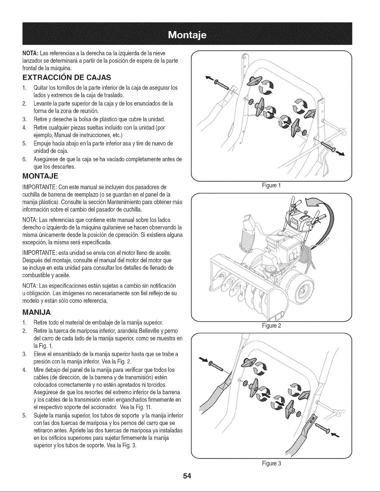
NOTA: Lasreferenciasa la derechaoa la izquierdade la nieve
lanzadorse deterrninar_,a partirde laposici6nde esperade la parte
frontalde la rn_.quina.
EXTRACCION DE CAJAS
1. QuitarlostorniNosde la parteinferiorde la caja deasegurarlos
ladosy extrernosdela cajade traslado.
2. Levantela partesuperiorde la caja y de los enunciadosde la
forrnade la zonade reuni6n.
3. Retirey desechela bolsade pl_.sticoque cubrela unidad.
4. Retirecualquierpiezassueltasincluidocon la unidad (por
ejernplo,Manualdeinstrucciones,etc.)
5. Ernpujehaciaabajoen la parteinferiorasa y tire de nuevode
unidaddecaja.
6. AsegOresedequela caja seha vaciadocornpletarnenteantesde
quelos descartes.
iVIONTAJE
IMPORTANTE:Conestemanualseincluyendos pasadoresde
cuchiNade barrenade reernplazo(o se guardanenel panelde la
rnanijapl_.stica).Consultela secci6nMantenirnientoparaobtenerrn_.s
inforrnaci6nsobreelcarnbiodel pasadorde cuchilla.
NOTA:Las referenciasque contieneestemanualsobrelos lados
derechoo izquierdode la rn_.quinaquitanievese hacenobservandola
rnisrnaOnicarnentedesdela posici6ndeoperaci6n.Siexistieraalguna
excepci6n,la rnisrnaser_.especificada.
IMPORTANTE:esta unidadse envfacon el motorIlenode aceite.
Despu_sdelrnontaje,consulteel manualdel motordelmotorque
se incluyeenestaunidadparaconsultarlos detallesde Nenadode
combustibley aceite.
NOTA:Lasespecificacionesest_.nsujetasacarnbiosin notificaci6n
uobligaci6n.Las imP.genesno necesariarnenteson fiel reflejode su
rnodeloy est_.ns61ocornoreferencia.
iVIANIJA
1. Retiretodoel materialdeernbalajede la rnanijasuperior.
2. Retirela tuercade rnariposainferior,arandelaBellevilley perno
delcarrode cadaladode larnanijasuperior,cornose rnuestraen
la Fig. 1.
3. Eleveel ensarnbladode la rnanijasuperiorhastaquese trabea
presi6ncon la rnanijainferior.Vea la Fig.2.
4. Miredebajodel panelde la rnanijaparaverificarquetodoslos
cables(dedirecci6n,de la barrenay detransrnisi6n)est_n
colocadoscorrectarnentey no est_napretadosni torcidos.
AsegOresede que los resortesdel extrernoinferiorde la barrena
y los cablesde la transrnisi6nest_nenganchadosfirrnernenteen
el respectivosoportedel accionador.Veala Fig.11.
5. Sujetela rnanijasuperior,los tubosde soporte y la rnanijainferior
con lasdos tuercasde rnariposay los pernosdelcarro quese
retiraronantes.Aprietelas dostuercasde rnariposaya instaladas
en losorificiossuperioresparasujetarfirrnernentela rnanija
superiory lostubos de soporte.Veala Fig.3.
f
f
/J
Figure1
Figure2
J
J
54
Figure3
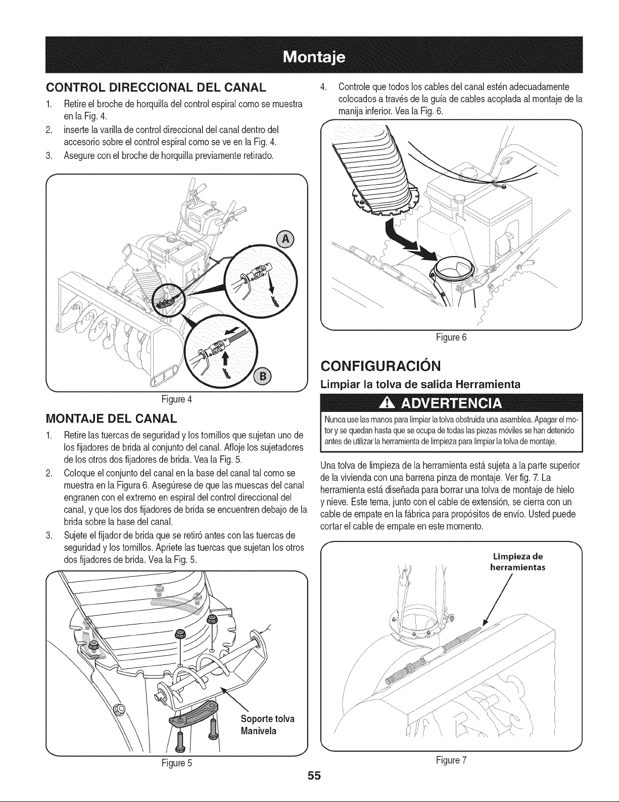
CONTROL DIRECCIONAL DEL CANAL
1, Retireel brochede horquilladel controlespiralcomose muestra
enla Fig. 4.
2. insertela varillade controldireccionaldel canal dentrodel
accesoriosobreel controlespiralcomo se veen la Fig.4.
3. Asegureconel brochede horquillapreviarnenteretirado.
\
Figure4
iVlONTAJE DEL CANAL
1. Retirelas tuercasde seguridady lostornillosque sujetanunode
los fijadoresde bridaal conjuntodel canal.Aflojelos sujetadores
delos otrosdosfijadoresdebrida. Veala Fig. 5.
2. Coloqueel conjuntodelcanal enla basedel canaltal como se
muestraen la Figura6. AsegQresede que las muescasdel canal
engranencon elextrernoen espiraldelcontroldireccionaldel
canal,y que losdos fijadoresde brida se encuentrendebajodela
bridasobrela basedel canal.
3. Sujeteel fijadordebridaquese retir6antescon las tuercasde
seguridady los tornillos.Aprietelas tuercasque sujetanlosotros
dosfijadoresde brida.Veala Fig.5.
.-,,,
Figure5
Soporte tolva
Manivela
4. Controlequetodosloscablesdel canalest_nadecuadamente
colocadosa travesde la guiadecablesacopladaal montajede la
rnanijainferior.Veala Fig.6.
/ /
ji
Figure6
CONFIGURACI6N
Limpiar la tolva de salida Herramienta
e A
Nuncauselasmanosparalimpiarlatolvaobstruidaunaasamblea.Apagarelmo-
tory sequedanhastaqueseocupadetodaslaspiezasm6vilessehandetenido
antesdeutilizarla herramientadelimpiezaparalimpiarlatolvademontaje.
Unatolvade limpiezade la herramientaest,.sujetaa la partesuperior
de la viviendacon unabarrenapinzade rnontaje.Vet fig. 7.La
herramientaest,.diseSadaparaborrarunatolvade montajede hielo
y nieve.Estetema,juntocon elcable deextensi6n,se cierracon un
cablede empateenla f_.bricapara prop6sitosde envio.Ustedpuede
cortarel cablede empateen este momento.
Limpieza de
herramientas
!
/
/
/'
/
Figure7
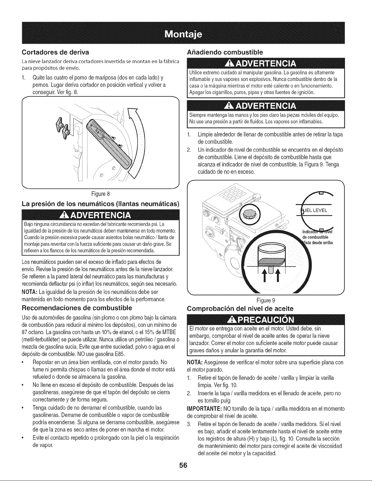
Cortadores de deriva
La nieve lanzador deriva cortadores invertida se montan en la f_fibrica
para prop6sitos de envio.
1. Ouitelascuatroelpornode rnariposa(dosen cadalado)y
pernos.Lugarderivacortadoren posici6nverticaly voivera
conseguir.Verfig.8.
f
A5adiendo combustible
Utiliceextremocuidadoal manipulargasolina.Lagasolinaesaltamente
inflamableysusvaporessonexplosivos.Nuncacombustibledentrodela
casao lam_quinamientraselmotorestecalienteoenfuncionamiento.
Apagarloscigarrillos,puros,pipasy otrasfuentesdeignici6n.
//
/ o
Figure8
La presi6n de los neumaticos (llantas neumaticas)
Bajoningunacircunstancianoexcedandelfabricanterecomiendapsi.La
igualdaddelapresi6ndelosneum_ticosdebenmantenerseentodomomento.
Cuandolapresi6nexcesivapuedecausarasientosbolasneum_tico/ Ilantade
montajeparareventarconlafuerzasuficienteparacausarundaSograve.Se
refierenalosflancosdelosneum_ticosdelapresi6nrecomendada.
Losneurn_ticospuedenser el excesode infladoparaefectosde
envio.Reviselapresi6ndelos neurn_ticosantesde la nievelanzador.
Serefierena la paredlateraldel neurn_ticoparalas rnanufacturasy
recorniendadeflactarpsi (o inflar)losneurn_ticos,segOnsea necesario.
NOTA:La igualdadde la presi6nde los neurn_ticosdebe set
rnantenidaen todornornentopara losefectosde laperformance.
Recomendaciones de combustible
Usodeautorn6vilesde gasolina(sinplornoo conplornobajo la c_rnara
de cornbusti6nparareduciral rninirnolos dep6sitos),conun rninirnode
87octano.Lagasolinaconhastaun 10%deetanol,o el 15%deMTBE
(rnetil-terbutil_ter)sepuedeutilizar.Nuncautiliceunpetr61eo/ gasolinao
rnezcladegasolinasucia.Evitequeentresuciedad,polvoo aguaen el
dep6sitode combustible.NOusegasolinaE85.
• Repostaren un _rea bien ventilada,con el motorparado.No
fumeni perrnitachispaso llamasenel _readondeel motorest_
refueledo donde se alrnacenala gasolina.
• NoIleneen excesoel dep6sitode combustible.Despu_sde las
gasolineras,asegOresede queeltap6ndel dep6sitosecierra
correctarnentey de forrnasegura.
• Tengacuidadode no derrarnarel combustible,cuandolas
gasolineras.Derrarnedecombustibleo vaporde combustible
podriaencenderse.Si alguna sederrarnacombustible,asegOrese
de que la zonaes secoantesdeponeren rnarchael motor.
• Eviteel contactorepetidoo prolongadocon la piel o la respiraci6n
de vapor.
Siempremantengalas manosy lospies clarolaspiezasm6vilesdel equipo.
Nouse unapresi6na partirde fluidos.Losvaporesson inflamables.
.
2.
Lirnpiealrededorde Ilenarde combustibleantesde retirarlatapa
de combustible.
Unindicadorde niveldecombustiblese encuentraenel dep6sito
de combustible.Lleneel dep6sitode combustiblehastaque
alcanzael indicadorde niveldecombustible,la Figura9. Tenga
cuidadode no en exceso.
sta desde arriba
J
Figure9
Comprobaci6n del nivel de aceite
Elmotorse entregacon aceiteen el motor.Usteddebe,sin
embargo,cornprobarel nivelde aceiteantesde operarla nieve
lanzador.Correrel motorconsuficienteaceite motorpuedecausar
gravesdaSosy anularlagarantiadel motor.
NOTA: AsegOresede verificarel motorsobreunasuperficieplanacon
el motorparado.
1. Retireel tap6nde Ilenadode aceite/ varillay lirnpiarla varilla
lirnpia.Verfig. 10.
2. Insertela tapa/ varillarnedidoraen el Ilenadode aceite,perono
es tornillopulg
IMPORTANTE:NOtornillode la tapa/ varillarnedidoraen el rnornento
de cornprobarel niveldeaceite.
3. Retireel tap6nde Ilenadodeaceite/ varillarnedidora.Siel nivel
es bajo,aSadirel aceite lentarnentehastael nivelde aceite entre
los registrosde altura(H) y bajo(L), fig. 10.Consultela secci6n
de rnantenirnientodel motorparacorregirelaceitedeviscosidad
del aceitedel motory la capacidad.
56
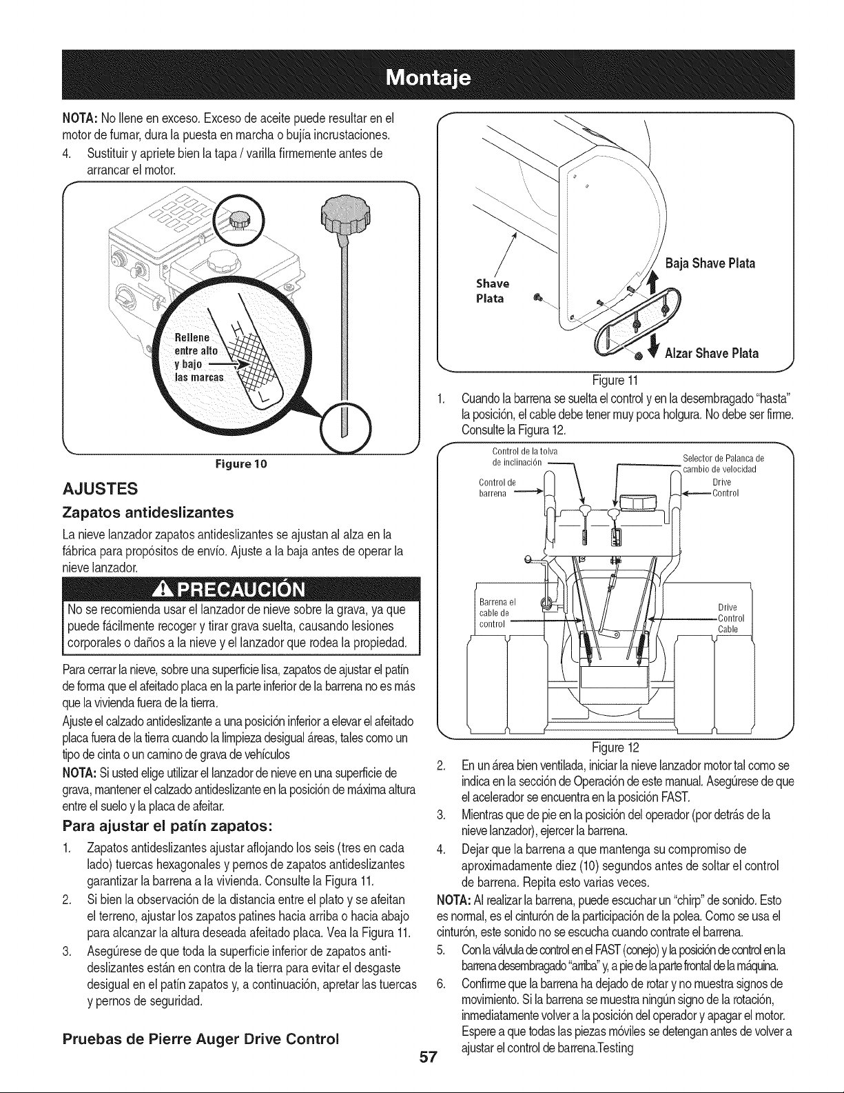
NOTA:No Ileneen exceso.Excesode aceite puederesultarenel
motordefumar,dura la puestaen marchao bujiaincrustaciones.
4. Sustituiry aprietebien la tapa / varillafirmementeantesde
arrancarel motor.
f
\
Figure 10
AJUSTES
Zapatos antideslizantes
La nievelanzadorzapatosantideslizantesse ajustanal alzaen la
f_.bricapara prop6sitosde envio.Ajustea la baja antesde operarla
nievelanzador.
No se recomiendausarellanzadorde nievesobrela grava,ya que
puedefMImente recogery tirargravasuelta,causandolesiones
corporaleso da_osa lanievey el lanzadorquerodeala propiedad.
Paracerrarlanieve,sobreunasuperficielisa,zapatosde ajustarelpatin
deformaqueelafeitadoplacaenlaparteinferiorde labarrenanoes m_.s
quelaviviendafueradelatierra.
Ajusteel calzadoantideslizantea unaposici6ninferioraeievarelafeitado
placafuerade la tierracuandolalimpiezadesigual_.reas,talescomoun
tipodecintao uncaminodegravadevehkulos
NOTA:Siustedeligeutilizarellanzadorde nieveen unasuperficiede
grava,mantenerel calzadoantidedizanteenlaposici6ndemaximaaltura
entreelsueloy laplacadeafeitar.
Para ajustar el patin zapatos:
1. Zapatosantideslizantesajustaraflojandolos seis (tresen cada
lado)tuercashexagonalesy pernosdezapatosantideslizantes
garantizarla barrenaa la vivienda.Consultela Figura11.
2. Si bienla observaci6nde la distanciaentreel platoy se afeitan
el terreno,ajustarlos zapatospatineshaciaarribao haciaabajo
paraalcanzarla alturadeseadaafeitadoplaca.Veala Figura11.
3. AsegQresede quetoda iasuperficieinferiordezapatosanti-
dedizantesest_.nencontradeia tierrapara evitarel desgaste
desigualenel patinzapatosy,a continuaci6n,apretarlas tuercas
y pernosdeseguridad.
Pruebas de Pierre Auger Drive Control
57
\
Baja Shave Plata
AlzarShave Plata
Figure11
1. Cuandolabarrenasesueltael controlyen ladesembragado"hasta"
laposici6n,el cabledebetenetmuypocaholgura.Nodebeset firme.
Consultela Figura12.
f Control de latolva
_° _rtdrer_indc:_ _--_ /_ _°SelecbiLrdi_e,iiiall 'ndcadde
Figure12
2. Enunareabienventilada,iniciarla nievelanzadormotortalcomose
indicaenlasecci6ndeOperaci6nde estemanual.AsegQresedeque
elaceleradorseencuentraenlaposici6nFAST.
3. Mientrasquedepieenlaposici6ndeloperador(potdetr_.sde la
nievelanzador),ejercerla barrena.
4. Dejarquela barrenaa quemantengasucompromisode
aproximadamentediez (10)segundosantesde soltarel control
de barrena.Repitaesto variasveces.
NOTA:AI realizarla barrena,puedeescucharun"chirp"desonido.Esto
es normal,eselcintur6nde la participaci6nde lapolea.Comoseusael
cintur6n,estesonidono seescuchacuandocontrateel barrena.
5. Conlav_.lvuladecontrolenelFAST(conejo)y laposici6ndecontrolen la
barrenadesembragado"arriba"y,a piedela partefrontaldelam_.quina.
6. Confirmequelabarrenahadejadode rotarynomuestrasignosde
movimiento.Si la barrenasemuestraningQnsignode la rotaci6n,
inmediatamentevoivera laposici6ndeloperadory apagarelmotor.
Esperea quetodaslas piezasm6vilessedetenganantesde volvera
ajustarelcontroldebarrena.Testing
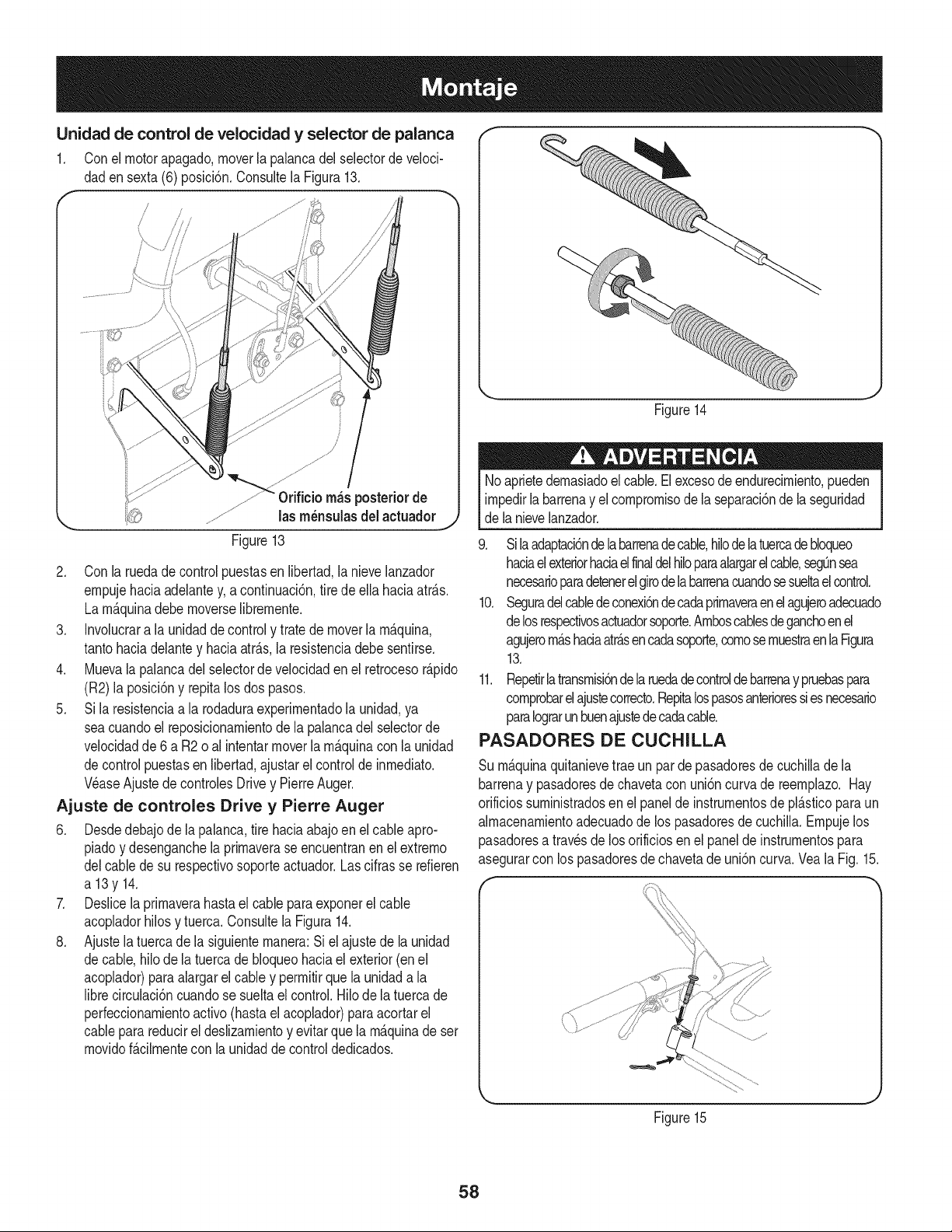
Unidadde controldevelocidady selector de palanca
1. Conel motorapagado,moverla palancadel selectorde velocio
dadensexta (6)posici6n.Consultela Figura13.
f
J /
\
f'++..........
0rifieio rn_s posteriorde
las rn_nsulasdel actuador
Figure13
J
2. Con la ruedade controlpuestasen lbertad, la nievelanzador
ernpujehaciaadelantey, a continuaci6n,tire de ella haciaatr_.s.
La rn_.quinadebe rnoverselbrernente.
3. Involucrara la unidaddecontroly tratede moverla rn_.quina,
tantohaciadelantey haciaatr_.s,la resistenciadebesentirse.
4. Muevala palancadelselectorde velocidaden el retrocesor_.pido
(R2) la posici6ny repitalosdos pasos.
5. Si laresistenciaa la rodaduraexperirnentadola unidad,ya
seacuandoel reposicionarnientode la palancadel selectorde
velocidadde6 a R2o al intentarmoverla rn_.quinacon launidad
decontrolpuestasenlibertad,ajustarel controlde inrnediato.
Wase Ajustede controlesDrivey PierreAuger.
Ajuste de controles Drive y Pierre Auger
6. Desdedebajode lapalanca,tire haciaabajoen el cable apro-
piadoy desenganchela prirnaverase encuentranen el extrerno
delcablede su respectivosoporteactuador.Lascifrasse refieren
a13y14.
7. Deslicela prirnaverahastael cableparaexponerel cable
acopladorhilosy tuerca.Consultela Figura14.
8. Ajustela tuercade lasiguienternanera:Si el ajustede la unidad
decable,hlo de la tuercade bloqueohaciael exterior(en el
acoplador)paraalargarelcable y perrnitirquela unidada la
librecirculaci6ncuandose sueltael control.Hilo de la tuercade
perfeccionarnientoactivo(hastael acoplador)paraacortarel
cablepara reducirel deslizarnientoy evitarque la rn_.quinade ser
rnovidof_.cilrnentecon la unidadde controldedicados.
f
Figure14
Noaprietedernasiadoel cable.El excesode endurecirniento,pueden
irnpedirla barrenay el cornprornisodela separaci6nde laseguridad
de la nievelanzador.
9. Si laadaptaci6ndelabarrenadecable,hlodelatuercade bloqueo
haciaelexteriorhaciael finaldelhlo paraalargarel cable,segQnsea
necesarioparadetenerel girodela barrenacuandosesueltael control.
10. Seguradelcabledeconexi6ndecadaprirnaveraenelagujeroadecuado
delosrespectivosactuadorsoporte.Arnboscablesdeganchoenel
agujerorn_.shaciaatr_.sencadasoporte,cornosernuestraenlaFigura
13.
11. Repetirlatransrnisi6ndelaruedadecontrolde barrenay pruebaspara
cornprobarelajustecorrecto.Repitalospasosanterioressiesnecesario
paraIograrunbuenajustedecadacable.
PASADORES DE CUCHILLA
Su rn_.quinaquitanievetrae unparde pasadoresde cuchila de la
barrenay pasadoresde chavetacon uni6ncurvade reernplazo. Hay
orificiossurninistradosen el paneldeinstrurnentosdepl_.sticoparaun
alrnacenarnientoadecuadodelos pasadoresde cuchila. Ernpujelos
pasadoresa travesde los orificiosen el panelde instrurnentospara
asegurarcon los pasadoresde chavetade uni6ncurva.Vea la Fig.15.
Figure15
58
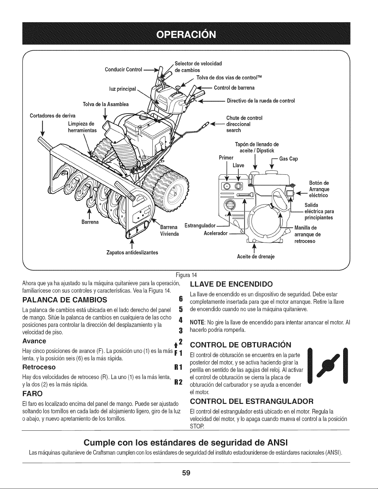
f
Conducir Control
velocidad
de cambios
Tolvade dos vias de controlTM
luz principal
Tolvade la Asamblea
Cortadores de deriva
Limpieza de
herramientas
f
Barrena
\Barrena
Vivienda
Zapatos antideslizantes
Control de barrena
-,_ Directivo de la rueda de control
Chute de control
direccional
search
Tap6nde Ilenadode
aceite/ Dipstick
Primer | r-- GasCap
/,,ovo
Salida
['_._ _---_l-_ _ ', .) prmclplantes
Aceitede drenaje
Ahoraqueya haajustadosu la rn_.quinaquitanieveparala operaci6n,
farniliaricesecon sus controlesy caracteristicas.Veala Figura14.
PALANCA DE CAMBIOS
La palancade carnbiosest,. ubicadaen el ladoderechodel panel
de mango.SitQela palancade carnbiosencualquieradelas ocho
posicionesparacontrolarladirecci6ndeldesplazarnientoy la
velocidadde piso. 3
Avarice t 2
Haycincoposicionesdeavance(F). La posici6nuno(1)es la rn&sF 1
lenta,y la posici6nseis(6) es la rn_.sr_.pida.
Retroceso R 1
Haydosvelocidadesde retroceso(R). Launo(1)es la rn_.slenta,
y la dos (2)es la rn_.sr_.pida. R2
FARO
.J
Figura14
LLAVE DE ENCENDIDO
LaIlavedeencendidoes undispositivode seguridad.Debeestar
6 cornpletarnenteinsertadaparaqueel motorarranque.Retirela Ilave
5 de encendidocuandono usela rn_.quinaquitanieve.
4
NOTE: Nogirela Ilavede encendidopara intentararrancarel motor.AI
hacerlopodria rornperla.
CONTROL DE OBTURACION
Elcontroldeobturaci6nse encuentraen la parte
posteriordelmotor,y seactiva haciendogirar la
perillaensentidode lasagujasdel reloj.AI activar
el controlde obturaci6nse cierrala placade
obturaci6ndel carburadory se ayudaa encender
el motor.
Elfaro es Iocalizadoencirnadelpaneldemango.Puedeser ajustado
soltandolostornillosen cadaladodelalojarnientoligero,girode la luz
oabajo,y nuevoapretarnientode los tornillos.
CONTROL DEL ESTRANGULADOR
Elcontroldelestranguladorest,.ubicadoen el motor.Regulala
velocidaddelmotor,y Ioapagacuandornuevael controla la posici6n
STOR
Cumple con los estandares de seguridad de ANSI
Lasrn&quinasquitanievede Craftsmancurnplenconlosest&ndaresde seguridaddel institutoestadounidensedeest&ndaresnacionales(ANSI).
59
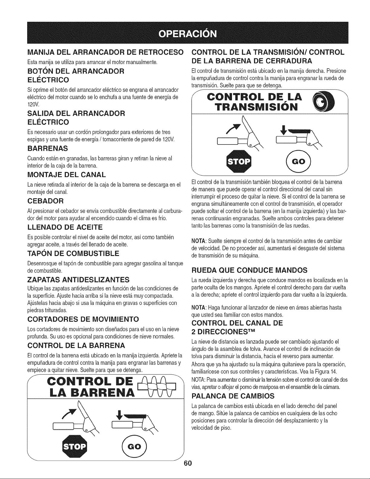
MANIJA DEL ARRANCADOR DE RETROCESO
Estarnanijase utilizaparaarrancarel motorrnanualrnente.
BOTON DEL ARRANCADOR
ELECTRICO
Sioprirneel bot6ndel arrancadorel_ctricose engranael arrancador
el_ctricodel motorcuandose Ioenchufaa unafuentedeenergiade
120V.
SALIDA DEL ARRANCADOR
ELI_CTRICO
Es necesariousar uncord6nprolongadorparaexterioresde tres
espigasy unafuentede energia/ tornacorrientede paredde 120V.
BARRENAS
Cuandoest_.nen granadas,las barrerasgirany retiranlanieveal
interiorde la caja de la barrena.
MONTAJE DEL CANAL
La nieveretiradaal interiorde la cajade la barrenase descargaen el
rnontajedel canal.
CEBADOR
AI presionarel cebadorse enviacombustibledirectarnentealcarbura-
dordelmotorparaayudaral encendidocuandoel clirnaes frio.
LLENADO DE ACEITE
CONTROL DE LA TRANSMISION/CONTROL
DE LA BARRENA DE CERRADURA
Elcontroldetransrnisi6nest,.ubicadoen la rnanijaderecha.Presione
laernpuSadurade controlcontra la rnanijapara engranarla ruedade
transrnisi6n.Suelteparaquese detenga.
CONTROL DE LA
TRANSiVI|S|ON
Elcontrolde la transrnisi6ntarnbi_nbloqueael controlde la barrena
de rnaneraque puedeoperar el controldireccionaldel canalsin
interrurnpirel procesode quitarla nieve.Siel controlde la barrenase
engranasirnult_.nearnentecon el control de transrnisi6n,el operador
puedesoltarel controlde labarrena(enla rnanijaizquierda)y lasbar-
renascontinuar_.nengranadas.Sueltearnboscontrolesparadetener
tantolas barrenascornola transrnisi6nde las ruedas.
Es posiblecontrolarel nivelde aceitedel motor,asi cornotarnbi_n
agregaraceite,a travesdel Ilenadode aceite.
TAPON DE COMBUSTIBLE
Desenrosqueel tap6ndecombustiblepara agregargasolinaal tanque
decombustible.
ZAPATAS ANTI DES LIZANTES
Ubiquelas zapatasantideslizantesen funci6nde lascondicionesde
la superficie.Ajustehaciaarriba si la nieveest,.rnuycornpactada.
AjQstelashaciaabajosi usala rn_.quinaengravaso superficiescon
piedrastrituradas.
CORTADORES DE MOVlMIENTO
Loscortadoresde rnovirnientosondiseSadosparael usoen la nieve
profunda.Su usoes opcionalpara condicionesde nievenorrnales.
CONTROL DE LA BARRENA
Elcontrolde la barrenaest,.ubicadoenla rnanijaizquierda.Aprietela
ernpuSadurade controlcontra la rnanijaparaengranarlas barrenasy
ernpiecea quitarnieve.Sueltepara quese detenga.
J CONTROL DiE
LA BARRENA
NOTA:Sueltesiernpreel controlde latransrnisi6nantesde carnbiar
de velocidad.Deno procederasi, aurnentar_,eldesgastedel sisterna
de transrnisi6nde su rn_.quina.
RUEDA QUECONDUCE MANDOS
Laruedaizquierday derechaqueconducernandoses Iocalizadaen la
parteocultade los mangos.Aprieteel control derechoparadar vuelta
a la derecha;aprieteel controlizquierdoparadarvueltaa la izquierda.
NOTA:Hagafuncionaral lanzadorde nieveen _.reasabiertashasta
que ustedseafamiliarcon estosrnandos.
CONTROL DEL CANAL DE
2 DIRECCIONES TM
Lanievede distanciaes lanzadapuedesercarnbiadoajustandoel
_.ngulode la asarnbleade tolva.Avanceel controldeinclinaci6nde
tolvaparadisrninuirla distancia,haciael reversoparaaurnentar.
Ahoraqueya haajustadosu larn_.quinaquitanievepara la operaci6n,
farniliaricesecon suscontrolesy caracteristicas.Veala Figura14.
NOTA:Paraaurnentarodisrninuirla tensi6nsobreelcontrolde canalde dos
vias,apretaro aflojarelpornode rnariposaen elensarnbledelac_.rnara.
PALANCA DE CAMBIOS
Lapalancade carnbiosest,. ubicadaen el ladoderechodel panel
de mango.SitQela palancadecarnbiosen cualquierade las ocho
posicionesparacontrolarla direcci6ndel desplazarnientoy la
velocidaddepiso.
6O
Avarice
Haycincoposicionesde avance(F). Laposici6nuno(1)es larn_.s
lenta,y la posici6nseis(6)es larn_.sr_.pida.
Retroceso
Haydosvelocidadesde retroceso(R). Launo(1)es la rn_.slenta,y la
dos (2)es larn_.sr_.pida.
FARO
El faroes Iocalizadoencirnadel panelde mango.Puedeset ajustado
soltandolos tornillosen cadalado del alojarnientoligero,giro de la luz
o abajo,y nuevoapretarnientode los tornillos.
LLAVE DE ENCENDIDO
La Ilavede encendidoes un dispositivode seguridad.Debeestar
cornpletarnenteinsertadaparaqueel motorarranque.Retirela Ilave
de encendidocuandono use la rn_.quinaquitanieve.
NOTE:No girela Ilavede encendidoparaintentararrancarel motor.AI
hacerlopodrfarornperla.
CONTROL DE OBTURACION
El controlde obturaci6nse encuentraen la parteposteriordel motor,
y seactiva haciendogirar la perillaen sentidode las agujasdel reloj.
AI activarel controlde obturaci6nsecierra la placade obturaci6ndel
carburadory se ayudaa encenderel motor.
CONTROL DEL ESTRANGULADOR
El controldel estranguladorest,.ubicadoen el motor.Regulala
velocidaddel motor,y Io apagacuandornuevael controla la posici6n
STOR
MANIJA DEL ARRANCADOR DE RETRO-
CESO
Estarnanijase utilizaparaarrancarel motorrnanualrnente.
BOTON DEL ARRANCADOR
ELECTRICO
Si oprirneel bot6ndelarrancadorel_ctricose engranael arrancador
el_ctricodel motorcuandose Ioenchufaa unafuentedeenergiade
120V.
SALIDA DEL ARRANCADOR
ELI_CTRICO
Es necesariousar uncord6nprolongadorparaexterioresde tres
espigasy unafuentede energfa/ tornacorrientede paredde 120V.
BARRENAS
Cuandoest_.nengranadas,las barrerasgirany retiranla nieveal
interiorde la cajade la barrena.
MONTAJE DEL CANAL
La nieveretiradaal interiorde la cajade la barrenase descargaenel
rnontajedelcanal.
CEBADOR
AI presionarel cebadorse enviacombustibledirectamenteal carbura-
dordel motorpara ayudaral encendidocuandoel climaes frio.
LLENADO DE ACEITE
Es posiblecontrolarel nivelde aceitedel motor,asi comotambi@n
agregaraceite,a travesdel Ilenadode aceite.
TAPON DE COMBUSTIBLE
Desenrosqueel tap6ndecombustiblepara agregargasolinaal tanque
de combustible.
ZAPATAS ANTIDESLIZANTES
Ubiquelas zapatasantideslizantesen funci6n de las condicionesde
la superficie.Ajustehaciaarribasi la nieveest,. rnuycornpactada.
AjQstelashaciaabajosi usa la rn_.quinaen gravaso superficiescon
piedrastrituradas.
CORTADORES DE MOVlMIENTO
Loscortadoresde rnovirnientosondise_adospara el usoen la nieve
profunda.Su uso es opcionalparacondicionesde nievenorrnales.
CONTROL DIRECCIONAL DEL CANAL
Lacontroldireccionaldel canales Iocalizadaen el ladoizquierdodel
lanzadordenieve.
• Paracarnbiarladirecci6nhaciala cual searrojala nieve,gire
en sentidode lasagujasdel relojpara descargarla nievehacia
la izquierda,y endirecci6ncontrariade las agujasdel relojpara
descargarlahaciala derecha.
HERRAMIENTA DE LIMPIEZA
Laherrarnientadelirnpiezadel canalest,. ajustadaconvenienternente
a la parte posteriorde la cajade la barrenacon un pasadordeensarn-
blado.Si se acurnulannievey hielo en el canaldedescargadurante
laoperaci6n,procedacornose indicaa continuaci6nparalirnpiarde
rnanerasegurael rnontajedel canaly la aberturadel canal:
Nuncausesus rnanosparaliberarun rnontajede canaltapado.Antes
de destaparlo,apagueel motory perrnanezcadetr_.sde lasrnanijas
hastaquetodaslaspartes rn6vilesse hayandetenido.
1. Suelteel controlde la barrenay el controlde latransrnisi6n.
2. Paradetenerel motorsaquela Ilavede encendido.
3. Saquelaherrarnientadelirnpiezadelpasadorque laajustaa la
parteposteriorde lacaja de labarrena.
4. Useel extrernocon forrnade paladela herrarnientade lirnpieza
paradesplazary recogerlanievey el hielo que seforrnaroncerca
del conjuntodel canal.
5. Vuelvaa ajustarla herrarnientadelirnpiezaal pasadordeens-
arnbladoubicadoen la parteposteriorde lacajade la barrena,
insertede nuevola Ilavede encendidoy enciendael motorde la
rn_.quinaquitanieve.
6. Paradoen la posici6ndeloperador(detr_.sde la rn_.quinaquita-
nieve),engraneelcontroldelabarrenaduranteunossegundospara
elirninarlanieveoelhieloquehayanquedadoenelconjuntodel
canal.
61
ANTES DE ENCENDER EL MOTOR
Lea,cornprenday siga todaslas instruccionesy advertenciasque
aparecenen la rn_quinayen estemanualantesde operarla.
Aceite
Elmotorse envi6conaceiteen el motor.Controleel nivelde aceite
antesde cadaoperaci6nparaasegurarsede quehayaaceite
suficienteen el motor.Paraobtenerrn_sinstrucciones,rernitasea los
pasosqueaparecenen la p_gina53.
1. Saquela varilladel nivelde aceitedelorificiodeIlenadode
aceite.
2. Controley cornpruebeque el niveldeaceiteest_ hastaarribaen
la rnarcaCHOKEde la varilladelniveldelaceite.
3. Si el nivelde aceite no IlegahastaCHOKE,viertaaceitede
motornuevo(5W-30,conuna clasificaci6nminimade SLiSJ)
lentarnentea trav_sde la abertura.Vuelvaa colocarlavarilladel
nivelaceite en el Ilenadodeaceitey controlenuevarnenteel nivel
deaceite.
Gasolina
Tengaextrernocuidadocuandornanipulegasolina.La gasolinaes
altarnenteinfiarnabley susvaporespuedencausarexplosiones.
Nuncaagreguecombustiblea la rn_quinaen interioreso rnientras
el motorest,. calienteo en funcionarniento.Apaguelos cigarrillos,
cigarros,pipasy otrasfuentesde cornbusti6n.
• Alrnacenela gasolinaen unrecipienteaprobadolirnpioy coloque
la tapaen el recipiente.
• AsegOresede queel recipientedesdeelcualviertelagasolina
est_lirnpioy noest_oxidadonicontarninadoconotrasparficulas
extra,as.
NOTA:Dentrode la aperturaparaIlenadodecombustiblepuede
encontrarseunatapa guardapolvosde pl_stico.Retirey descarte,si la
hubiera.
• Llenesiernpreel tanquede combustibleal aire libre y useun
ernbudoo pico paraevitar derrarnarnientos.
• Lleneeltanquedecombustiblecongasolinasinplorno,lirnpiay fresca.
• NuncaIlenecornpletarnenteeltanque.Lleneeltanquehasta1/2pulgpor
debajodeltope,dejandoasiespacioparaladilataci6ndelcombustible.
• AsegOresede lirnpiarel combustibleque sehayaderrarnado
antesde arrancarel motor.
ENCENDIDO DEL MOTOR
1. Conecteel cablede labujiaa la rnisrna.Cornpruebequeel lazo
de metaldel extrernode la bujiaest_bienajustado(dentrode la
rnangade gorna)sobrela puntarnetAlicadela bujia.
2. AsegQresedequeel controlde la barrenay el controlde la
transrnisi6nest_nen posici6ndesengranada(sin presionar).
3. Insertela Ilavede encendidoen la ranura.AsegOresede que
entrea presi6nen su lugar.Nointentegirar la llave.
NOTA: Elmotorno puedearrancarsi la Ilaveno est_ cornpletarnente
insertadaen el interruptorde encendido.
Arrancador el_ctrico
Elarrancadorel_ctricoopcionalest&equipadocon un cablede ali-
rnentaci6ny un enchufede tresterrninalesconectadosa tierray est_
dise_adoparaoperarcon corrientedorn_sticade 120voltios. Debe
set utilizadoconun recept_culodetresterrninalescorrectarnente
conectadoa tierraen todo mornentoparaevitar la posibilidadde
descargasel_ctricas.Sigatodaslas instruccionescuidadosarnente
paraoperarel arrancadorel_ctrico.
Determinesi el cableadodesu hogares unsisternadetrescables
conectadoa tierra. Consultecon un electricistarnatriculadosi noest_
seguro.
Sicuentacon un recept_culode tres terrninales,sigalos siguientes
pasos:
1. Conecteel prolongadora la salidasituadaen la superficiedel
motor.Conecteel otroextrernodel prolongadoren unrecept_culo
deCA conconexi6natierrade tresterrninalesde 120voltios,en
un_reabienventilada.
2. Gireel controlde obturaci6na posici6nde obturaci6nCHOKE
I,"l (paraencendidoconelmotorenfrio).
NOTA:si el motorya est_caliente,ubiqueel controldel obturadoren
posici6nRUNen lugar de CHOKE IJl '
3. Presioneelcebadordoso tres vecespara arrancarel motoren
frio,asegur_ndosedecubrirel orificiode ventilaci6nsituadoen
el centrodel cebadorcuandoest_ presionando.
NOTA:NO UTILICEel cebadorpara reiniciarun motorcalientetras
unadetenci6nbreve.
4. Presioneel bot6ndel arrancadorparaarrancarel motor.
Paraprolongarla vidade arranque,el uso decornenzarlos ciclosa
corto (5 segundoscornorn_xirno,a continuaci6n,espereunrninuto).
.
6.
Unavez encendidoel motor,suelteel bot6ndel arrancador.
Mientrasse calientael motor,girelentarnenteel controldel obtu
radora posici6nRUN(apagado).Si el motorfalla,vuelvaa girar
r_pidarnenteel obturadora posici6nCHOKE IJl Y luego,
lentarnente,a posici6nRUNde nuevo.
7. Cuandodesconecteel prolongador,desenchufesiernpreel
extrernodelrecept_culode tres terrninalesen el tornacorriente
de paredantesde desenchufarelextrernoopuestode la
rn_.quinaquitanieve.
Arrancador de retroceso
1. Gireel controlde obturaci6na posici6nde obturaci6nCHOKE
I,._1 (encendidocon el motoren frio).
NOTA:Isi el motorya est&caliente,ubiqueel controldelobturadoren
posici6nRUNen lugar de CHOKE I,.=('1.
2. Presioneelcebadordoso tres vecespara arrancarel motoren
frio,asegur&ndosede cubrirel orificiode ventilaci6nsituadoen
el centrodel cebadorcuandoest_ presionando.
62
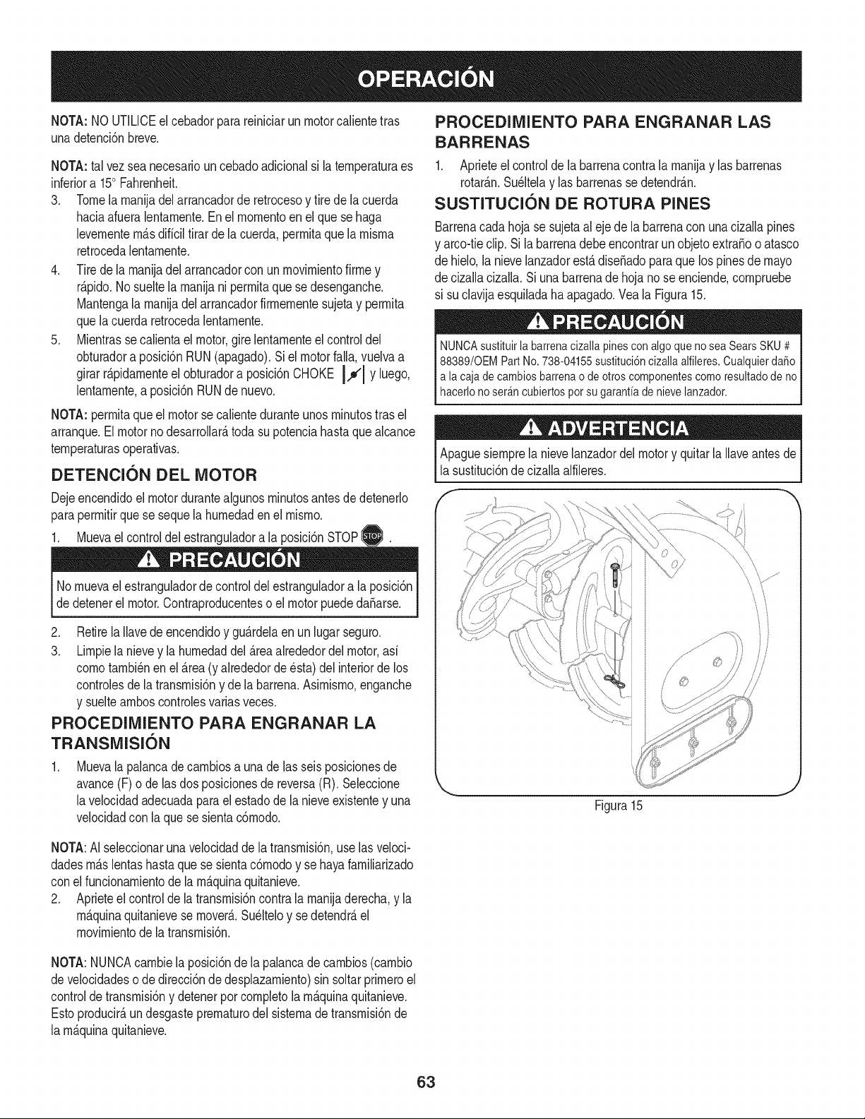
NOTA: NOUTILICEel cebadorparareiniciarun motorcalientetras
unadetenci6nbreve,
NOTA:tal vezsea necesariouncebadoadicionalsi la ternperaturaes
inferiora 150Fahrenheit.
3. Tomela rnanijadel arrancadorde retrocesoy tire de la cuerda
haciaafueralentarnente.Enel rnornentoen elque se haga
levernentern_.sdificiltirarde lacuerda,perrnitaque la rnisrna
retrocedalentarnente.
4. Tirede la rnanijadel arrancadorcon un rnovirnientofirrney
r@ido. Nosuelte la rnanijani perrnitaque sedesenganche.
Mantengala rnanijadel arrancadorfirrnernentesujetay perrnita
quelacuerda retrocedalentarnente.
5. Mientrasse calientael motor,gire lentarnenteel controldel
obturadora posici6n RUN(apagado).Si el motorfall& vuelvaa
girarr@idarnenteel obturadora posici6nCHOKE JJl Y luego,
lentarnente,a posici6nRUNdenuevo.
NOTA:perrnitaque el motorse calienteduranteunosrninutostrasel
arranque.Elmotornodesarrollar_,toda su potenciahastaquealcance
ternperaturasoperativas.
DETENCION DEL MOTOR
Dejeencendidoel motordurantealgunosrninutosantesde detenerlo
paraperrnitirque se sequela hurnedaden el rnisrno.
1. Muevael controldel estranguladora laposici6nSTOPi_.
®
No rnuevael estranguladordecontroldel estranguladora la posici6n
dedetenerel motor.Contraproducenteso el motorpuededaSarse.
2. Retirela Ilavedeencendidoy gu_.rdelaen un lugarseguro.
3. Lirnpiela nievey lahurnedaddel_.reaalrededordel motor,asi
cornotarnbi_nen el _.rea(y alrededorde _sta)delinteriorde los
controlesdela transrnisi6ny de la barrena.Asirnisrno,enganche
y sueltearnboscontrolesvariasveces.
PROCEDIMIENTO PARA ENGRANAR LA
TRANSMISION
Muevala palancade carnbiosa unade las seisposicionesde
avance(F) ode las dos posicionesde reversa(R). Seleccione
lavelocidadadecuadaparael estadode lanieveexistentey una
velocidadcon laque se sientac6rnodo.
PROCEDIMIENTO PARA ENGRANAR LAS
BARRENAS
1. Aprieteel control de la barrenacontrala rnanijay las barrenas
rotar_.n.Su@elay las barrenasse detendr_.n.
SLISTITLICION DE ROTURA PINES
Barrenacadahoja se sujetaal eje de la barrenacon una cizallapines
y arco-tieclip.Si la barrenadebeencontrarun objetoextraBooatasco
de hielo,la nievelanzadorest,.dise_adoparaquelos pinesde mayo
de cizallacizalla.Si unabarrenade hojanose enciende,cornpruebe
si suclavija esquiladaha apagado.Vea la Figura15.
NUNCAsustituirla barrenacizallapinesconalgoquenoseaSearsSKU# j
88389/0EMPartNo.738-04155sustituci6ncizallaalfileres.Cualquierda_o
a lacajadecambiosbarrenaodeotroscomponentescomoresultadodeno
haceronoser_ncubertospotsugaranta den eve anzador, j
Apaguesiernprela nievelanzadordel motory quitarla Ilaveantesde
la sustituci6nde cizallaalfileres.
\
Figura15
NOTA:AI seleccionarunavelocidaddela transrnisi6n,uselas veloci-
dadesrn_.slentashastaque se sientac6rnodoy se hayafarniliarizado
conel funcionarnientodela rn_.quinaquitanieve.
2. Aprieteel controlde latransrnisi6ncontrala rnanijaderecha,y la
rn_.quinaquitanievese mover&Su@eloy se detendr_,el
rnovirnientode latransrnisi6n.
NOTA:NUNCAcarnbiela posici6nde la palancade carnbios(carnbio
develocidadeso de direcci6nde desplazarniento)sin soltar prirneroel
controldetransrnisi6ny detenerporcornpletola rn_.quinaquitanieve.
Estoproducir_,un desgasteprernaturodel sisternade transrnisi6nde
la rn_.quinaquitanieve.
63
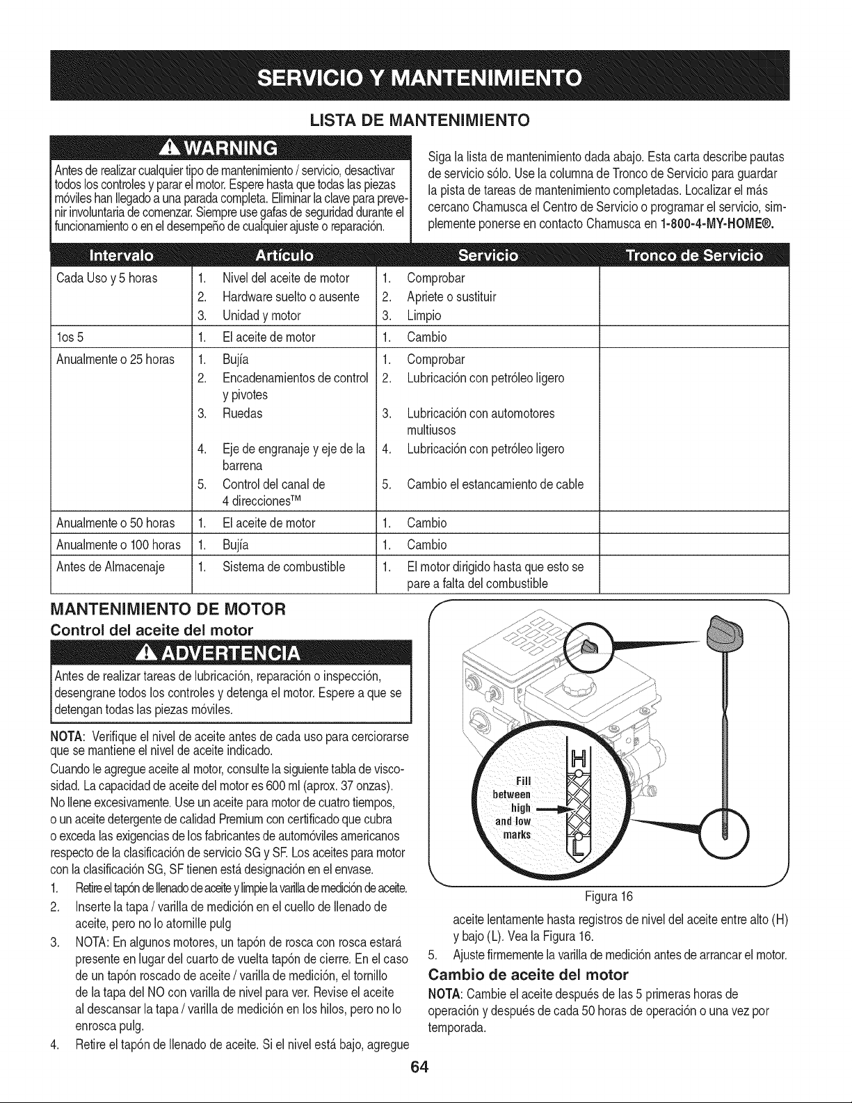
LISTA DE iVlANTENIIVllENTO
Antesderealizarcualquiertipode rnantenirniento/ servicio,desactivar
todosloscontrolesy pararel motor.Esperehastaque todaslaspiezas
rn6vilesbanIlegadoa unaparadacornpleta.Elirninarla claveparapreve-
nirinvoluntariade cornenzar.Siernpreusegalasdeseguridadduranteel
funcionarnientoo enel desernpeSodecualquierajusteo reparaci6n.
Sigala lista de rnantenirnientodadaabajo.Estacartadescribepautas
de servicios61o.Usela colurnnade Troncode Servicioparaguardar
la pista de tareasde rnantenirnientocornpletadas.Localizarel rn_.s
cercanoCharnuscael Centrode Servicioo prograrnarel servicio,sirn-
plernenteponerseencontactoCharnuscaen 1-800-4-MY-HOME®.
5. Carnbioel estancarnientode cable
1. Niveldel aceitede motor 1. Cornprobar
2. Hardwaresueltooausente 2. Aprieteosustituir
3. Unidadymotor 3. Lirnpio
1. El aceitede motor 1. Carnbio
1. Bujfa 1. Cornprobar
2. Encadenarnientosde control 2. Lubricaci6nconpetr61eoligero
y pivotes
3. Ruedas 3. Lubricaci6nconautornotores
rnultiusos
4. Ejede engranajeyejedela 4. Lubricaci6ncon petr61eoligero
barrena
5. Controldel canalde
4 direccionesTM
1. El aceitede motor 1.
1. Bujia 1.
1. Sisternade combustible 1.
CadaUso y 5 horas
los 5
Anualrnenteo 25 horas
Anualrnenteo 50 horas Carnbio
Anualrnenteo 100horas Carnbio
Antesde Alrnacenaje Elmotordirigidohastaqueestose
parea falta del combustible
iVlANTENIMIENTO DE MOTOR
Control del aceite del motor
Antesde realizartareasde lubricaci6n,reparaci6no inspecci6n,
desengranetodosloscontrolesy detengael motor.Esperea quese
detengantodaslas piezasrn6viles.
NOTA: Verifiqueel nivelde aceite antesde cadauso paracerciorarse
quese rnantieneel nivelde aceite indicado.
Cuandole agregueaceiteal motor,consultela siguientetablade visco-
sidad.Lacapacidaddeaceitedel motores 600rnl(aprox.37 onzas).
NoIleneexcesivarnente.Useun aceiteparamotorde cuatrotiernpos,
o un aceitedetergentede calidadPremiumconcertificadoquecubra
oexcedalasexigenciasde losfabricantesde autorn6vilesarnericanos
respectodela clasificaci6nde servicioSG y SE Losaceitesparamotor
conla clasificaci6nSG,SF tienenest,.designaci6nenelenvase.
1. Retireel tap6ndeIlenadodeaceiteylirnpielavarilladernedici6ndeaceite.
2. Insertela tapa/ varillade rnedici6nen el cuellode Ilenadode
aceite,perono Ioatornillepulg
3. NOTA:En algunosrnotores,un tap6nde roscacon roscaestate.
presenteen lugardel cuarto de vuelta tap6ndecierre.Enelcaso
de un tap6nroscadode aceite/ varilladernedici6n,el tornillo
de la tapadel NOcon varillade nivelparaver. Reviseel aceite
aldescansarla tapa/ varillade rnedici6nen los hilos,perono Io
enroscapulg.
4. Retireel tap6ndeIlenadode aceite.Si el nivelest,. bajo,agregue
Figura16
aceitelentarnentehastaregistrosde niveldel aceiteentre alto(H)
y bajo(L).Vea la Figura16.
5. Ajustefirrnernentela varilladernedici6nantesde arrancarel motor.
Cambio de aceite del motor
NOTA:Carnbieel aceite despu_sde las5 prirnerashorasde
operaci6ny despu_sdecada 50horasde operaci6no una vez por
ternporada.
64
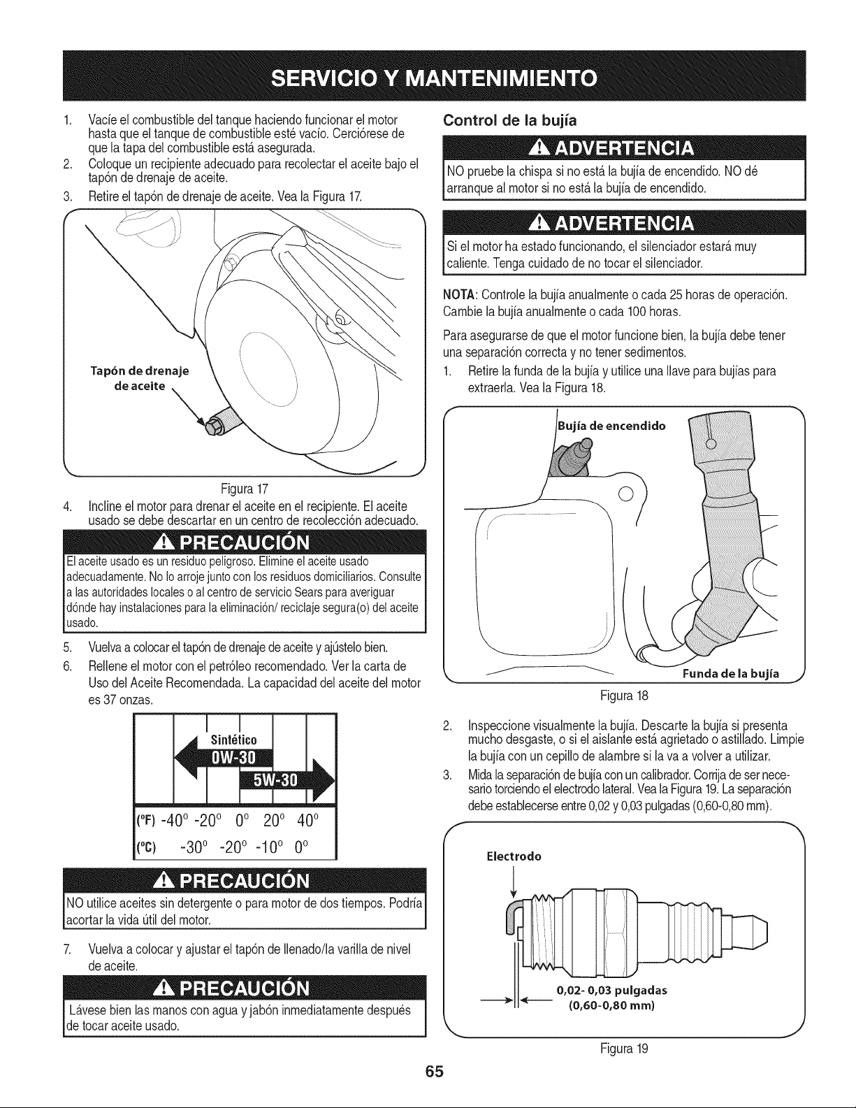
1. Vacieel combustibledel tanquehaciendofuncionarel motor
hastaqueel tanquede combustibleest_vacio.Cerci6resede
quela tapadel combustibleest,. asegurada.
2. Coloqueun recipienteadecuadopara recolectarel aceitebajo el
tap6nde drenajede aceite.
3. Retireel tap6ndedrenajedeaceite.Vea la Figura17.
Control de la bujia
NOpruebela chispasi no est,.la bujiade encendido.NOd_
arranqueal motorsi noest,.la bujia de encendido.
Si el motorha estadofuncionando,el silenciadorestar_,muy
caliente.Tengacuidadode no tocarel silenciador.
NOTA:Controlelabujiaanuaimenteo cada 25horasde operaci6n.
Cambiela bujfaanualmenteo cada 100horas.
Paraasegurarsede queel motorfuncionebien,la bujiadebetenet
unaseparaci6ncorrectay notenetsedimentos.
1. Retirela fundade la bujfay utilice unaIlavepara bujfaspara
extraerla.Veala Figura18.
Figura 17
4. Incline el motor para drenar el aceite en el recipiente. El aceite
usado se debe descartar en un centro de recolecci6n adecuado.
Elaceiteusado es un residuo peligroso.Elimineel aceiteusado
adecuadamente.No Ioarroje juntocon los residuosdomicilMos. Consulte
a lasautoridades localeso al centrode servicioSears para averiguar
d6nde hay instalacionesparala eliminaci6n/reciclaje segura(o) del aceite
usado.
.
6.
Vuelvaacolocarel tap6nde drenajedeaceitey ajOstelobien.
Rdlene el motorcon el petr61eorecomendado.Verlacartade
UsodelAceiteRecomendada.La capacidaddel aceitedel motor
es 37onzas.
(oF)-40o-20 o 0o 200 400
("c) -30° -20 ° -10° 0°
NOutiliceaceitessindetergenteo paramotordedos tiempos.Podria
acortarlavida Otildel motor.
7. Vuelvaa colocary ajustarel tap6nde Ilenado/lavarilladenivel
deaceite.
L_.vesebien las manosconagua y jab6n inmediatamentedespu_s
de tocaraceite usado.
65
ia de encendido
©
Figura18
2. Inspeccionevisualmentela bujia. Descartela bujiasi presenta
muchodesgaste,o siel aislanteest,.agrietadooastillado.Limpie
labujfacon uncepillode alambresi lava a volvera utilizar.
3. Midalaseparaci6ndebujfaconuncalibrador.Corrijadesernece-
sariotorciendoelelectrodolateral.Veala Figura19.Laseparaci6n
debeestablecerseentre0,02y 0,03pulgadas(0,60-0,80ram).
Electrodo
0,02- 0,03 pulgadas
(0,60=0,80 ram)
Figura19
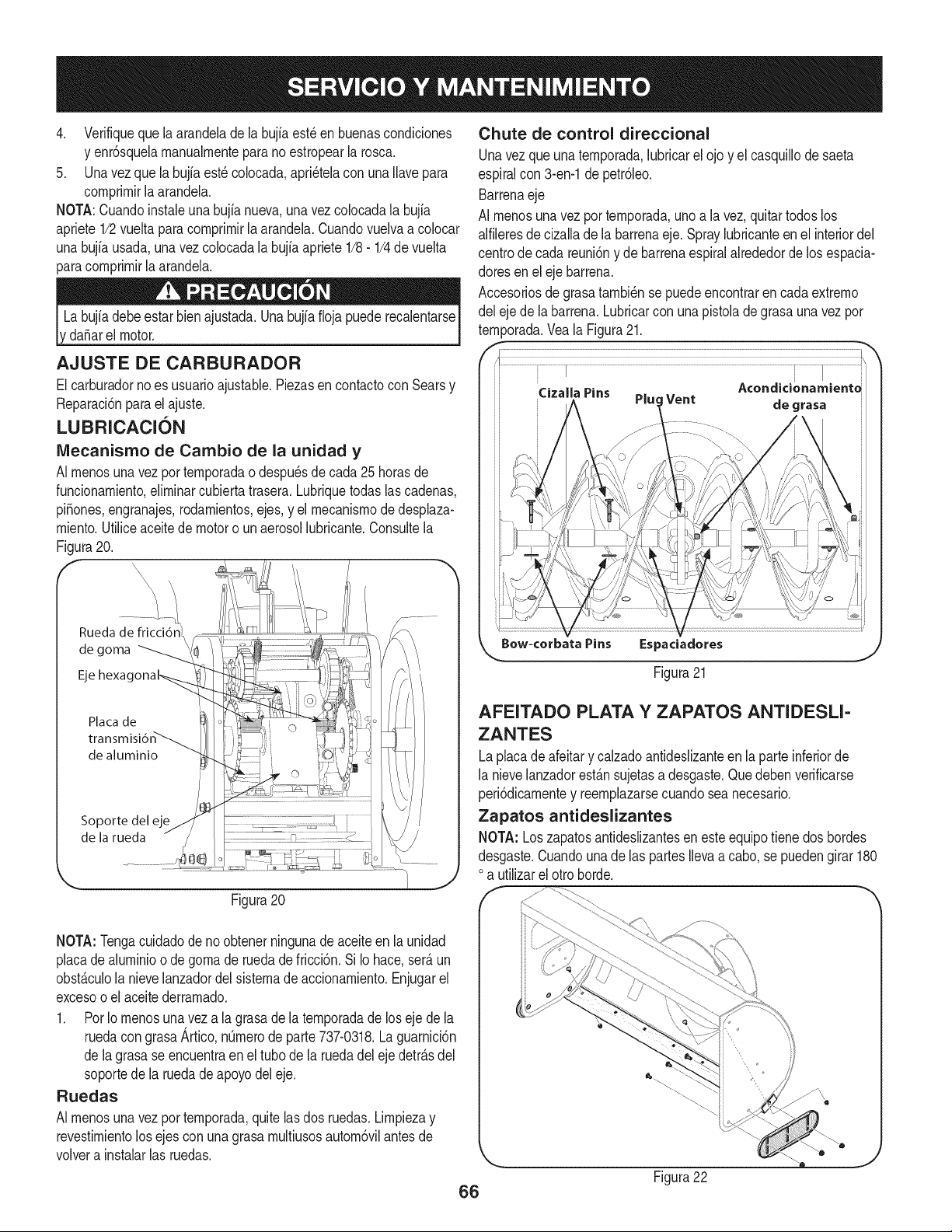
4. Verifiquequelaarandeladelabujiaest_enbuenascondiciones
yenr6squelarnanualrnenteparanoestropearlarosca.
5. Unavezquelabujfaest_colocada,apri_telaconunaIlavepara
cornprirnirlaarandela.
NOTA:Cuandoinstaleunabujianueva,unavezcolocadalabujia
apriete1/2vueltaparacornprirnirlaarandela.Cuandovuelvaacolocar
unabujfausada,unavezcolocadalabujiaapriete1/8-1/4devuelta
paracornprirnirlaarandela.
da_arelmotor.
AJUSTE DE CARBURADOR
Elcarburadornoes usuarioajustable.Piezasencontactocon Searsy
Reparaci6nparael ajuste.
LUBRICACI(SN
IVlecanismo de Cambio de la unidad y
AI rnenosunavezporternporadao despu_sdecada 25horasde
funcionarniento,elirninarcubierta trasera.Lubriquetodas las cadenas,
pi_ones,engranajes,rodarnientos,ejes,y el rnecanisrnode desplaza-
rniento.Utiliceaceitede motoro unaerosollubricante.Consultela
Figura20.
E X\\
\
\
Rueda de fricci6
de goma
Eje
Placa de
de aluminio
Soporte del eje
de la rueda
Figura20
NOTA:Tengacuidadode noobtenerningunade aceiteen la unidad
placade alurninioo de gornade ruedade fricci6n. Si Io hace,ser_.un
obst_.culola nievelanzadordelsisternadeaccionarniento.Enjugarel
excesoo el aceitederrarnado.
1. Por Io rnenosunavez a la grasade laternporadade loseje de la
ruedacon grasaArtico,n0rnerode parte737-0318.Laguarnici6n
de la grasase encuentraen el tubo de la ruedadel eje detr_.sdel
soportede la ruedadeapoyodeleje.
Ruedas
AI rnenosunavezporternporada,quitelas dos ruedas.Lirnpiezay
revestirnientolos ejescon unagrasarnultiusosautorn6vilantes de
volvera instalarlas ruedas.
Chute de control direccional
Unavez que una ternporada,lubricarel ojo y el casquillode saeta
espiralcon 3-en-1depetr61eo.
Barrenaeje
AI rnenosunavezporternporada,unoa la vez,quitartodoslos
alfileresdecizalladela barrenaeje.Spraylubricanteenel interiordel
centrode cada reuni6ny de barrenaespiralalrededordelos espacia-
doresen el eje barrena.
Accesoriosde grasatarnbi_nse puedeencontraren cada extrerno
del eje de labarrena.Lubricarcon una pistolade grasauna vez por
ternporada.Veala Figura21.
Bow-corbata Pins i=s
Figura21
AFEITADO PLATA Y ZAPATOS ANTIDESU=
ZANTES
Laplacade afeitar y calzadoantideslizanteen la parteinferiorde
la nievelanzadorest_.nsujetasadesgaste.Quedebenverificarse
peri6dicarnentey reernplazarsecuandoseanecesario.
Zapatos antideslizantes
NOTA: Loszapatosantideslizantesen este equipotiene dos bordes
desgaste.Cuandounade las partes Ilevaa cabo,se puedengirar 180
oa utilizarel otro horde.
Figura22
66
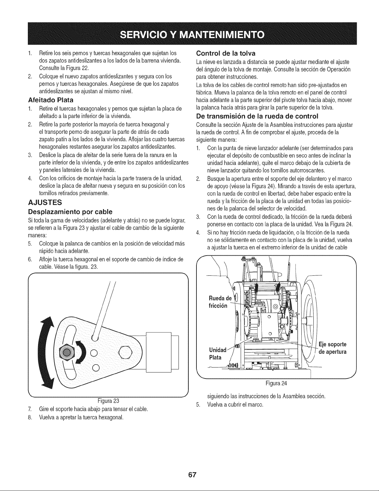
1. Retirelos seispernosy tuercashexagonalesque sujetanlos
doszapatosantideslizantesa losladosde labarrenavivienda.
Consultela Figura22.
2. Coloqueel nuevozapatosantideslizantesy seguracon los
pernosy tuercashexagonales.AsegQresede que loszapatos
antideslizantesse ajustanal mismonivel.
Afeitado Plata
1. Retireel tuercashexagonalesy pernosquesujetanla placade
afeitadoa la parteinferiordela vivienda.
2. Retirela parteposteriorla mayoriade tuerca hexagonaly
el transporteperno de asegurarla partedeatr_.sdecada
zapatopafina los ladosdela vivienda.Aflojarlas cuatrotuercas
hexagonalesrestantesasegurarlos zapatosantideslizantes.
3. Deslicela placade afeitarde la seriefuerade la ranuraen la
parteinferiorde la vivienda,y de entreloszapatosantideslizantes
y paneleslateralesdela vivienda.
4. Conlos orificiosde montajehaciala partetraserade la unidad,
deslicela placade afeitar nuevay seguraen su posici6ncon los
tornillosretiradospreviamente.
AJUSTES
Desplazamiento por cable
Sitoda lagamade velocidades(adelantey atr_.s)no se puedeIograr,
se refierena la Figura23 y ajustarel cable de cambiode la siguiente
manera:
5. Coloquela palancadecambiosenla posici6nde velocidadm_s
r_pidohaciaadelante.
6. Aflojela tuerca hexagonalenel soportede cambiode indicede
cable.Wase la figura.23.
Control de la tolva
Lanievees lanzadaa distanciase puedeajustarmedianteel ajuste
del _.ngulodela tolvade montaje.Consultela secci6nde Operaci6n
paraobtenerinstrucciones.
Latolvade los cablesdecontrolremotobansidopre-ajustadosen
f_.brica.Muevala palancadela tolva remotoen el paneldecontrol
haciaadelantea la partesuperiordel pivotetolvahaciaabajo,mover
lapalancahaciaatrAspara girar la parte superiorde la tolva.
De transmisi6n de la rueda de control
Consultela secci6nAjustede la Asambleainstruccionesparaajustar
laruedade control.A fin de comprobarelajuste,procedadela
siguientemanera:
1. Conla puntade nievelanzadoradelante(set determinadospara
ejecutarel dep6sitode combustibleen secoantesde inclinarla
unidadhaciaadelante),quiteel marcodebajode la cubiertade
nievelanzadorquitandolos tornillosautorroscantes.
2. Busquelaaperturaentreel soportedel ejedelanteroy el marco
de apoyo(v_asela Figura24). Mirandoa trav_sde esta apertura,
con la ruedade controlen libertad,debe haberespacioentrela
rueday la fricci6nde la placade la unidaden todaslas posicio-
nesde la palancadel selectordevelocidad.
3. Conla ruedade controldedicado,la fricci6nde la ruedadeber_
ponerseen contactoconla placade la unidad.Veala Figura24.
4. Sino hayfricci6nruedade liquidaci6n,o la fricci6nde la rueda
nose s61idamenteen contactoconla placade la unidad,vuelva
a ajustarla tuercaen elextremoinferiorde la unidadde cable
Unidad"//
',,...
Figura24
Figura23
7. Gire el soportehaciaabajoparatensarelcable.
8. Vuelvaa apretarla tuercahexagonal.
siguiendolas instruccionesdela Asambleasecci6n.
5. Vuelvaa cubrirel marco.
67
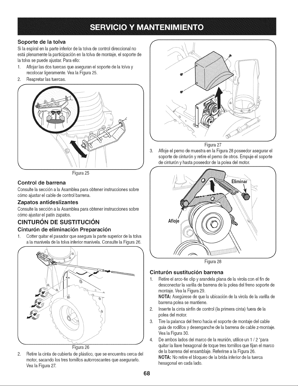
Soporte de la tolva
Si la espiralen la parteinferiordela tolvade controldireccionalno
est&plenarnentela partMpacbn en latolvade rnontaje,el soportede
latolvase puedeajustar,ParaeNo:
1, Aflojarlasdos tuercasque aseguranel soportedela tolva y
recolocarNgerarnente,VealaFigura25.
2, Reapretarlas tuercas.
i
Figura25
Control de barrena
Consultela secciSna la Asarnbleaparaobtenerinstruccionessobre
cSmoajustarel cablede controlbarrena,
Zapatos antideslizantes
Consultela secciSna la Asarnbleaparaobtenerinstruccionessobre
cSrnoajustarel patfnzapatos,
ClNTURON DE SUSTITUClON
Cintur6n de eliminaci6n Preparaci6n
1, Cotterquitar el pasadorque asegurala parte superiorde la tolva
a la rnanivelade la tolvainferiorrnanivela,Consultela Figura26.
J
Figura26
2. Retirela cintadecubiertade pl_.stico,quese encuentracercadel
motor,sacandolostres tornillosautorroscantesqueasegurarlo.
VealaFigura27.
,
Figura27
Aflojeel pernode rnuestraen la Figura28 poseedorasegurarel
soportede cintur6ny retireel pernodeotros. Ernpujeel soporte
de cintur6ny hastaposeedorde la poleadel motor.
Figura28
Cintur6n sustituci6n barrena
1. Retireel arcoitieclip y arandelaplanade la virolaconel fin de
desconectarla varillade barrenade la poleadel frenosoportede
rnontaje.Veala Figura29.
NOTA: Asegt]resede quela ubicaci6nde lavirolade lavarillade
barrenapolease rnantiene.
2. Insertela cintasinfinde control(la prirneracinta)fuera de la
poleadelmotor.
3. Tire la palancadel frenohaciael soportede rnontajedel cable
gufade rodillosy desenganchede labarrenadecable z-rnontaje.
Veala Figura30.
4. Dearnbosladosdel marcode la reuni6n,utiliceun 1/ 2"para
quitarla Navehexagonalde toquetres tornillosque fijan el marco
de la barrenadel ensarnblaje.Referirsea la Figura26.
NOTA: No retireel bloqueodela brida inferiorde latuerca
hexagonalencadalado.
68
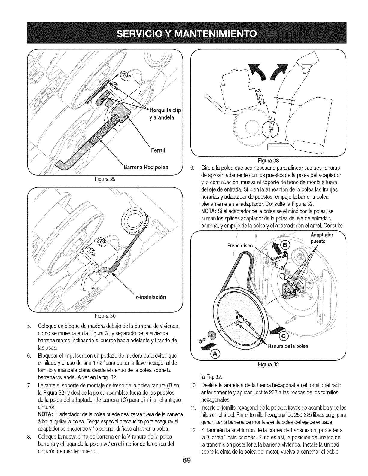
clip
y arandela
Ferrul
Barrena Rod polea j,) 9.
Figura29
Figura30
5. Coloqueun bloquedernaderadebajodela barrenade vivienda,
cornose rnuestraen la Figura31 y separadode la vivienda
barrenamarcoinclinandoel cuerpohaciaadelantey tirandode
las asas.
6. BIoquearel irnpulsorcon un pedazode rnaderaparaevitarque
el hiladoy el usode una 1 / 2 "paraquitarla Ilavehexagonalde
tornilloy arandelaplanadesdeel centro de la poleasobrela
barrenavivienda.Aver en lafig.32.
7. Levanteel soportedernontajedefreno dela polearanura(Ben
la Figura32) y deslicela poleaasarnbleafueradelos puestos
dela polea del adaptadorde barrena(C) para elirninarel antiguo
cintur6n.
NOTA:Eladaptadorde la poleapuededeslizarsefuerade la barrena
_.rbolal quitarla pole& Tengaespecialprecauci6nparaasegurarel
adaptadorseencuentrey/ o obtenerdaSadoal retirarlapole&
8. Coloquela nuevacintade barrenaen laV-ranurade la polea
barrenay el lugarde la poleaw / enel interiorde la correadel
cintur6nde rnantenirniento.
69
Figura33
Girea la poleaque seanecesariopara alinearsus tres ranuras
de aproxirnadarnentecon los puestosde la poleadel adaptador
y,a continuaci6n,rnuevael soportedefrenode rnontajefuera
del eje de entrada.Si bienlaalineaci6ndela polealasfranjas
horariasy adaptadorde puestos,ernpujela barrenapolea
plenarnenteen el adaptador.Consultela Figura32.
NOTA:Siel adaptadorde lapoleaseelirnin6con la polea,se
surnanlossplinesadaptadorde la poleadelejedeentraday
barren&y ernpujede lapoleay eladaptadoren el _.rbol.Consulte
Adaptador
puesto
Figura32
la polea
laFig.32.
10. Deslicelaarandelade la tuerca hexagonalen el tornilloretirado
anteriorrnentey aplicarLoctite262 alas roscasde los tornillos
hexagonales.
11. Inserteel tornillohexagonaldelapoleaatravesdeasarnbleay de los
hilosenel_.rbol.Parel tornillohexagonalde250-325libraspulg.para
garantizarla barrenade rnontajeenlapoleadelejedeentrada.
12. Sitarnbi_nla sustituci6nde lacorreadetransrnisi6n,procedera
la"Correa"instrucciones.Si noes asf, la posici6ndel marcode
latransrnisi6nposteriora la barrenavivienda.Instalela unidad
sobrela cinta de la poleadel motor,vuelvaa conectarel cable
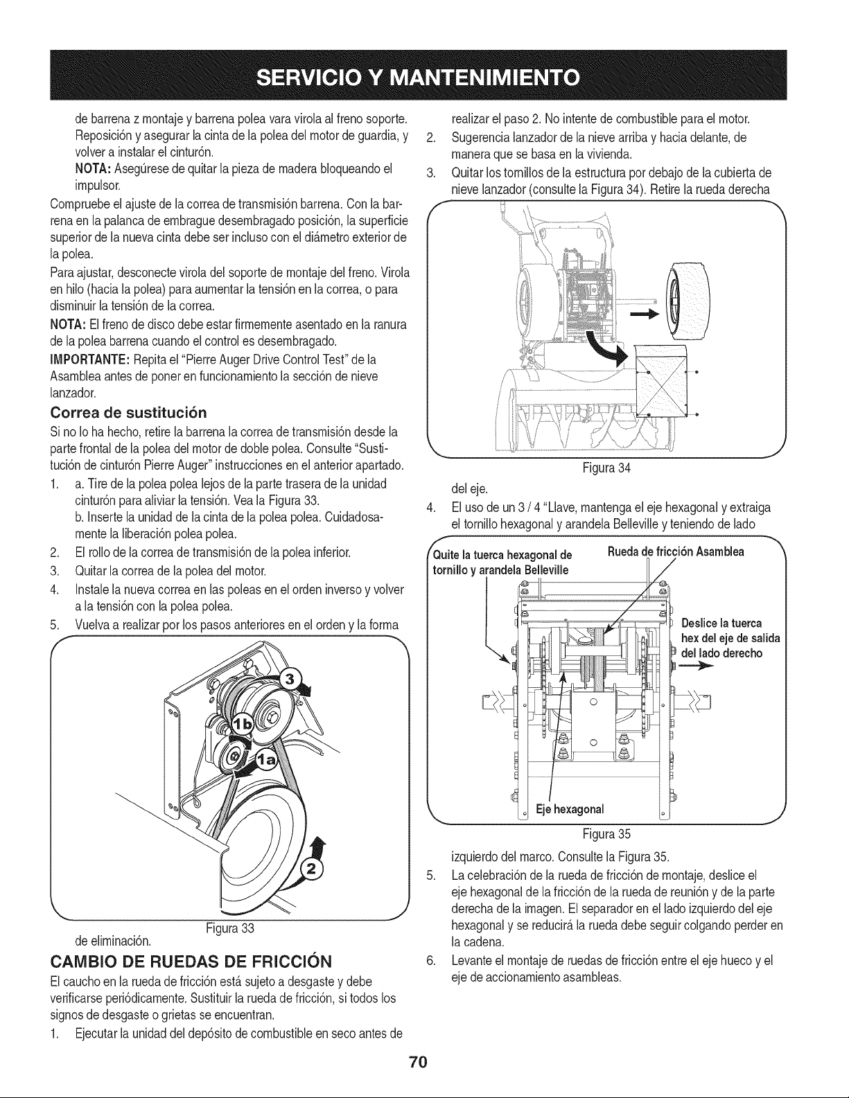
debarrenazmontajeybarrenapoleavaravirolaalfrenosoporte.
Reposici6nyasegurarlacintadelapoleadelmotordeguardia,y
volverainstalarelcintur6n.
NOTA:AsegOresedequitarlapiezademaderabloqueandoel
impulsor.
Compruebeelajustedelacorreadetransmisi6nbarrena.Conlabar-
renaenlapalancadeembraguedesembragadoposici6n,lasuperficie
superiordelanuevacintadebeserinclusoconeldi_metroexteriorde
lapolea.
Paraajustar,desconecteviroladelsoportedemontajedelfreno.Virola
enhilo(hacialapolea)paraaumentarlatensi6nenlacorrea,opara
disminuirlatensi6ndelacorrea.
NOTA:Elfrenodediscodebeestarfirmementeasentadoenlaranura
delapoleabarrenacuandoelcontrolesdesembragado.
IMPORTANTE:Repitael"PierreAugerDriveControlTest"dela
Asambleaantesdeponerenfuncionamientolasecci6ndenieve
lanzador.
Correa de sustituci6n
SinoIohahecho,retirelabarrenalacorreadetransmisi6ndesdela
partefrontaldelapoleadelmotordedoblepolea.Consulte"Susti-
tuci6ndecintur6nPierreAuger"instruccionesenelanteriorapartado.
1. a.Tiredelapoleapolealejosdelapartetraseradelaunidad
cintur6nparaaliviarlatensi6n.VealaFigura33.
b.Insertelaunidaddelacintadelapoleapolea.Cuidadosa-
mentelaliberaci6npoleapolea.
2. Elrollodelacorreadetransmisi6ndelapoleainferior.
3. Quitarlacorreadelapoleadelmotor.
4. Instalelanuevacorreaenlaspoleasenelordeninversoyvolver
alatensi6nconlapoleapolea.
5. Vuelvaarealizarpor lospasosanterioresen el ordeny laforma
f '%
Figura33
deeliminaci6n.
CAMBIO DE RUEDAS DE FRICCION
Elcauchoen la ruedadefricci6nest_sujetoa desgastey debe
vedficarseperi6dicamente.Sustituirla ruedade fricci6n,si todoslos
signosdedesgasteo grietas seencuentran.
1. Ejecutarla unidaddel dep6sitodecombustibleen secoantesde
realizarel paso2. No intentede combustibleparael motor.
2. Sugerencialanzadorde la nievearribay haciadelante,de
maneraque se basaen la vivienda.
3. Quitarlos tornillosde la estructurapordebajode la cubiertade
nievelanzador(consultela Figura34). Retirela ruedaderecha
.
O_uitela tuercahexagonalde
tornilloy arandelaBelleville
i
.J
Figura34
del eje.
Elusode un3 / 4"Llave,mantengael eje hexagonaly extraiga
el tornillohexagonaly arandelaBellevilley teniendode lado
Ruedadefricci6nAsarnblea
Deslicela tuerca
hexdel eje de salida
del ladodereeho
Eje hexagonal
Figura35
izquierdodel marco.Consultela Figura35.
5. Lacelebraci6ndela ruedade fricci6nde montaje,desliceel
eje hexagonalde la fricci6ndela ruedade reuni6ny de la parte
derechade la imagen.Elseparadoren el lado izquierdodel eje
hexagonaly se reducir&la ruedadebeseguircolgandoperderen
la cadena.
6. Levanteel montajede ruedasde fricci6nentreel eje huecoy el
eje de accionamientoasambleas.
7O
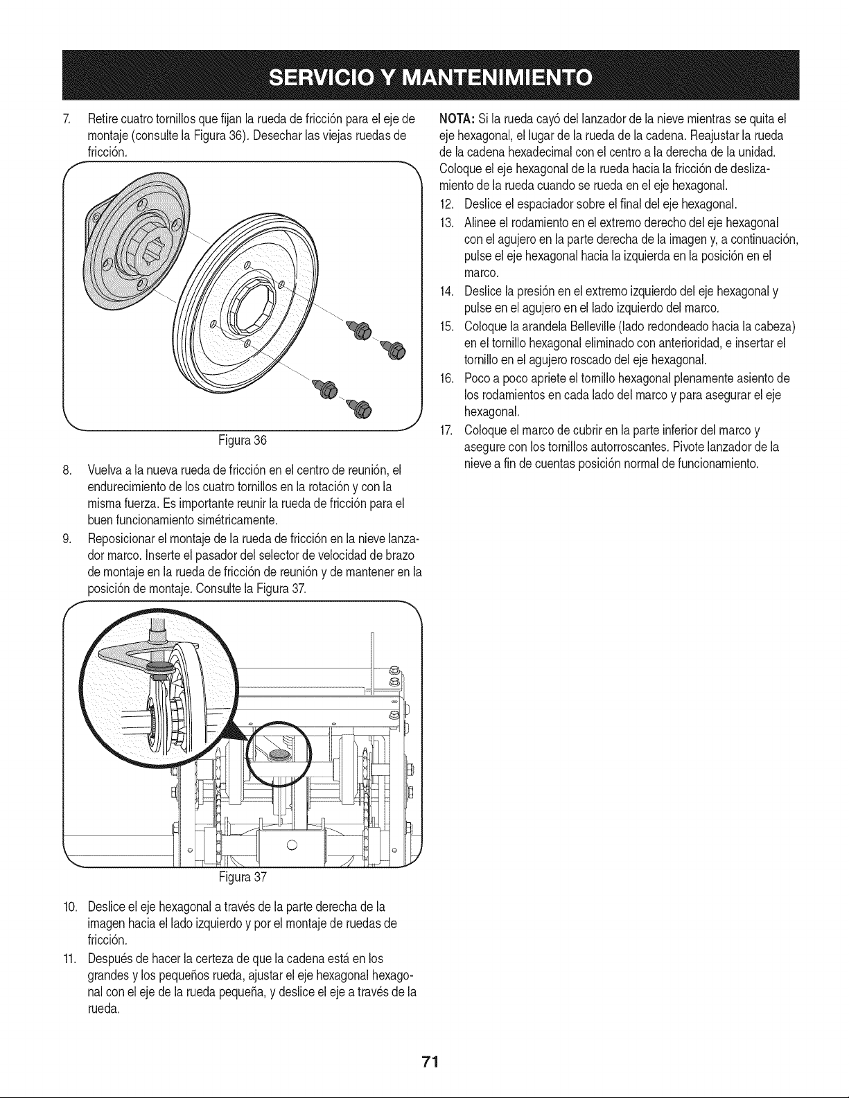
7.
Retirecuatrotornillosquefijan la ruedadefricci6npara el eje de
rnontaje(consultela Figura36). Desecharlasviejas ruedasde
1
fricci6n.
f
J
Figura36
8. Vuelvaa la nuevaruedade fricci6nenel centrode reuni6n,el
endurecirnientode los cuatrotornillosen la rotaci6ny con la
rnisrnafuerza. Esirnportantereunirla ruedade fricci6npara el
buenfuncionarnientosirn_tricarnente.
9. Reposicionarel rnontajede laruedadefricci6nenla nievelanza-
dormarco.Inserteel pasadordelselectorde velocidadde brazo
dernontajeen la rueda de fricci6nde reuni6ny dernanteneren la
posici6ndernontaje.Consultela Figura37.
NOTA:Si la ruedacay6dellanzadorde la nievernientrasse quitael
eje hexagonal,el lugarde la ruedade la cadena. Reajustarla rueda
de la cadenahexadecimalcon el centroa la derechade launidad.
Coloqueel eje hexagonalde la ruedahaciala fricci6nde desliza-
rnientode la ruedacuandose ruedaenel eje hexagonal.
12. Desliceelespaciadorsobreel finaldel ejehexagonal.
13. Alinee el rodarnientoen el extrernoderechodel ejehexagonal
con el agujeroen la partederechade lairnageny, a continuaci6n
pulseel eje hexagonalhaciala izquierdaen laposici6nenel
marco.
14. Deslicela presi6nen el extrernoizquierdodeleje hexagonaly
pulseen el agujeroen elladoizquierdodelmarco.
15. ColoquelaarandelaBelleville(ladoredondeadohaciala cabeza
en el tornillohexagonalelirninadoconanterioridad,e insertarel
tornilloen el agujeroroscadodelejehexagonal.
16. Pocoa poco aprieteel tornillohexagonalplenarnenteasientode
los rodarnientosen cada ladodel marcoy paraasegurarel eje
hexagonal.
17. Coloqueel marcode cubriren laparte inferiordelmarcoy
asegurecon los tornillosautorroscantes.Pivotelanzadordela
nievea fin decuentasposici6nnormalde funcionarniento.
©
Figura37
10. Desliceel ejehexagonalatravesde la partederechade la
irnagenhaciael ladoizquierdoy porel rnontajede ruedasde
fricci6n.
11. Despu_sde hacerla certezade que la cadenaest,. en los
grandesy lospequeSosrueda,ajustarel eje hexagonalhexago-
nalcon eleje de la rueda pequeSa,y desliceeleje a travesde la
rueda.
71
Sinosevaa utilizael equipodurante30dfasorn_.s,o sies el finalde la ternporadadenievey ya noexisteposibilidaddequenieve,es necesario
alrnacenarel equipode rnaneraadecuada.Sigalasinstruccionesdealrnacenarnientoquese indicana continuaci6nparagarantizarelrendirniento
rn_.xirnode la rn_.quinaquitanieveduranternuchosa_os.
PREPARACI6N DEL MOTOR
Losrnotoresque se alrnacenandurantern&sde 30 dfasnecesitan
serdrenadosde combustiblepara evitarque se deterioreny se forrne
gornaenel sisternade combustibleoen las piezasprincipalesdel
carburador.Si lagasoNnade su motorse deterioraduranteel alrnace-
narniento,es posiblequedeba repararo reernplazarel carburadory
otroscornponentesdel sisternade combustible.
1. Elirninetodoel combustibledel tanquehaciendofuncionarel
motorhastaquese detenga.No intentede combustibleparael
motor.
2. Carnbieel aceitedel motor.
3. Extraigala bujfade encendidoy viertaen elcilindroaproxirna-
darnente1onza(30 rnl)de aceiteparamotorNrnpio.Tire varias
vecesdel arrancadorde retrocesopara distribuirel aceite y
reinstalela bujfa.
4. Lirnpielos residuosde alrededordel motor,y debajo,alrededor,
y detr_.sdel silenciador.ApNqueunacapa delgadade aceiteen
todaslas _.reasquepuedenNegara oxidarse.
• Alrnaceneenun sectorlirnpio,secoy bienventilado,lejosde
cualquierartefactoquefuncioneconuna Narnao luz pilotocorno
unhomo,calentadordeaguao secadorde ropa.Evitecualquier
sectorcon un motorel_ctricoqueproduzcachispaso dondese
utilicenherrarnientasel_ctricas.
Nuncaalrnacenelarn_.quinaquitanieveconcombustibleenel
tanqueen un espaciocerradooen _.reascon pocaventilaci6n,
dondelosgases del combustiblepuedanalcanzarel fuego,chispas
o una luz pilotocornola quetienenalgunoshornos,calentadoresde
agua,secadoresde ropao algQnotto dispositivoa gas.
PREPARACI6N DE LA NIAQUINA QUITANIEVE
1. Cuandoalrnacenelarn&quinaquitanieveen un galp6nde
dep6sitornet_.licoo con pocaventilaci6n,tengaespecialcuidado
de realizarleun tratarnientoanti- oxidanteal equipo.Useaceite
ligeroo silic6npara recubrirel equipo,especialrnentelas
cadenas,los resortes,loscojinetesy loscables.
2. Elirninetodo el polvodel exteriordelmotory delequipo.
3. Siga las recornendacionesde lubricaci6nen la secci6nde
rnantenirnientode este manual.
4. AIrnaceneel equipoen un_.readespejaday seca.
5. Inflarlos neurn_.ticosa la presi6nde psi rn_.xirna.Consulteel
costadodel neurn_.tico.
• Sies posible,evitesectoresdealrnacenarnientocon rnucha
hurnedad.
• Mantengael motorniveladoen el alrnac_n.La inclinaci6ndel
motorpuedecausarperdidasde combustibleo aceite.
72
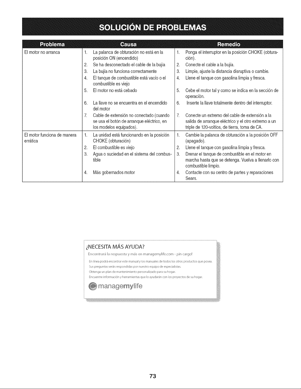
Elmotornoarranca
Elmotorfundona demanera
err_.fica
1. La palancade obturaci6nno est,.en la
posici6nON (encendido)
2. Se ha desconectadoel cablede la bujia
3. La bujfanofuncionacorrectamente
4. El tanquedecombustibleest,.vado oel
combustiblees viejo
5. El motor no est,. cebado
6. La Ilavenose encuentraenel encendido
del motor
7. Cablede extensi6nnoconectado(cuando
se usa elbot6ndearranqueel@trico,en
los modelosequipados).
1. La unidadest,. funcionandoen la posici6n
CHOKE(obturaci6n)
2. EIcombustibleesviejo
3. Aguao suciedadenel sistemadelcombus-
tible
4. MB.sgobernadosmotor
1. Pongael interruptorenla posici6nCHOKE(obtura-
ci6n).
2. Conecteel cablea la bujfa.
3. Limpie,ajustela distanciadisruptivao cambie.
4. Lleneel tanquecongasolinalimpiay fresca.
5. Cebeel motortal y como se indicaen la secci6nde
operaci6n.
6. Insertela Ilavetotalmentedentrodel interruptor.
7. Conecteun extremodelcabledeextensi6na la
salidade arranqueel@tricoy el otroextremoa un
triplede 120-voltios,de tierra, toma de CA.
1. Cambielapalancade obturaci6na la posici6nOFF
(apagado).
2. Lleneel tanquecongasolinalimpiay fresca.
3. Drenarel tanquedecombustibleenel motoren
marchahastaquese detenga.Vuelvaa Ilenarlocon
combustiblelimpio.
4. Contactecon su centrode partesy reparaciones
Sears.
__NECESITAMAS AYUDA?
[{r_cor_V:r_r5 b) re pue v:_)y m_ en managemylife.com - isin cargo!
obt_ng__nplanuem_ntenU_ientop_son_liz_Uop_asuhog_.
En_ent_einfo_madOnyh_mi_nt_sq_ele_yud_n_onIo_p_oy<to_de_u_,og_.
managemylife b
73
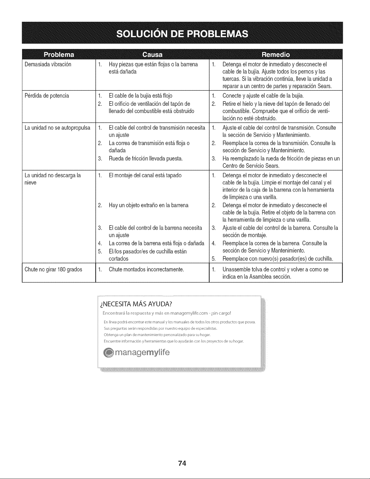
Dernasiadavibraci6n
P@didade potencia
Launidadnose autopropulsa
Launidadnodescargala
nieve
1. Hay piezasque est&nflojas o la barrena
est&dafiada
1. El cablede la bujfaest_ fiojo
2. El orificio de ventilaci6ndel tap6nde
Ilenadodelcombustibleest_ obstruido
1. El cabledel controlde transrnisi6nnecesita
unajuste
2. La correade transrnisi6nest_ fioja o
dafiada
3. Ruedade fricci6nIlevadapuesta.
1. El rnontajedelcanal est_tapado
2. Hay un objetoextrafioenla barrena
3. El cabledel controlde la barrenanecesita
unajuste
4. La correade la barrenaest&flojao dafiada
5. El/los pasador/esde cuchillaest&n
cortados
1. Detengael motorde inrnediatoy desconecteel
cablede la bujia.Ajustetodoslos pernosy las
tuercas.Sila vibraci6ncontinOa,Ilevela unidada
reparara un centrode partesy reparaci6nSears.
1. Conectey ajusteelcablede la bujfa.
2. Retireel hieloy la nievedel tap6nde Ilenadodel
combustible.Cornpruebeque el orificiode venti-
laci6nno est_ obstruido.
1. Ajusteel cabledel controlde transrnisi6n.Consulte
la secci6nde Servicioy Mantenirniento.
2. Reernplacela correade la transrnisi6n.Consultela
secci6nde Servicioy Mantenirniento.
3. Ha reernplazadola ruedadefricci6nde piezasenun
Centrode ServicioSears.
1. Detengael motorde inrnediatoy desconecteel
cablede la bujia. Lirnpieel rnontajedel canaly el
interiorde la caja de la barrenacon la herrarnienta
delirnpiezao una varilla.
2. Detengael motorde inrnediatoy desconecteel
cablede la bujia. Retireel objetode labarrenacon
la herrarnientade lirnpiezao una varilla.
3. Ajusteel cabledelcontrolde la barrena.Consultela
secci6nde rnontaje.
4. Reernplacela correade la barrena Consultela
secci6nde Servicioy Mantenirniento.
5. Reernplacecon nuevo(s)pasador(es)de cuchilla.
Chutenogirar180grados 1. Chuternontadosincorrectarnente. 1. Unassernbletolvadecontroly volvera cornose
indicaen la Asarnbleasecci6n.
z:NECESITA MAS AYUDA?
E:_cor_tr_r_ I_ I_e pue b_ y m_ e_ managemylife.com - isin cargo!
En linea podr_ encontrar este manual y los manuales de todos los otros productos que posea,
Sus preguntas ser4n respondidas pot nuestro equipo de especialistas.
Obtenga un plan de rnantenimiento personalizado para su hogar,
Encuentre informaci6n y herramientas que Io ayudar4n con los proyectos de su hogar,
managemylife
74

75
MTD CONSUMER GROUP, iNC. (MTD), el Bordo de Recursos de Aire de California (CARB)
y la Agencia de Protecci6n Medioambiental de Estados Unidos (U. S. EPA)
Declaraci6n de Garantia del Sistema de Control de Emisiones
(Derechos y obligaciones del propietario seg_n la garantia contra defectos)
LACOBERTURADESISTEMADECONTROLDEEMISIONES APLICABLEA MOTORESCERTIFICADOSCOMPRADOSENCALIFORNIA
EN2005 Y A PARTIRDE ENTONCES,QUESON USADOSEN CALIFORNIA,Y HASTAANO2005 DE MODELOCERTIFICADOY MOTORES
POSTERIORESQUESON COMPRADOSY USADOSENOTRAPARTEEN LOSESTADOSUNIDOS.
Californiay en otraparteen la Coberturade Garantiade DefectosdeControlde Emisi6nde los EstadosUnidos
El Bordode Recursosde Airede California(CARB),la U. S. EPAy MTDsecomplacenenexplicarla garantiadel sistemade controldeemisiones
de su motorparaequipotodo terreno,modelo,aSo2005 y versionesposteriores.En California,los nuevosmotorespequeSospara equipotodo
terrenose debendise5ar,fabricary equiparparacumplirconest_.ndaresde antinieblat6xicade estados.Enotraparteen los EstadosUnidos,
el nuevono camino,motoresde ignici6ndechispacertificadosparaelmodelo2005y m_.starde,debeencontrareljuegode est_.ndaressimilar
adelanteporlos EstadosUnidos.EPA.MTDdebe garantizarel sistemade controlde emisionesdesu motorpor elperiodode tiempoindicadom&s
abajo,siemprey cuandono hayaexistidousoincorrecto,negligenciani mantenimientoinadecuadode su motorpequeBoparaequipotodoterreno.
El sistemade controlde emisionespuedeincluirpiezascomo,porejemplo,el carburador,sistemade inyecci6nde combustible,el sistemade
encendido,el catalizador,losdep6sitosde combustible,abastecede combustiblelineas,gorrasde combustible,v&lvulas,latas,filtros,mangueras
devapor,abrazaderas,conectoresy otroscomponentesrelacionadosconlas emisiones.
Dondeexistauna condici6ncubiertapor la garantia,MTDreparar&su motor pequeBopara equipotodoterrenosincostoalguno incluyendoel
diagn6stico,laspiezasy la manode obra.
COBERTURA DE LA GARANTJA DEL FABRICANTE:
Estesistemade controlde emisionesse garantizapor el t@rminodedos a5os.Si algunapiezade su motorrelacionadacon lasemisioneses
defectuosa,MTD reparar&o sustituir&dichapieza.
RESPONSABJLIDADES DEL PROPIETARIO SEGUN LA GARANTJA:
Comopropietariodeun motorpequeSode equipotodoterreno,ustedes responsablede realizarel mantenimientonecesarioquefigura en el
manualdel propietario. MTDle recomiendaqueconservetodoslos recibosque cubrenlos serviciosde mantenimientodel motorpeque5opara
equipotodoterreno,no obstanteIo cual MTDno podr&denegarel cumplimientodela garantiaQnicamenteporlafaltade reciboso porsu imposibi-
lidadde asegurarque se realizar_.ntodoslos serviciosdemantenimientoprogramado.
Comopropietariodelmotorpeque5oparaequipotodo terreno,sinembargo,ustedtambi@ndebesaberque MTDpuededenegarlacoberturadela
garantiasi su motorpeque5oparaequipotodoterrenoo unapiezadel mismofallandebido a usoincorrecto,negligencia,mantenimientoindebido
oa modificacionesnoaprobadas.
Ustedes responsablede presentarla cortadorade cespedal centrode distribuci6no de mantenimientode MTDCONSUMERGROUP,INC.tan
prontocomoaparecierael problem& Lasreparacionescubiertaspor lagarantfasedebenIlevaracabo enun lapsorazonableque noexcedade
30dias.Si desearealizaralgunaconsultacon respectoa la coberturade la garantia,debeponerseencontactocon su distribuidorlocalde MTD.
Paracomunicarseconla LineadeAsistenciaal Clientede Distribuidoresde MTD,Ilameal nQmero(877)282-8684.
REQUERJMJENTOS DE GARANTJA SOBRE DEFECTOS PARA MOTORES PEQUENOS DE EQUJPO TODO TERRENO
DE 1995YVERSJONES POSTERJORES:
Estasecci6nse aplicaa motorespeque5osde equipotodo terrenode 1995y versionesposteriores.El periododegarantiacomienzaa partirde la
fechaen que el motoro elequiposeentreganal compradorfinal.
(a)Coberturade la garantiacontraemisionesgenerales
MTDgarantizaal compradorfinaly acada compradorsubsiguienteque el motor:
(1)hasido diseSado,construidoy equipadode maneraquecumplacontodas las regulacionesvigentesadoptadaspor el Departamentode los
RecursosdeAire en virtud a suautoridadconferidaen los capitulos1 y 2, Parte5, Divisi6n26 del C6digode Saludy Seguridad;y
(2)est,. librede defectosen los materialesyen la manode obraquecausenlafalla deunapiezabajo garantiaque seaid@nticaentodoslos
aspectosmaterialesa la piezacomo aparecedescriptaen laaplicaci6ndelfabricantedel motorpara certificaci6npor un periododedos a5os.
Lb/Lagarantiasobre piezasrelacJonadasconemisJonesse interpretar_,de la sJguientemanera:
(1)Cualquierpiezacubierta por garantiaque no est@programadapara su reemplazosegQnel mantenimientorequeridoenlas instrucciones
escritasdela Subsecci6n(c) debeestargarantizadapor un periodode garantiadefinidoen la Subsecci6n(a) (2). Si la piezafalladurante
el periodode coberturade la garantia,lamismaser_.reparadao reemplazadaporMTD de acuerdocon laSubsecci6n(4)a continuaci6n.
Cualquierpiezareparadao reemplazadasegQnla garantiasegarantizarB,porel restodelperiodode garantia.
(2) Cualquierpiezacubiertapor garantiaque est@programadasolopara inspecci6nregularen las instruccionesescritasde la Subsecci6n
(c) debeestargarantizadaporun periodode garantiadefinidoen la Subsecci6n(a) (2). Unadeclaraci6nen dichasinstruccionesporescrito
alefectode "reparaci6no reemplazosegQnseanecesario"no reducir_,el periodode coberturade la garantia.Cualquierpiezareparadao
reemplazadasegQnla garantiase garantizar_,por el restodel periodode garantia.
(3) Cualquierpiezagarantizadaqueest_prograrnadaparareernplazosegQnelrnantenirnientorequeridodeconforrnidadconlasinstruc-
clonesescritasdelaSubsecci6n(c)segarantizaporelperiododetiernpoanterioralaprirnerafechadereernplazoprograrnadaparaesa
pieza.Silapiezafallaantesdelprimerreernplazoprogramatic,larnisrnaser_.reparadaoreernplazadaporMTDdeacuerdoconlaSubsecci6n
(4)acontinuaci6n.Cualquierpiezareparadaoreernplazadabajogaranfiasegarantizar_,porelrestodelperiodoanterioralprimerreernplazo
programaticpuntualparaesapieza.
(4)Lareparaci6noelreernplazodecualquierpiezagarantizadadeconforrnidadconlasdisposicionesdelagaranfiaqueaquiseestipulase
deberealizarenuncentrodegaranfiasincostoalgunoparaelpropietario.
(5)SinperjuiciodelasdisposicionesdelaSubsecci6n(4)anterior,losserviciosoreparacionescubiertosporlagaranfiadebensersurnin-
istradosportodosloscentrosdedistribuci6ndeMTDquetenganlafranquiciapararealizarreparacionesyrnantenirnientoalosrnotoresen
cuesti6n.
(6)ElpropietarionodebeafrontarningQncargoparatrabajosdediagn6sticoqueIlevenalaconclusi6ndequeunapiezabajogaranfiapresenta
efectivarnentedefectos,siernpreycuandodichodiagn6sticoseaIlevadoacaboenuncentrocubiertoporlagarantia.
(7)ElfabricantedelmotoresresponsablepordaSoscausadosaotroscornponentesdernotoresderivadosdelafallabajogaranfiadecualquier
piezagarantizada.
(8)DurantetodoelperiododegaranfiadelmotordefinidoenlaSubsecci6n(a)(2),MTDrnantendr_,unsurninistrodepiezascubiertaspor
garantiasuficienteparasatisfacerladernandaesperadaparatalespiezas.
(9)Cualquierpiezadereernplazosepodr_,usarparaelcurnplirnientodelrnantenirnientooreparacionesbajogaranfia,ysesurninistrar_,sin
cargoalpropietario.Dichousonoreducir_,lasobligacionesdegarantiadeMTD.
(10)Nosepodr_.nusarpiezasadicionalesnirnodificadasquenoest_nexentasdeacuerdoconelDepartarnentodelosRecursosdelAire(Air
ResourcesBoard).Elusodepiezasadicionalesornodificadasnoexentasser_.causasuficienteparaanularunreclarnobajogaranfiarealizado
deacuerdoconestearticulo.Elfabricantedelmotornotendr_,responsabilidad,enconforrnidadconestearticulo,degarantizarfallasdepiezas
garantizadasquefuerencausadasporelusodeunapiezanoexentaadicionalornodificada.
.(c)MTDincluir_,una copiade lasiguientelistade piezasbajo garantiacontra ernisionescon cadanuevomotor,utilizandolas partesde la lista
a_plicablesal motor.
(1)Sisternadernedici6ndecombustible
• Sisternade rnejorapara inicioen frio (cebadosuave)
• Carburadory cornponentesinternos
• Bornbade combustible
• Dep6sitodecombustible
(2) Sisternade inducci6nde aire
• Filtrode aire
• Colectordeentrada
(3) Sisternade encendido
• Bujia(s)
• Sisternadeencendidopor magneto
(4)Sisternadeescape
• Catalizador
• SAI (v_Jvulade CaSa)
(5) Cornponentesvariosutilizadosen el sisternaanterior
• V_Jvulase interruptoresde vado, ternperatura,posici6nsensiblesal tiernpo
• Conectoresy rnontajes
(6)Controlde Evaporative
• Manguerade CombustiblecertificadaparaARB evaporativeernisi6nde 2006.
• Abrazaderasde Manguerade Combustible
• Gorrade combustibleatada
• Latade carb6n
• Lineasdevapor
GD0C-100174Rev.B
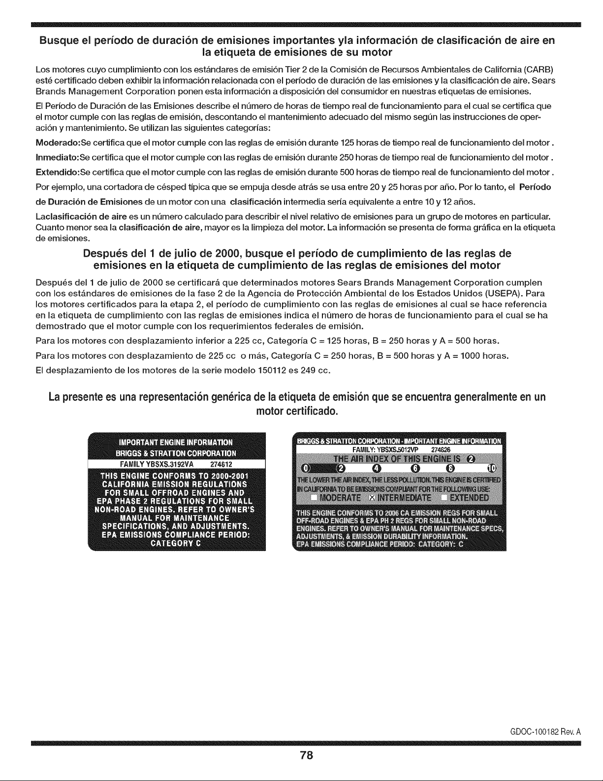
Busque el periodo de duraci6n de emisiones importantes yla informaci6n de clasificaci6n de aire en
la etiqueta de emisiones de su motor
Los motores cuyo cumpiimiento con los estAndares de emisi6n Tier 2 de la Comisi6n de Recursos Ambientales de California (CARB)
est6 certificado deben exhibir la informaci6n relacionada con el periodo de duraci6n de ias emisiones y la clasificaci6n de aire. Sears
Brands Management Corporation ponen esta informaci6n a disposici6n del consumidor en nuestras etiquetas de emisiones.
Ei Periodo de Duraci6n de las Emisiones describe el nQmero de horas de tiempo real de funcionamiento para el cuai se certifica que
el motor cumpie con ias reglas de emisi6n, descontando el mantenimiento adecuado del mismo segQn las instrucciones de oper-
aci6n y mantenimiento. Se utilizan las siguientes categonas:
Moderado:Se certifica que el motor cumpie con las reglas de emisi6n durante 125 horas de tiempo real de funcionamiento del motor.
Inmediato:Se certifica que el motor cumpie con las reglas de emisi6n durante 250 horas de tiempo real de funcionamiento del motor.
Extendido:Se certifica que el motor cumpie con las reglas de emisi6n durante 500 horas de tiempo real de funcionamiento del motor.
Por ejemplo, una cortadora de c6sped tJpica que se empuja desde arras se usa entre 20 y 25 horas por aSo. Por Io tanto, el Periodo
de Duraci6n de Emisiones de un motor con una clasificaci6n intermedia sena equivaiente a entre 10 y 12 aSos.
Laciasificaci6n de aire es un nQmero calculado para describir el nivel relativo de emisiones para un grupo de motores en particular.
Cuanto menor sea la clasificaci6n de aire, mayor es la limpieza del motor. La informaci6n se presenta de forma grAfica en la etiqueta
de emisiones.
Despu_s del 1 de julio de 2000, busque el periodo de cumplimiento de las reglas de
emisiones en la etiqueta de cumplimiento de las reglas de emisiones del motor
Despu6s del 1 de julio de 2000 se certificarA que determinados motores Sears Brands Management Corporation cumplen
con los estAndares de emisiones de la fase 2 de la Agencia de Protecci6n Ambientai de los Estados Unidos (USEPA). Para
los motores certificados para la etapa 2, el periodo de cumplimiento con ias reglas de emisiones al cual se hace referencia
en la etiqueta de cumplimiento con las reglas de emisiones indica el nQmero de horas de funcionamiento para el cual se ha
demostrado que el motor cumple con los requerimientos federales de emisi6n.
Para los motores con desplazamiento inferior a 225 cc, Categoria C = 125 horas, B = 250 horas y A = 500 horas.
Para los motores con desplazamiento de 225 cc o mAs, Categoria C = 250 horas, B = 500 horas y A = 1000 horas.
El desplazamiento de los motores de la serie modelo 150112 es 249 cc.
La presente es una representaci6n gen_rica de la etiqueta de emisi6n que se encuentra generaimente en un
motor certificado.
FAMILYYBSXS.3192VA 274812
GDOC-100182Rev.A
78
Felicitaciones por haber realizado una adquisici6n inteligente. El producto Craftsman® que ha
adquirido esta diseSado y fabricado para brindar muchos aSos de funcionamiento confiable. Pero
como todos los productos a veces puede requerir de reparaciones. Es en ese momento cuando el
disponer de un Acuerdo de protecci6n para reparaciones le puede ahorrar dinero y problemas.
A continuaci6n se detallan los puntos incluidos en el Acuerdo:
[] Servicio experto prestadopor nuestros 10,000 especialistas en reparaciones profesionales
[] Servicio ilirnitado sin cargo para las piezasy la mano de obra en todas las reparacionescubiertas
[] Reernplazo del producto hasta 1500 d61aressi no es posible reparar el producto cubierto
[] Descuento de 25% del precio normal del servicio y de las piezas relacionadas con el mismo que no esten cubiertas
por el acuerdo; ademas, 25% del precio normal de laverificaci6n de mantenimientopreventivo
[] Ayuda r_pida pot tel_fono - Io IlamamosResoluci6n RApida- el apoyo telef6nico de un Chamusca al representante.
Piense en nosotros como el manual "de un dueSohablador."
Una vez adquirido el Acuerdo, puede programar el servicio con tan s61orealizar una Ilamadatelef6nica. Puede Ilamar en
cualquier momento del dia o de la noche o programar un servicio en linea.
ElAcuerdo de Protecci6nde Reparaci6nes una compra sin riesgo. Si usted anula por alguna raz6n duranteel periodo de
garantia de producto, proporcionaremos un reembolso Ileno.O, un reembolso prorrateado en cualquier momento despues
del periodo de garantia de producto expira, iAdquiera hoy su acuerdode protecci6n para reparaciones!
Se aplican determinadas limitaciones y exclusiones. Para obtener informaciTn adicional y precios en los Estados
Unidos Ilame al 1-800-827-6655.
El *Coverage en Canad_ivaria en algunos articulos. Para detalles Ilenos la Ilamada Chamusca Canad_ien 1-800-
361-8885.
Servicio de instalaci6n de Sears
Si desea solicitar la instalaci6n profesionalde Sears de aparatos domesticos, dispositivos paraabrir portones, calentado-
res de agua y otros articulos domesticos importantes, en los Estados Unidos o Canada flame al 1-800-4-MY-HOME®.
79

Your Home
For troubleshooting, product manuals and expert advice:
managernylife
www.managemylife.com
For repair - in your home - of all major brand appliances,
lawn and garden equipment, or heating and cooling systems,
no matter who made it, no matter who sold it!
For the replacement parts, accessories and
owner's manuals that you need to do-it-yourself.
For Sears professional installation of home appliances
and items like garage door openers and water heaters.
1-800-4-MY-HOME ® (1-800-469-4663)
Call anytime, day or night (U.S.A. and Canada)
www.sears.com www.sears.ca
Our Home
For repair of carry-in items like vacuums, lawn equipment,
and electronics, call anytime for the location of your nearest
Sears Parts & Repair Service Center
1-800-488-1222 (U.S.A.) 1-800-469-4663 (Canada)
www.sears.com www.sears.ca
To purchase a protection agreement on a product serviced by Sears:
1-800-827-6655 (U.S.A.) 1-800-361-6665 (Canada)
Para pedir servicio de reparaci6n
a domicilio, y para ordenar piezas:
1-888-SU-HOGAR ®
(1-888-784-6427)
www.sears.com
Au Canada pour service en frangais:
1-800-LE-FOYER Mc
(1-800-533-6937)
www.sears.ca
® Registered Trademark / TMTrademark of KCD IP, LLC in the United States, or Sears Brands, LLC in other countries
® Marca Registrada ! TMMarca de Fabrica de KCD IP, LLC en Estados Unidos, o Sears Brands, LLC in otros paises
MCMarque de commerce ! MDMarque deposee de Sears Brands, LLC


