Loading ...
Loading ...
Loading ...
• Push down on the shift rod (and shift arm assem-
bly) as far as it will go. Hold it in this position.
• Thread the ferrule up or down the shift rod as
necessary until the ferrule lines up with the upper
hole in the shift lever. Refer to figure 9.
• Insert ferrule into the upper hole in the shift lever
from the right side when adjustment is correct.
Secure with flat washer and hairpin clip.
• Before operating the snow thrower, check for cor-
rect adjustment of the traction drive control as in-
structed inthe Final Adjustment section.
CARBURETOR
WARNING: If any adjustments are made to
the engine while the engine is running (e.g.
carburetor), keep clear of all moving parts.
Be careful of heated surfaces and muffler.
If you think your carburetor needs adjusting,
see your nearest authorized Tecumseh
Service Outlet.
SHAVE PLATE AND SKID SHOES
The shave plate and skid shoes on the bottom of the
snow thrower are subject to wear. They should be
checked periodically and replaced when necessary.
• To remove skid shoes, remove the four carriage
bolts, belleville washers and hex nuts which attach
them to the snow thrower.
• Reassemble new skid shoes with the four carriage
bolts, belleville washers (cupped side goes against
skid shoes) and hex nuts. Make certain the skid
shoes are adjusted to be level.
• To remove shave plate, remove the carriage bolts,
belleville washers and hex nuts which attach it to
the snow thrower housing. Reassemble new
shave plate, making sure heads of the carriage
bolts are to the inside of the housing. Tighten
securely.
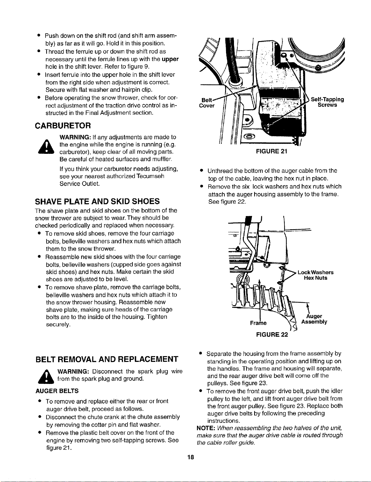
Self-Tapping
Cover Screws
/
FIGURE 21
• Unthread the bottom of the auger cable from the
top of the cable, leaving the hex nut in place.
• Remove the six lock washers and hex nuts which
attach the auger housing assembly to the frame.
See figure 22.
pLockWashers
Hex Nuts
Frame
FIGURE 22
Auger
Assembly
BELT REMOVAL AND REPLACEMENT
,_ WARNING: Disconnect the spark plug wire
from the spark plug and ground.
AUGER BELTS
• To remove and replace either the rear or front
auger drive belt, proceed as follows.
• Disconnect the chute crank at the chute assembly
by removing the cotter pin and flat washer.
• Remove the plastic belt cover on the front of the
engine by removing two self-tapping screws. See
figure 21.
• Separate the housing from the frame assembly by
standing in the operating position and lifting up on
the handles. The frame and housing will separate,
and the rear auger drive belt will come off the
pulleys. See figure 23.
• To remove the front auger drive belt, push the idler
pulley to the left, and lift front auger drive belt from
the front auger pulley. See figure 23. Replace both
auger drive belts by following the preceding
instructions.
NOTE: When reassembling the two halves of the unit,
make sure that the auger drive cable is routed through
the cable roller guide.
18
Loading ...
Loading ...
Loading ...