Loading ...
Loading ...
Loading ...
The operation of any snow thrower can result in foreign objects being thrown into the eyes, which
can result in severe eye damage. Always wear safety glasses or eye shields while operating the
snow thrower or performing any adjustments or repairs. We recommend standard safety glasses
or wide vision safety mask for over your glasses available at SEARS retail stores.
OPERATION CONTROLS
CHUTE CRANK
The chute crank is located on left hand side of the
snow thrower. See figure 13.To change the direction in
which snow is thrown, turn chute crank as follows: turn
clockwise to discharge to the left; turn counterclock-
wise to discharge to the right.
THROTTLE CONTROL
The throttle control is located on the engine. It
regulates the speed of the engine. See figure 14.
SAFETY IGNITION SWITCH
The ignition key must be inserted into the switch for
the unit to start. Remove the ignition key when snow
thrower is not in use. See figure 14.
LEFT AND RIGHT TURN TRIGGER
The left and right turn triggers are located on the
underside of the handles and are used to assist in
steering your snow thrower. See figure 15. Squeeze
the right turn trigger when turning right, squeeze the
left turn trigger when turning left. Operate your snow
thrower in open areas until you become familiar with
these controls.
SHIFT LEVER
The shift lever is located in the center of the handle
panel. The shift lever may be moved into one of eight
positions. Use the shift lever to determine ground
speed. Forward---one of six speeds; position one (1) is
the slowest and position six (6) isthe fastest.
Reverse--two reverse (R) speeds; R2 is faster.
AUGER CONTROL
The auger control is located on the left handle. See
figure 15. Squeeze the auger control against the
handle to engage the augers; release to disengage
the augers. (Traction drive control must also be
released.)
TRACTION DRIVE CONTROL
The traction drive control is located on the right han-
dle. Squeeze the traction drive control to engage the
track drive; release to stop. See figure 15.
This same lever also locks the auger control so
you can turn the chute crank without interrupting
the snow throwing process. If the auger control is
engaged with the traction drive control engaged, you
can release the auger control (on the left handle) and
the augers will remain engaged. Release the traction
drive control to stop both the augers and wheel drive.
(Auger control must also be released).
CHUTE DISTANCE CONTROL
The distance snow is thrown can be adjusted by
adjusting the angle of the chute assembly. Move the
chute distance control forward to decrease the dis-
tance, toward the rear to increase the distance. See
figure 15.
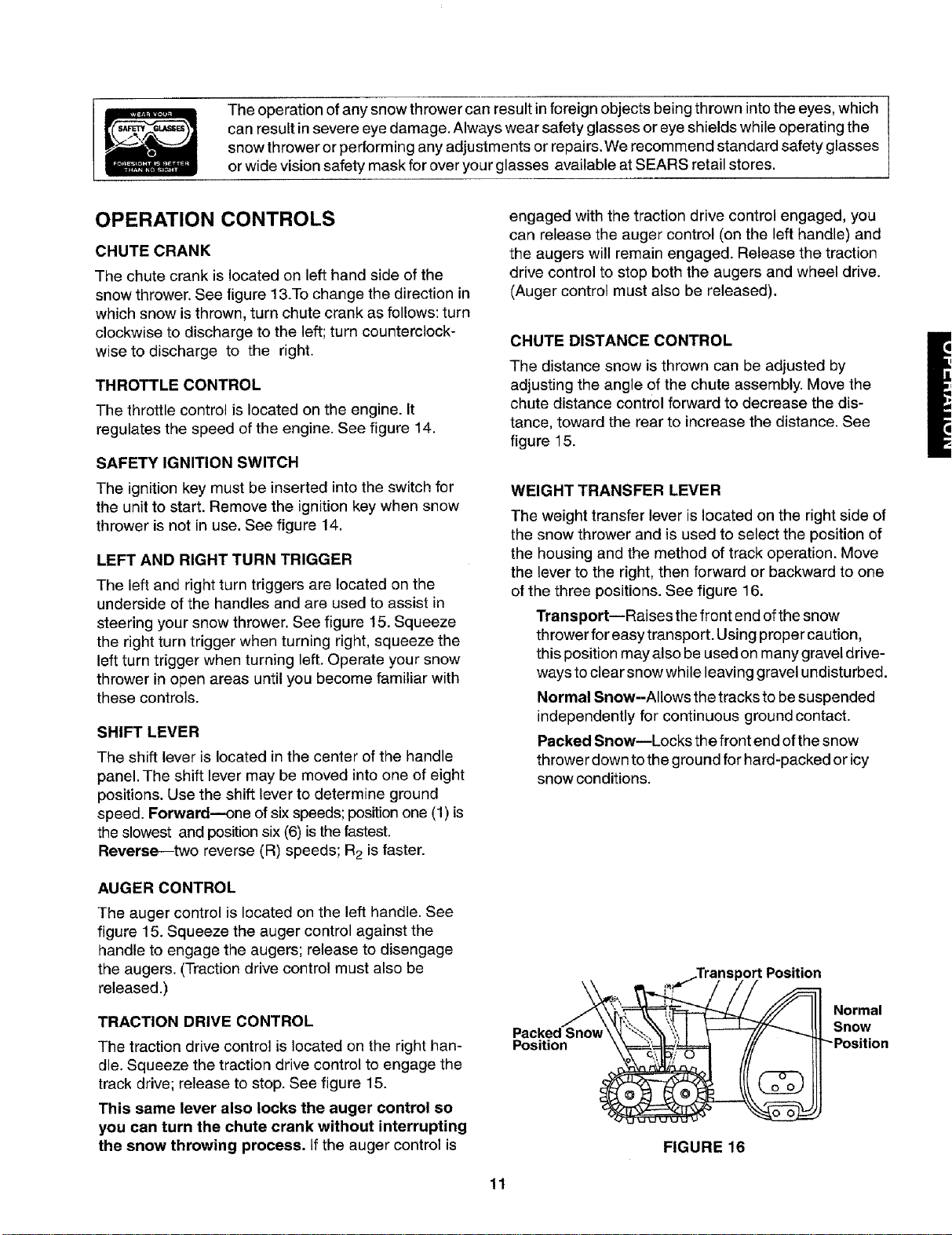
WEIGHT TRANSFER LEVER
The weight transfer lever is located on the right side of
the snow thrower and is used to select the position of
the housing and the method of track operation. Move
the lever to the right, then forward or backward to one
of the three positions. See figure 16.
Transport--Raises the front end of the snow
thrower for easy transport. Using proper caution,
this position may also be used on many gravel drive-
ways to clear snow while leaving gravel undisturbed.
Normal Snow--Allows the tracks to be suspended
independently for continuous ground contact.
Packed Snow--Locks the front end of the snow
thrower down to the ground for hard-packed or icy
snow conditions.
Position
Position
Normal
Snow
FIGURE 16
11
Loading ...
Loading ...
Loading ...