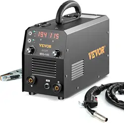
IGBT INVERTER MIG WELDER
USER'S MANUAL
MIG-1KG Series
MIG-DS Series
MIG-5KG-A Series
MIG-5KG-B Series
NOTE: Please read this manual carefully before use.

Safety Caution!
On the process of welding, there will be any possibility of injury, so please take
protection into consideration during operation. More details please review the
Operator Safety Guide, which complies with the preventive requirements of the
manufacturer
Electric shock——may lead to death !!
·Set the earth fitting according to applying standard.
·It is forbidden to touch the electric parts and electrode when the skin is naked, wearing wet
gloves or clothes.
·Make sure you are insulated from the ground and the workshop.
·Make sure you are in safe position.
Gas——may be harmful to health!
·Keep your head out of the gas.
·When arc welding, air extractor should be used to prevent from breathing gas.
Arc radiation——Harmful to your eye and burn your skin.
·Use suitable helmet and light filter, wear protective garment to protect eye and body.
·Use suitable helmet or curtain to protect looker-on.
Fire
·Welding spark may cause fire, make sure the welding area no tinder around.
Noise——extreme noise harmful to ear.
·Use ear protector or others means to protect ear.
·Warn that noise harmful to hearing if looker-on around.
Malfunction——When trouble, count on the professionals
·If trouble in installation and operation, please follow this manual instruction to check up.
·If fail to fully understand the manual, or fail to solve the problem with the instruction, you should
contact the suppliers or our service center for professional help.
About the machine
The welding machine is adopting the most advanced inverter technology, suitable for gas welding
(solid wire) and gasless welding (Flux-cored wire).
The development of inverter welding equipment profits from the development of the inverter power
supply theory and components. Inverter welding power source utilizes high-power component IGBT to
transfer 50/60HZ frequency up to 60KHz, then reduce the voltage and commutate, and output
high-power voltage via PWM technology. Because of the great reduce of the main transformer’s weight
and volume; the efficiency increases by 30%. The appearance of inverter welding equipment is
considered to be a revolution for welding industry.
Inside of the machine is equipped with electronic reactor circuit which can accurately control the
process of the electric short transition and blending transition and result excellent welding characteristic.
Comparing with synergic welding machine and other machine, it has the following advantages: stable
wire speed, compact, power saving, no electromagnetic noise. Continuous and stable operation with
small current, especially suitable for welding sheet of low-carbon steel, alloyed steel and stainless steel.
Automatic voltage pulsation compensation capability, small sparkle, good arcing, uniform welding
pool, high duty cycle and so on.
Thanks for purchasing product and hope for your precious advice. We will dedicate to produce the
best products and offer the best service.
CAUTION!
The machine is mainly used in industry. It will produce radio wave, so the worker should make
fully preparation for protection.

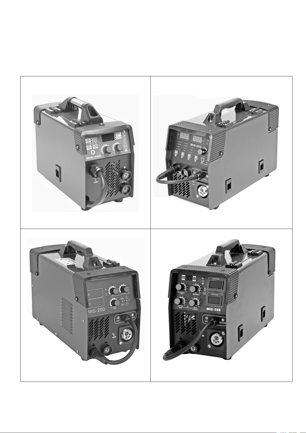
PARAMETERS
Model
MIG-160
MIG-200
MIG-250
MIG-270
Input Voltage.(V)
1 Phase
230V15%
1 Phase
230V15%
1 Phase
230V15%
1 Phase
230V15%
Input Voltage.(V)
1 Phase
AC110/220V
1 Phase
AC110/220V
1 Phase
AC110/220V
1 Phase
AC110/220V
Frequency(HZ)
50/60
50/60
50/60
50/60
Rated input current(A)
220V
20.2
27.6
38.0
38.0
Rated input current(A)
110V
34
37
41.1
43.1
Output current (A)
220V
40-160
40-200
40-250
40-270
Output current (A)
110V
30-120
30-130
40-140
40-150
No-load Voltage
(V)
16.5-22.0
16.5-23.0
16.5-24.0
16.5-25.5
(25℃)Duty cycle(%)
60%
60%
60%
60%
Power factor
0.93
0.93
0.93
0.93
Efficiency(%)
85
85
85
85
Wire Feeder
Inside
Inside
Inside
Inside
Wire speed(m / min)
2.5-15
2.5-14
2.5-14
2.5-14
Wire speed(m / min)
110V
2.5-10
3-8
3-8
3-8
Wire diameter(mm)
0.6/0.8/0.9
0.8/0.9/1.0
0.8/0.9/1.0
0.8/0.9/1.0
Protection Degree
IP21S
IP21S
IP21S
IP21S
Insulation Class
F
F
F
F
Suitable thickness(mm)
0.8above
0.8above
0.8above
0.8above
Weight (kg)
13.0
14.0
14.5
14.5
Dimension (mm)
520×300×370
520×300×370
520×300×370
520×300×370

MIG-DS SERIES PANEL INTRODUCTION
○
1, MIG Welding Voltage Display ○
2, Welding Current Display
○3, to adjust parameter,Quick wire extension function to press button. ○4, choose different
functions.○5, welding voltage and current. ○6, Welding Wire Diameter. ○7,MIG welding material
and shielding gas. ○8,Welding Method. ○9, Polarity Conversion Cable Connector,
Note: VERY IMPORTANT!
A), When use gas welding (solid wire), Install ○
9into ○
11 , and install earth clamp with
cable into○
12 . B), When use gasless welding (Flux wire), Install ○
9into ○
12 , and install
earth clamp with cable into○
11 .
○
10 ,MIG Welding Torch ○
11 ,ositive Polarity Connector (+) ○
12 ,Negative Polarity Connector(-)
○
13 , Parameter Table ○
14 , Power Switch for ON/OFF. ○
15 , Gas Hose Inlet Connector○
16 ,
Power Cable with Plug.○
17 , Ground Nut. ○
18 built-in cooling fan and ventilation.
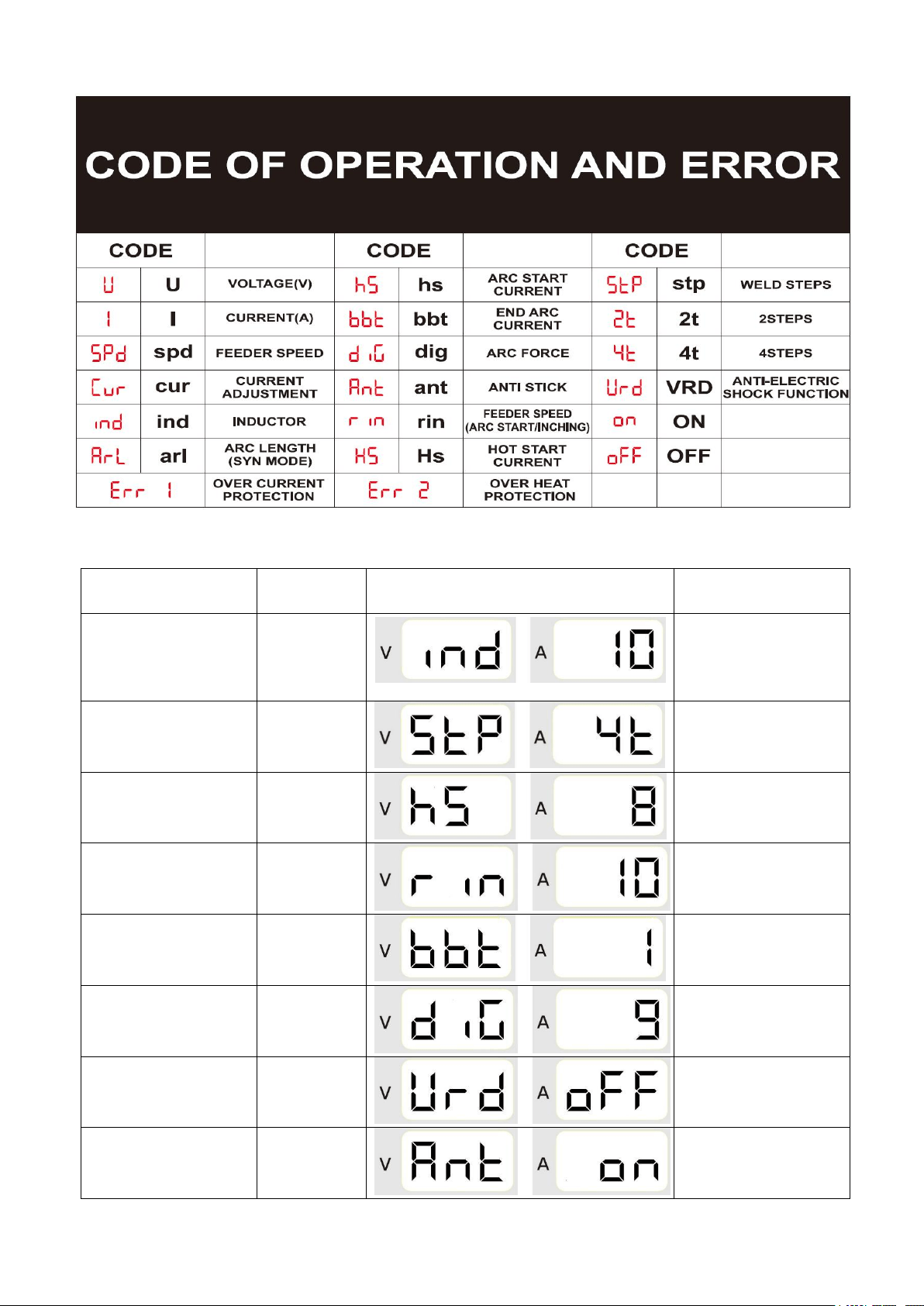
Function Code
Parameter
rangee
Symbol
Welding Method
Ind = Inductance
-10 ~ +10%
SPL MIG & SYN MIG
stp = Step for Torch
control mode
2T/4T
SPL MIG & SYN MIG
hs = hot start
0 ~10A
SPL MIG & SYN MIG&
MMA
rin = arc-start speed
0 ~10ms
SPL MIG & SYN MIG
bbt = burnback
0 ~1s
SPL MIG & SYN MIG
dIG = Arc Force
0-10A
MMA
Vrd = Voltage
Reduction Device
On/Off
MMA
Ant = Anti-stick
On/Off
MMA

MIG-S2 SERIES PANEL INTRODUCTION
○
1 , Over-Heat Alarm ○
2 , Power Indicator ○
3 ,Welding Current Display
○
4, MIG Welding Voltage Display ○
5, Switch for mode of MMA/LIFT-TIG/MIG
○
6 , Welding Wire Inching ○
7 , MMA Welding Current Adjustment
○
8 , MIG Burnback Function ○
9 , MIG Voltage Adjustment ○
10 ,MIG Wire Speed Adjustment
○
11 , Polarity Conversion Cable Connector,
Note: VERY IMPORTANT!
A), When use gas welding (solid wire), Install ○
11 into ○
12 , and install earth clamp with
cable into○
13 .
A), When use gasless welding (Flux wire), Install ○
11 into ○
13 , and install earth clamp
with cable into○
12 .
○
12 , Positive Polarity Connector (+) ○
13 , Negative Polarity Connector(-)
○
14 , MIG Welding Torch ○
15 , Power Switch for ON/OFF. ○
16 , Gas Hose Inlet Connector
○
17 , Power Cable with Plug.○
18 , Ground Nut. ○
19 built-in cooling fan and ventilation.

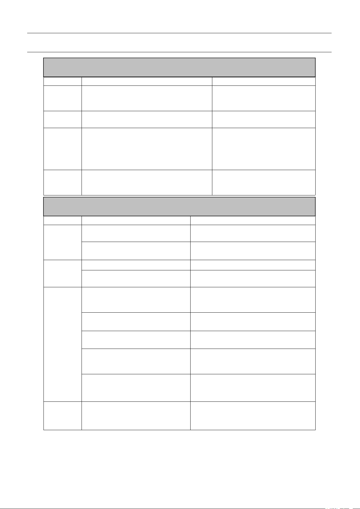
Description for various functions
Item
Note
Over-Heat Alarm
When temperature of the machine is too high, this
indicator will light and machine stop working.
Power Indicator
/
Welding Current Display
While arc is struck (welding) displays actual welding
current.
MIG Welding Voltage Display
While MIG mode display actual welding voltage.
Switch for mode of
MMA/LIFT-TIG/MIG
Three kinds of welding models can be choose when turn to
different position.
Welding Wire Inching
It can let welding wire reach contact tips in fast speed.
MMA Welding Current Adjustment
While MMA mode can adjust welding current from small to
big
MIG Burnback Function
It can remove small ball after stopping welding
MIG Voltage Adjustment
While MIG mode can adjust voltage from low to high.
MIG Wire Speed Adjustment
stepless adjusment from slow to fast.
Polarity Conversion Cable
Connector
When gas welding (solid wire),install this into Positive
Polarity Connector (+)
When gasless welding (Flux wire),install this into Negative
Polarity Connector(-)
Positive Polarity Connector (+)
/
Negative Polarity Connector(-)
/
MIG Welding Torch
Integrated MIG TORCH or Binzel MIG Torch
Power Switch for ON/OFF
Gas Hose Inlet Connector
When use gas welding (solid welding wire), install gas
hose into this connector.
Power Cable with Plug
/
Ground Nut
/
built-in cooling fan and ventilation
/

Installment
The welding equipment is equipped with power voltage compensation set. When power voltage
changes between±15% of rated voltage, it still works normally.
When using long cable, in order to minimize the reduce of voltage, big cable is suggested. If the
cable is too long, it will affect the performance of arcing and other system function, so stated length is
suggested.
1、Make sure the intake of the machine is not covered or blocked to prevent the malfunction of the
cooling system.
2、Use earth cable that the section no less than 6mm2to connect the housing and earth, the method is
from the connection in the back of the machine to the earth set, or make sure the earth end of power
switch reaches the earth. Both ways can be used for better security.
Installment ,when use gas welding (solid wire):
1) Connect the gas bottle with CO2regulator flow meter and the Input Gas Connector behind the
machine via gas hose.
2) Insert the cable connector of earth cable into the socket in the front panel.
3) Set the welding wire spool on the wheel axis, the wheel hole should be matched with the wheel
fixer.
4) Choose wire slot according to wire size.
5) Loosen the screw of wire-pressing wheel, put the wire into slot via wire-lead tube, tune the
Wire-pressing wheel to fix wire from gliding, but pressure should be suitable in case the wire distorts
and affects wire sending.
6) Wire roller should turn clockwise rotation to let out wire, to prevent wire from gliding; wire is
usually set to the fixed hole on the wheel side. To prevent the bent wire from getting stuck, please cut off
this part of the wire.
7) The MIG torch has been settled inside of the machine just need put the wire into the torch by hand.
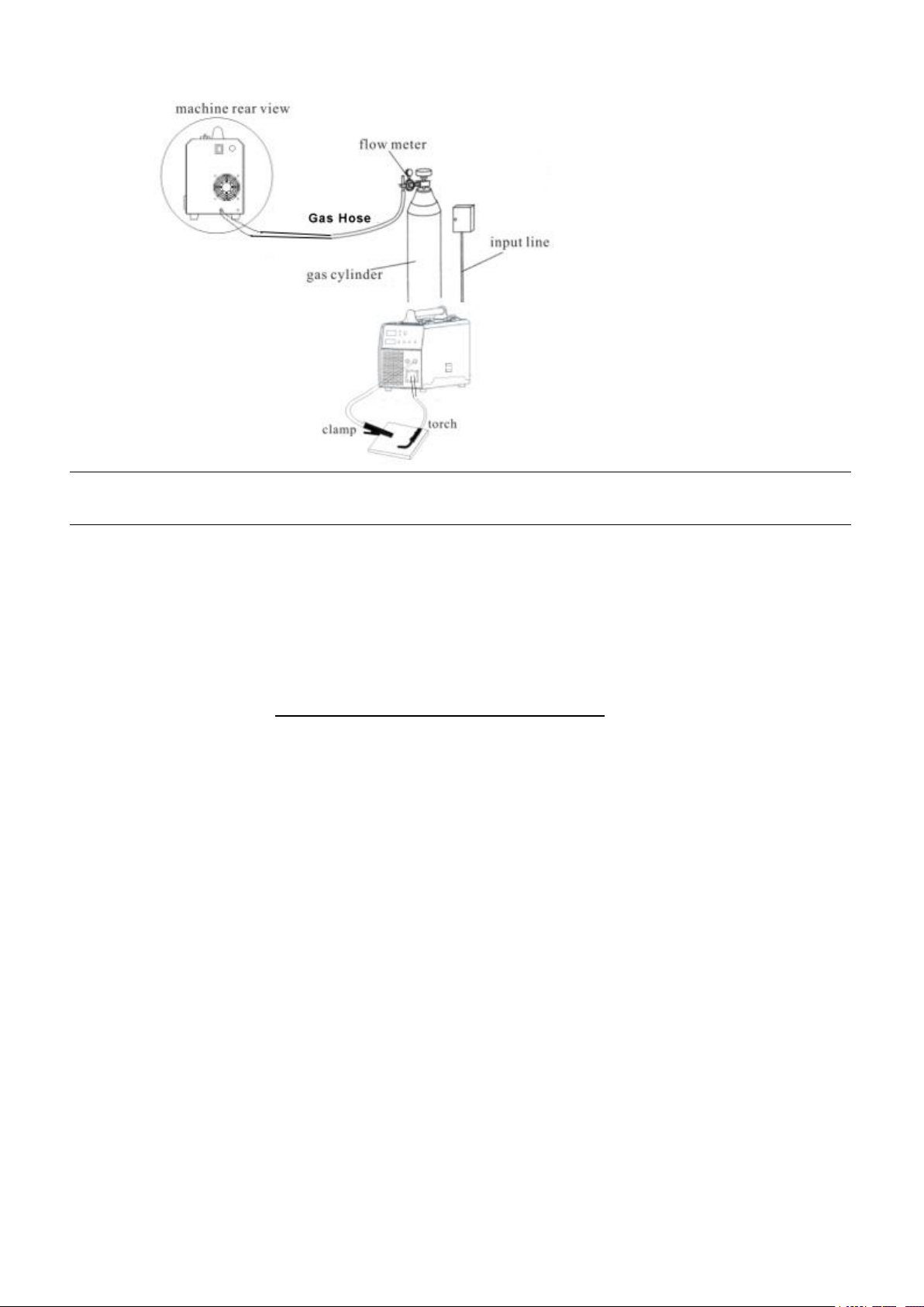
Operation
1、Put the power switch to “ON” position, open the valve of CO2 cylinder and adjust the flow.
2、Choose suitable welding contact tips based on wire diameter.
3、Tune the voltage switch, speed switch to the right position based on the thickness of the work piece
and mechanics.
4、Press the torch switch to let out the wire to the torch head and begin to work.
Installment ,when use gasless welding (Flux-cored wire):
1) Insert the cable connector of earth cable into the socket in the front panel.
2) Set the welding wire spool on the wheel axis, the wheel hole should be matched with the wheel
fixer.
3) Choose wire slot according to wire size.
4) Loosen the screw of wire-pressing wheel, put the wire into slot via wire-lead tube, tune the
Wire-pressing wheel to fix wire from gliding, but pressure should be suitable in case the wire distorts
and affects wire sending.
5) Wire roller should turn clockwise rotation to let out wire, to prevent wire from gliding; wire is
usually set to the fixed hole on the wheel side. To prevent the bent wire from getting stuck, please cut off
this part of the wire.
6) The MIG torch has been settled inside of the machine just need put the wire into the torch by hand.

NOTES OR PREVENTIVE MEASURES
1、Environment
1)The machine can perform in environment where conditions are dry with a dampness lever of max
90%.
2)Ambient temperature is between 10 to 40 degrees centigrade.
3)Avoid welding in sunshine or drippings.
4)Do not use the machine in environment where condition is polluted with conductive dust on the air
or corrosiveness gas on the air.
5)Avoid gas welding in the environment of strong airflow.
2、Safety norms
The welding machine has installed protection circuit of over voltage and current and heat. When
voltage and output current and temperature of machine are exceeding the rate standard, welding
machine will stop working automatically. Because that will be damage to welding machine, user
must pay attention as following.
1)The working area is adequately ventilated!
The welding machine is powerful machine, when it is being operated, it generated by high currents,
and natural wind will not satisfy machine cool demands. So there is a fan in inter-machine to cool
down machine. Make sure the intake is not in block or covered, it is 0.3 meter from welding machine
to objects of environment. User should make sure the working area is adequately ventilated. It is
important for the performance and the longevity of the machine.
2)Do not over load!
The operator should remember to watch the max duty current (Response to the selected duty cycle).
Keep welding current is not exceed max duty cycle current.
Over-load current will damage and burn up machine.
3)No over voltage!
Power voltage can be found in diagram of main technical data. Automatic compensation circuit of
voltage will assure that welding current keep in allowable arrangement. If power voltage is
exceeding allowance arrangement limited, it is damaged to components of machine. The operator
should understand the situation and take preventive measures.
4)There is a grounding screw behind welding machine, there is grounding marker on it Mantle must
be grounded reliable with cable which section is over 6 square millimeter I order to prevent from
static electricity and leaking.
5)If welding time is exceeded duty cycle limited, welding machine will stop working
for protection. Because machine is overheated, temperature control switch is on
“ON’’ position and the indicator light is red. In this situation, you don’t have to
pull the plug, in order to let the fan cool the machine. When the indicator light is
off, and the temperature goes down to the standard range, it can weld again.
QUESTIONS IS BE RUN INTO IN WELDING
Fittings, welding materials, environment factor, supply powers maybe have something to do with
welding. User must try to improve welding environment.
A、Arcing-striking is difficult and easy to pause:
1) Make sure the earth cable clincher connects the work piece well.
2) Check each connecting point connected or not.
B、Output current can not reach rated volume:
That supplied voltage is different from the rated will lead to unconformity of the output current and
the adjusted current. When Supplied voltage lower than the rated, the max output current will be lower
than the rated.
C、Current is not stabilizing when machine is been operating.
It has something with factors as following:
1) Electric wire net voltage has been changed;
2) There is harmful interference from electric wire net or other equipment。
D Welding gap has air hole.
1) Check the gas supply loop leaks or not.
2) Surface of mother material has oil, stain, rust, lacquer or other impurity.
MAINTENANCE
CAUTION:
Before Maintenance and checking, power must be turned off, and before
Opening the housing, make sure the power plug is pulled off..
1 、 Remove dust by dry and clean compressed air regularly, if welding machine is operating in
environment where is polluted with smokes and pollution air, the machine need remove dust
everyday.
2、Pressure of compressed air must be inside the reasonable arrangement in order to prevent damaging
to small components of inter-machine.
3、Check inter circuit of welding machine regularly and make sure the cable
Circuit is connected correctly and connectors are connected tightly (especially insert connector and
components). If scale and loose are found, please give a good polish to them, then connect them
again tightly.
4、Avoid water and steam enter into inter-machine, if them enter into machine,
Please dry inter-machine then check insulation of machine.
5、If welding machine will not be operated long time, it must be put into packing
Box And store in dry environment.
6、When wire machine operates for every 300 hours, the electric carbon brush and
armature rectifier should be polished, the reducer should be cleaned, and
lubricator should be added to the turbo and bearing.
CHECK FAULT
Notes: If user wants to operate machine as following, the operator must be a personnel in a specific
field of electricity and safety and hold the relevant
certificate that proves their ability and knowledge. Before maintenance, contact
with our sale agent for authorization is suggested.
Faults
Resolvable Method
Power indicator
is not lit, fan
does not work
and no welding
output
1、Make sure air switch is closed.
2、Check if electric wire net is in work.
3、Some of heat-variable resistors(four) of power panel is
Damaged, when it happen, general DC24v relay is open or
Connectors are poor contact.
4、Power panel(bottom board) is damaged, DC 310V voltage
Cannot be output.
(1) Silicon bridge is broken or connector of silicon bridge
Poor contact.
(2) Power panel has been burned up.
(3) Check the wire from the power switch to input cable is poor
contact or not
5、Auxiliary power of control panel is in fault.
Power indicator
is lit, fan works,
no welding
output
1、Check if all kinds of cables of inter-machine are poor contact.
2、Output connector is cut off or poor contacted.
3、Control cable or switch of torch is broken.
4、Control circuit is broken.
Power indicator
is lit, fan works,
abnormal
indicator is lit.
1、Maybe it is overheated protection, please turn off machine first,
then turn on the machine again after abnormal indicator is off.
2、Maybe it is overheated protection, wait for 2-3 minutes.
3、Maybe inverter circuit is in fault:
(1) If abnormal indicator is still lit, some of IGBT is damaged on the
main board, find out and replace it with same model.
(2) If abnormal indicator is not lit,:
a. Maybe transformer is damaged, measure inductance volume
and Q volume of main transformer by inductance bridge.
b. Maybe secondary rectifier tube of transformer is damaged, find
out faults and replace rectifier tube with it.
Note: The
The operations
operations below
below require
require the
the operator
operator with
with enough
enough knowledge
knowledge of
of electricity
electricity and
and overall
overall
common
common sense
sense of
of security
security,
,qualification
qualification certificate
certificate which
which can
can proof
proof their
their ability
ability and
and knowledge
knowledge is
is a
a
necessary.
necessary. Before
Before the
the inspection,
inspection, we
we recommend
recommend that
that you
you should
should contact
contact with
with us
us and
and get
get approval
approval from
from
them.
them.
i
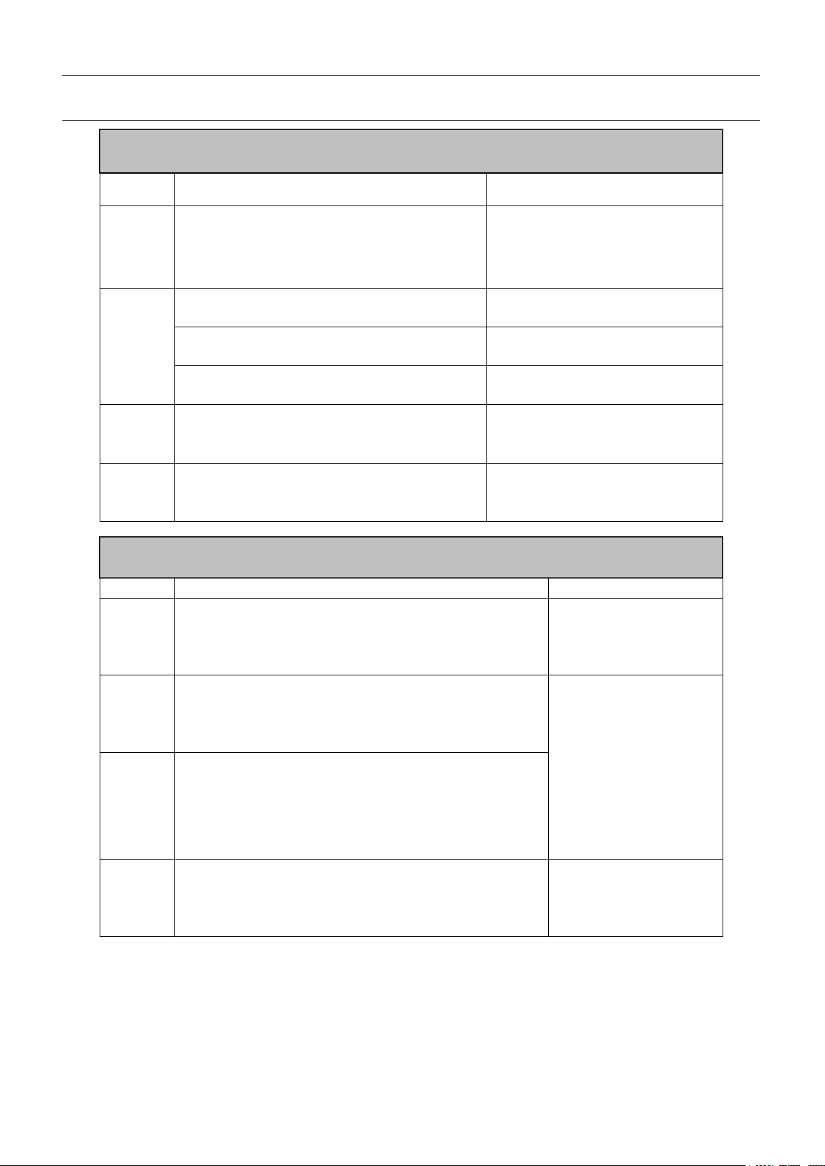
CHECK FAULTS
When abnormal situation such as failure of welding, unstable arc, poor welding result, do not
consider that it must be some faults.
The machine may be well but just some reasons cause abnormality such as that some connectors
are loosened, forget to turn on the switch, wrong setting, broken cable and gas pipe, etc. So before
maintenance, Please check it up first, some problem may be solved.
The following is earlier checking diagram by this way. In the top right corner item you can find the
problem, please check according to the diagram for the one with “O” mark.
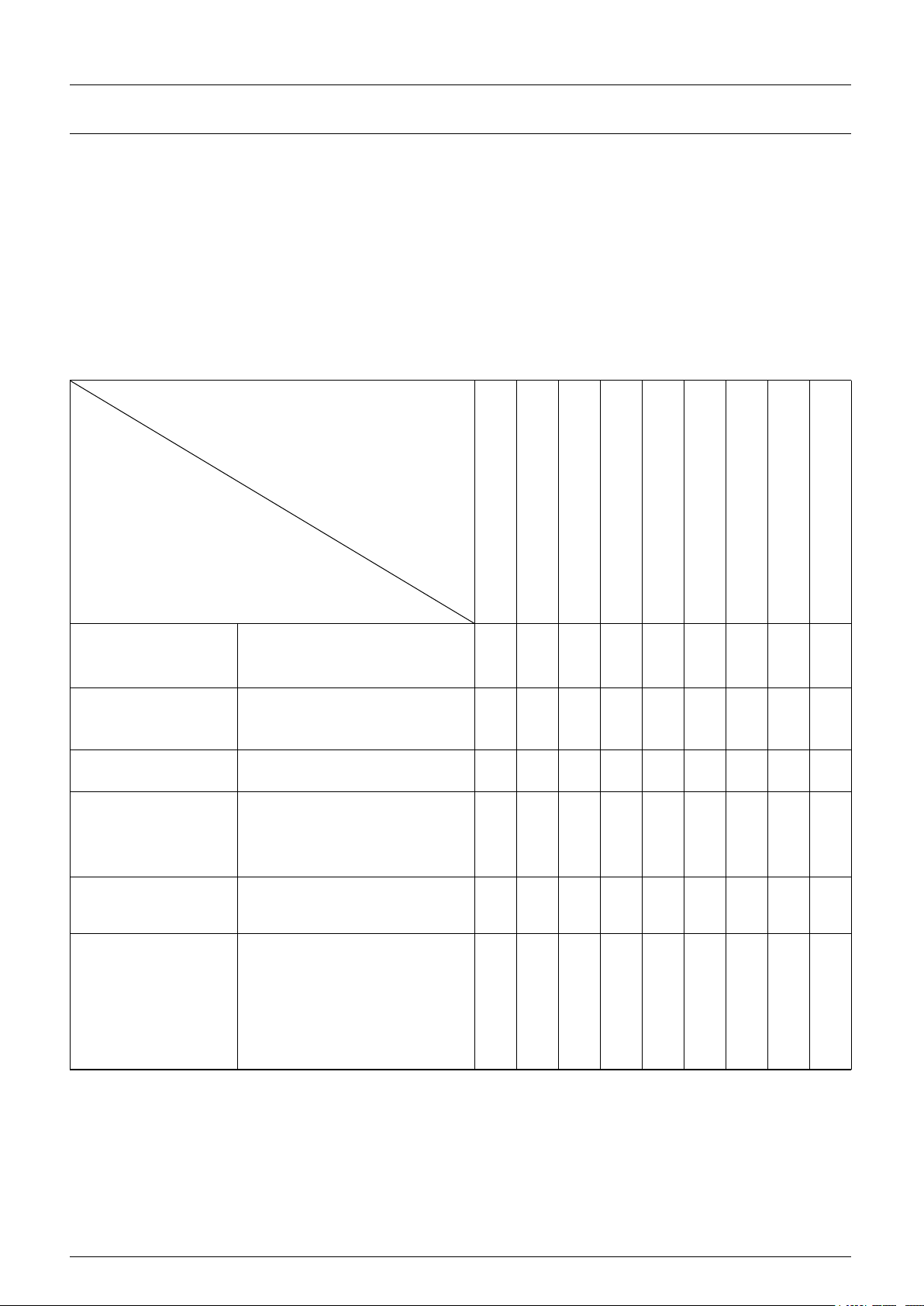
EARLIER CHECKING DIAGRAM FOR THE ABNORMAL
The abnormal
Place and item to be checked
No arcing
No gas
Can not Send wire
Poor Arcing initiation
Unstable arc
Welding margin unclean
Wire and Material conglutinated
Wire links Electric leading hole
fcon conglutinated
Have air hole
Power supply box
(input protective
set )
1、connected or not
2、fuse broken
3、connector loosen
〇
〇
〇
〇
〇
〇
Input cable
1、Broken or not
2、Connector loosen
3、overheat
〇
〇
〇
〇
〇
〇
Power
1、Switched or not
2、lack phase
〇
〇
〇
〇
〇
〇
〇
〇
Gas cylinder&adjuster
1、open cover
2、remains of gas
3、flow setting volume
4、Connecting point loosen
〇
〇
Gas pipe (access from
the high-pressure
cylinder to torch)
1、Connecting point loosen
2、Pipe broken
〇
Wire sending
equipment
1、Wheel and leading tube not
match
2、Wheel broken, slot blocked
or lack
3、Over pressing or loosen,
powder store up in entrance
of SUS tube
〇
〇
〇
〇
〇
DAILY CHECKING
Position
Checking keys
Remarks
Control
panel
1.switch condition of operation, transfer
and installment.
2.test the power indicator
Cooling
fan
1.check if there is wind and the sound
normal or not.
If abnormal noise and no wind,
to check the inner.
Power
part
1.when electrified, abnormal smell or not.
2.when electrified, abnormal vibration and
buzz or not.
3.color changing and heating or not in
appearance.
Periphery
1.gas pipe broken, loosen or not.
2.housing and other fixed parts loosen or
not.
Position
Checking keys
Remarks
Loophole
1.If installment fixed, the front
distorted
Reason for air hole.
2.attach splash or not.
Reason for burning the torch.
(can use splash-proof material )
Electric
hole
1.If installment fixed
Reason of torch screw thread damage
2.damage of its head and hole
blocked nor not
Reason of unstable arc and broken arc
Wire
sending
tube
1.check the extended size of the
pipe
Have to be changed when less than
6mm, when the extended part too small,
the arc will be unstable.
2.wire diameter and the tube inner
diameter match or not
Reason of unstable arc, please use the
suitable tube.
3.partial winding and extended
Reason of poor wires sending and
unstable arc, please change.
4.block caused by dirt in the tube,
and the remains of the wire
plating lay.
Reason of poor wire sending and
unstable arc, (use kerosene to wipe or
change new one.)
5.wire sending tube broken
O circle wear out
1.Pyrocondensation tube broken, change
new tube
2.Change new O circle
Gas
bypass
Forget to insert or the hole
blocked, or different factory
component.
May lead to vice (splash) because of
poor gas shield, torch body get burned
(arc in the torch), please handle.
WELDING TORCH
WELDING POWER SUPPLY
DAILY CHECK
Position
Checking keys
Remarks
Pressing
arm
1.If put the arm to the suitable indicating
level.
(notes:not to damage wire less than
Ф1.0mm )
Lead to unstable arc and wire
sending.
Wire
Lead
Tube
1.If powder or residue store up in the mouth
of the tube.
Clean the residue and check the
reason and solve it.
2.Wire diameter and the tube inner diameter
match or not
If not match, lead to unstable arc
and residue.
3.If the tube mouth center matches the wire
wheel slot center or not.
If unmatched, lead to unstable
arc and residue.
Wire
wheel
1.Wire diameter matches the wheel’s
requirement
2.If the wheel slot blocked
1.Lead to unstable arc and
residue, and block wire tube.
2.Change new one if necessary
Pressure
wheel
Check the stability of its move, and
wearing-out of pressed wire, the narrowing
of its contact surface
Lead to unstable arc and wire
sending.
Position
Checking keys
Remarks
Torch
cable
1.If torch cable over bended.
2.If the metal connecting point of mobile plug loosen
1. Cause poor wire
sending
2.Unstable arc if cable
over bended.
Output
cable
1. Wearing-out of the cable insulated material.
2.Cable connecting head naked (insulation damage),
or loosen (the end of power supply, and cable of
main material connecting point.)
For life security and
stable welding, adopt
suitable method to
check according to
working place.
Simple check daily
Careful and
in-depth check on
fixed period
Input
cable
1.If the connect of power supply input, protective
equipment input and the output end fixed or not.
2.If the security equipment cable reliably connected.
3.If the power input end cable fixed
4.If the input cable is worn out and bares the conductor.
Earth
cable
1.If the earth cable that connects the power supply is
broken and connect tightly.
2.If the earth cable that connects the main part is
broken and connects tightly.
To prevent creep age
and insure security,
please make daily
check.
CABLE
WIRE FEEDER