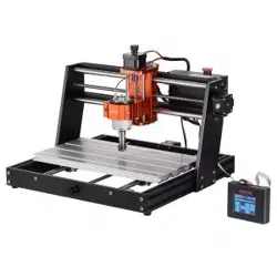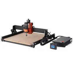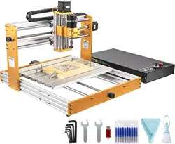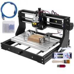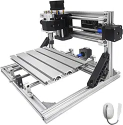

2418
CNC Engraving Machine
12
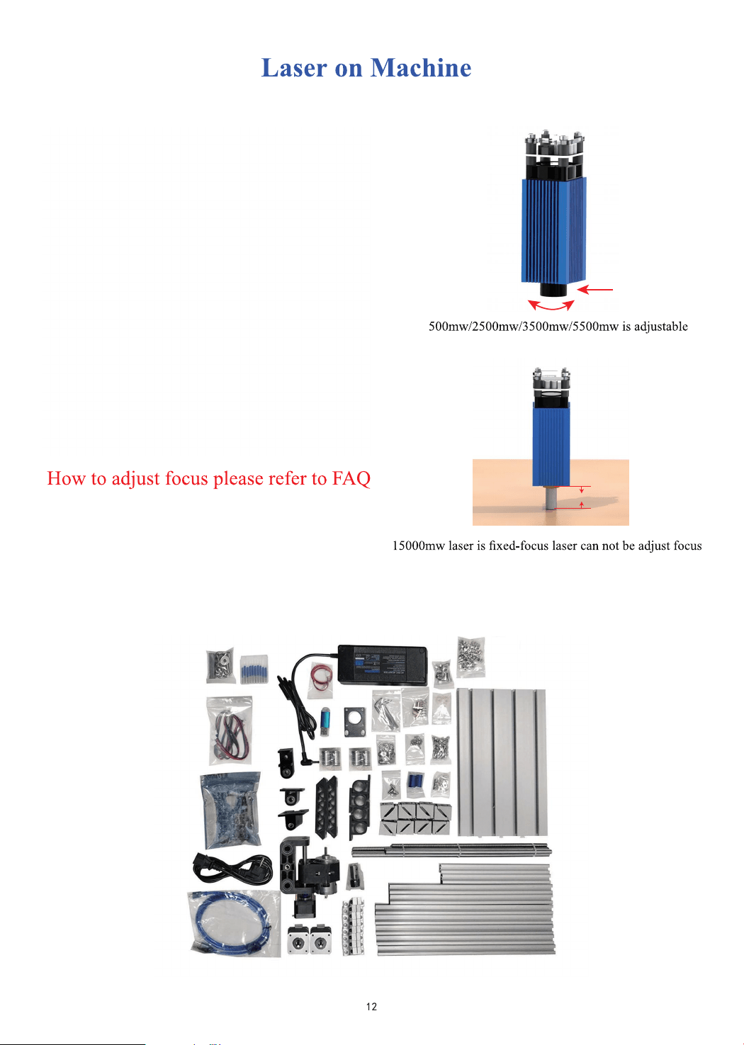
Laser on Machine
Machine Assemble
13
How to connect
12
Package
14
Candle software
19
LaserGRBL
24
Offline instructions
25
FAQ
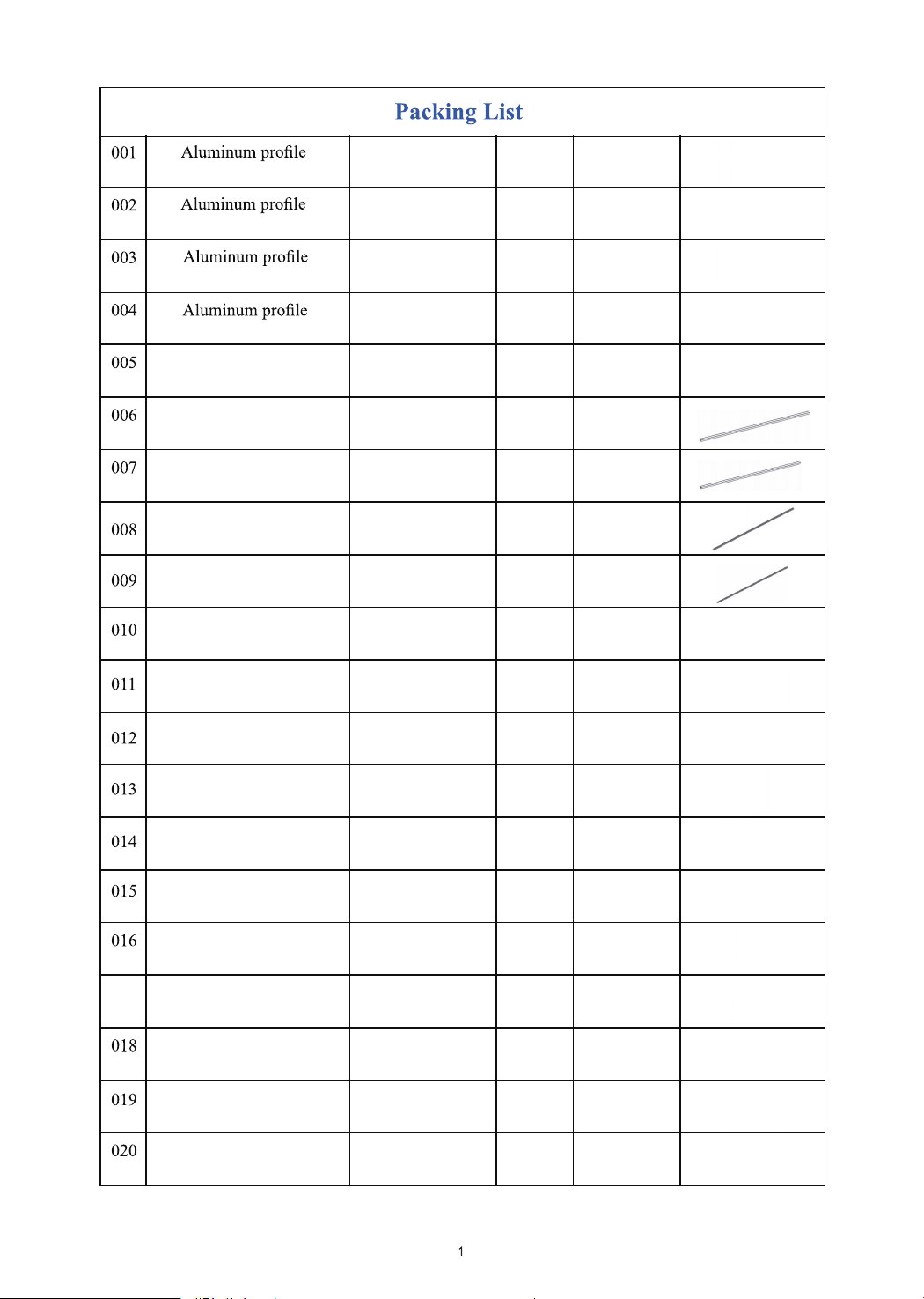
2020*220mm
M3*6
Optical axis
Optical axis
Z-Axis
Lead screw
Lead screw
Stepper Motor
3.0 Controller
USB Cable
775 Motor Cable
Stepper Motor Cable
Hexagon Socket Screw
Hexagon Socket Screw
Hexagon Socket Screw
Hexagon Socket Screw
M5*8
M5*10
T nut
Slide nut
M6*12
15180*250mm
2020*330mm
2020*300mm
Z-axis
Φ10*340mm
Φ10*330mm
T8*340mm
T8*320mm
42HS34-13D
GRBL 1.1
1500mm
500mm
600mm
M6
M5
1
2
5
2
1
2
2
1
1
2
1
1
1
3
8
4
59
10
63
10
Pc
Pc
Pc
Pc
Pc
Pc
Pc
Pc
Pc
Root
Root
Root
Root
Root
Root
Root
Root
Root
Root
Set
017
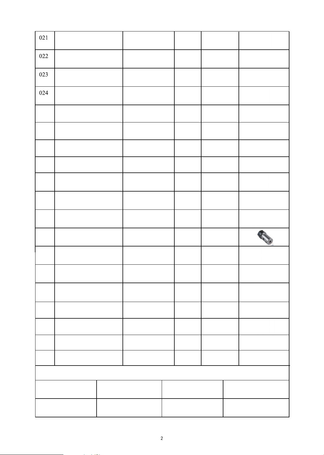
Copper nut
2
Corner piece 2028
Pitch 2 Lead 4
16
Support
Nut seat
SK10
T8
8
1
Linear Bearings
LM10UU 10*19*29
Power supply
ABS isolation column
Drill Bit
Optional
500mw
15000w
1600mw 2500mw
1 Inch Offline 1.8 Inch Offline
3500mw
Motor mounting plate
ER11
X-bearing
Y-bearing
DC24V5A
11*5.2*5
3.175*30°0.1
C16-ER11-35L 5mm
/
/
/
/
/
/
/
1
Word support
2
1
1
1
Pressure plate
Flash Memory Disk
Package
2/2.5/3/4/5 1
Socket wrenches
026 Coupling
027
028
029
030
031
032
033
034
035
036
037
038
039
Gasket
5*8
M5 36
2
1
4
1
1
2
1
4
025
Pair
Pc
Pc
Pc
Pc
Pc
Pc
Pc
Pc
Pc
Pc
Pc
Pc
Pc
Set
Set
Set
Set
Box
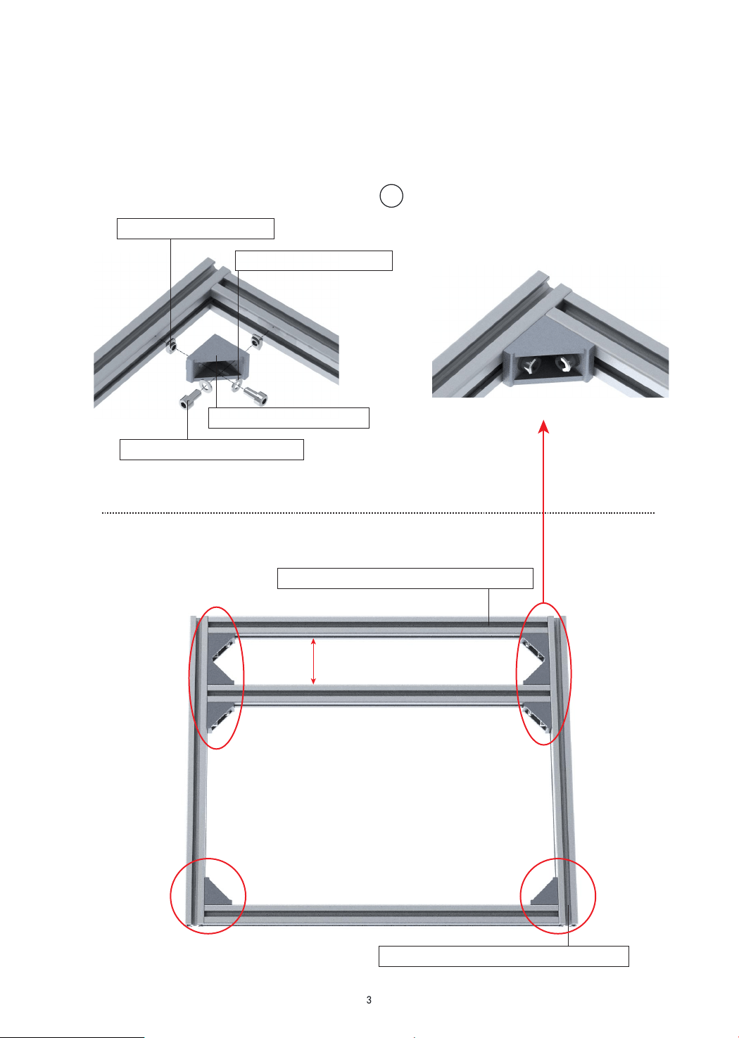
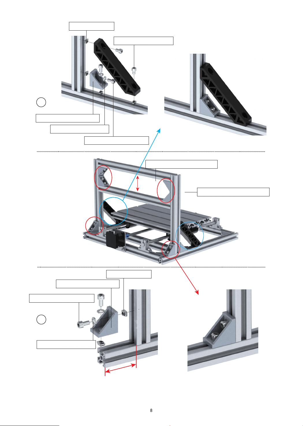
2418 Machine Assemble
022: Corner pieces*1 pc
019:T-nut M5*2 pcs
027:Gasket M5*2 pcs
017: M5-10*2 pcs screw
002: Aluminum Profile330mm*2 root
003: Aluminum Profile300mm*3 root
56mm
1
035: Y-bearing*1 pc
017:M5-10*2 pcs screw
019:T nut*2 pcs
Note: Place the center of the profile
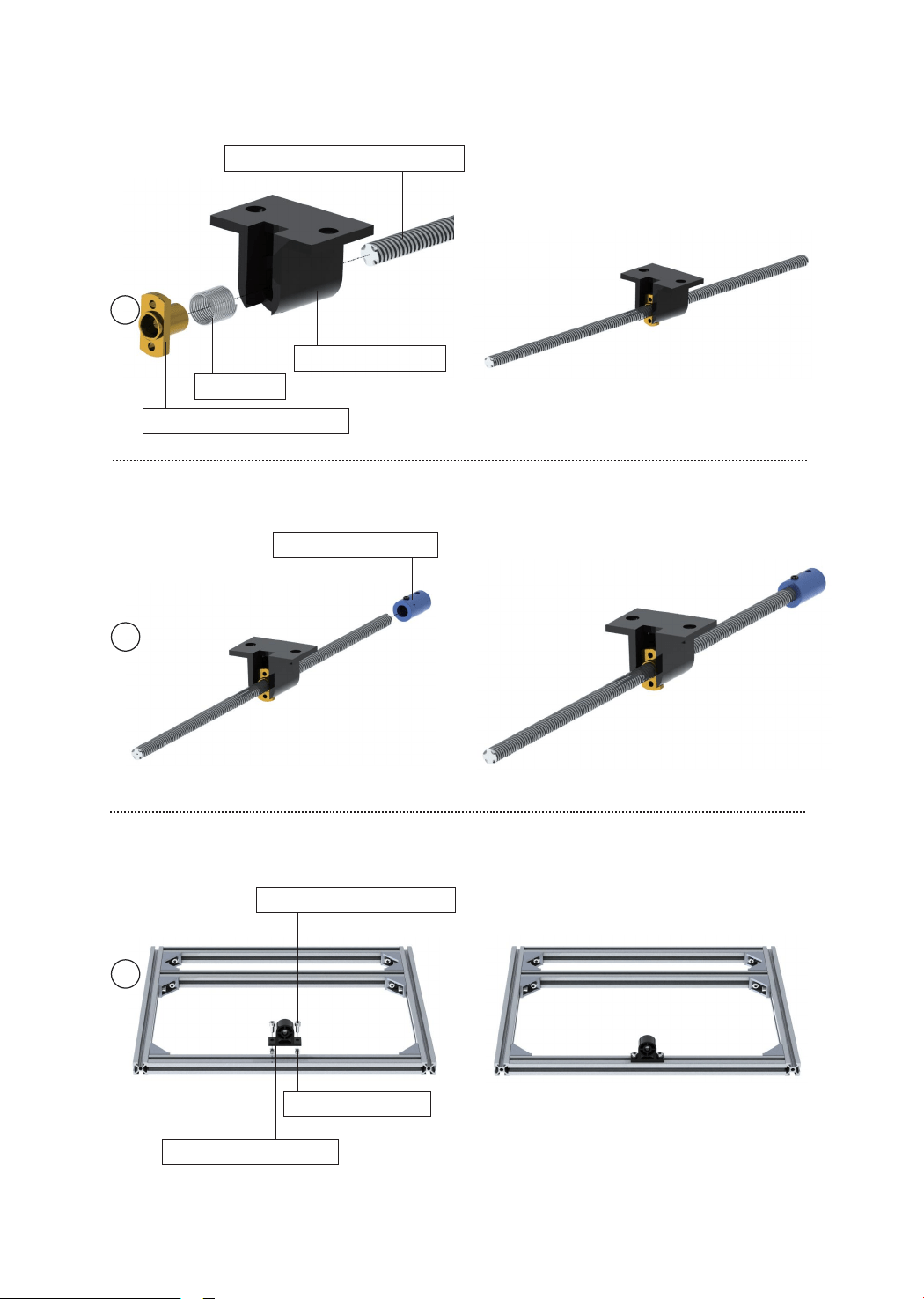
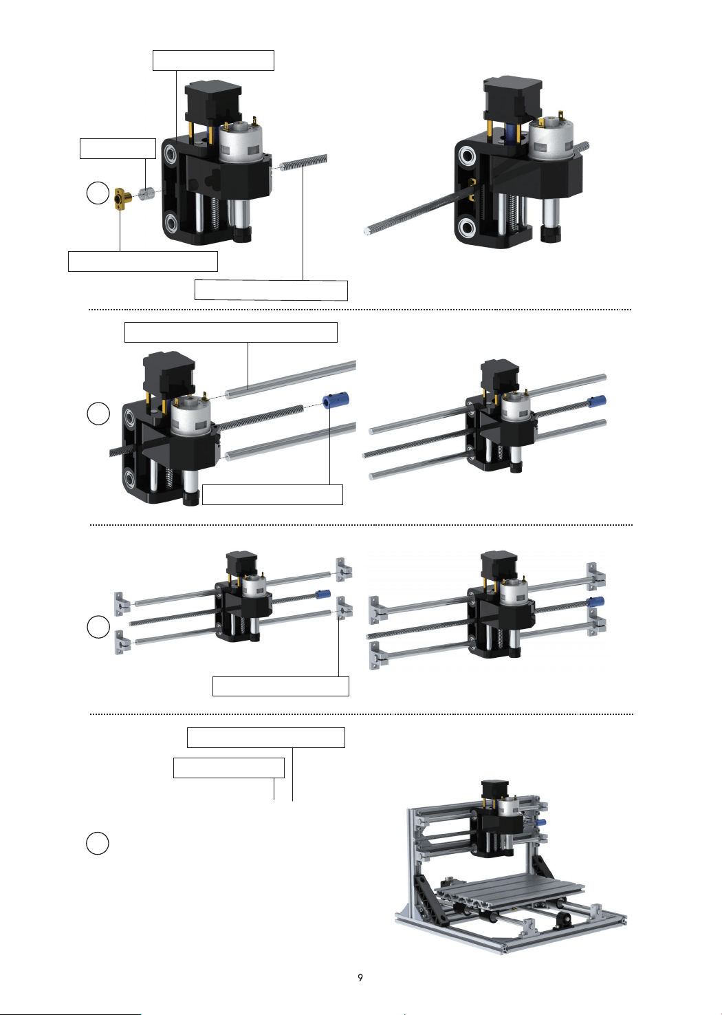
026:Coupling*1 pc
021:Copper nut*1 pair
Spring*1
024:Nut seat*1 pc
009:Lead screw320mm*1 pc
2
3
4
4
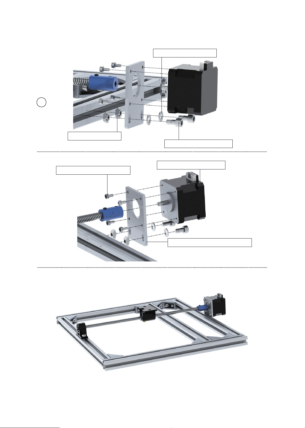
033: Motor mounting plate*1pc
010: Stepper Motor*1 pc
015:M3-6*4pcs Screw
5
019:T nut*2 pc
017: M5-10*2 pcs screw
027:M5 Gasket*2 pcs
5
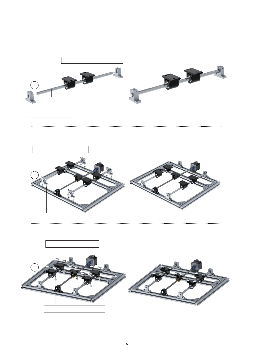
017: M5-10*8 pcs screw
019: T nut*8 pcs
025: Linear Bearings*2 pcs
023: Support*2 pcs
007: Optical axis 330mm*1 root
Y axis assemble belt
018:M6-12*10 pcs screw
020:Slide nut*10 pcs
8
7
6
9
10
11
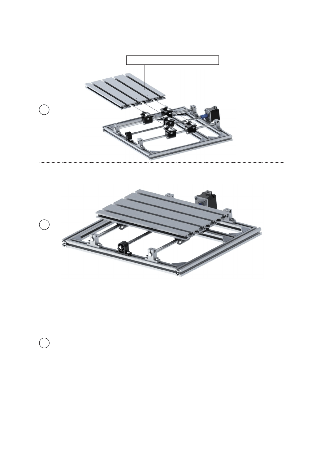
001:Aluminum Profile*1 root
7
017: M5-10*2 pcs screw
017: M5-10*2 pcs screw
027: M5 Gasket*2 pcs
019: T nut*4pcs
027: M5 Gasket*2 pcs
019: T nut*2pcs
022: Corner piece*1pc
022: Corner piece*1pc
016: M5-8*2 pcs screw
003:2020-300mm*2 root
004:2020-220mm*2 root
56mm
12
13
28mm
026:Coupling*1 pc
006:Optical axis 340mm*1 root
017: M5-10*8 pcs screw
019: T nut*8pcs
023:Support*4 pcs
005: Z-Axis*1set
Spring*1
008:T8-340mm*1 pc
021:Copper nut*1 pair
15
16
17
14
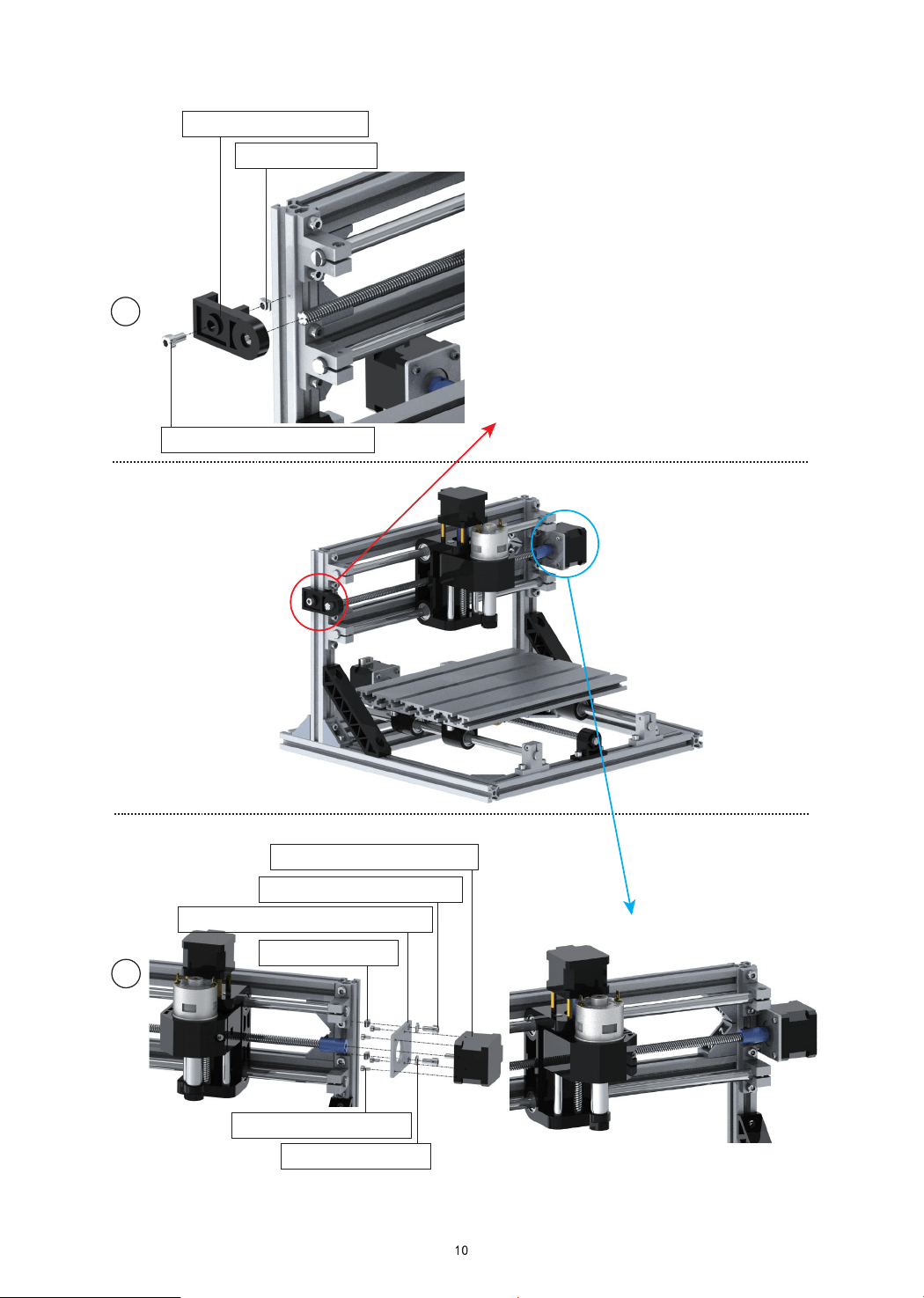
017:M5-10*1 pc screw
019: T nut*1 pc
034: X-bearing*1 pc
18
19
033: Motor mounting plate*1pc
010: Stepper Motor*1 pc
017:M5-10*2 pcs screw
027: Gasket*2 pcs
015:M3-6*4 pcs screw
019: T nut*2 pcs
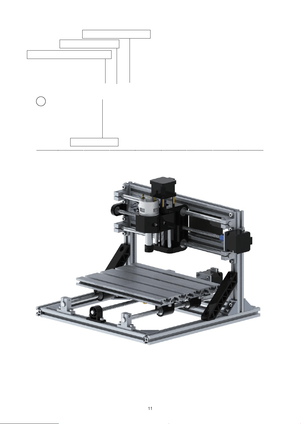
017:M5-10*4 pcs screw
011:Controller*1 pc
019: T nut*4 pcs
030:ABS isolation column*4 pcs
20
2cm
Package
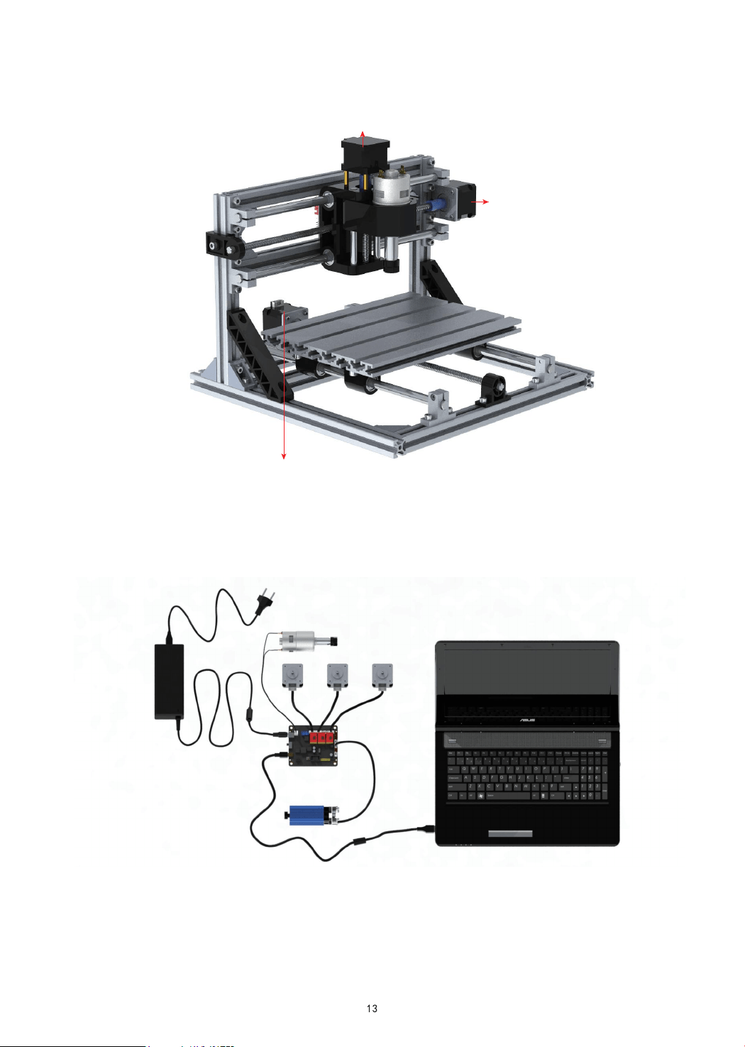
How to connect
Spindle
Power supply
Laser
Computer
X axis motor Y axis motor Z axis motor
X axis motor
Z axis motor
Y axis motor
User manual
1.Overview
Candle is an open source software suitable for CNC machine tool processing. It supports G code file processing and
visual display.
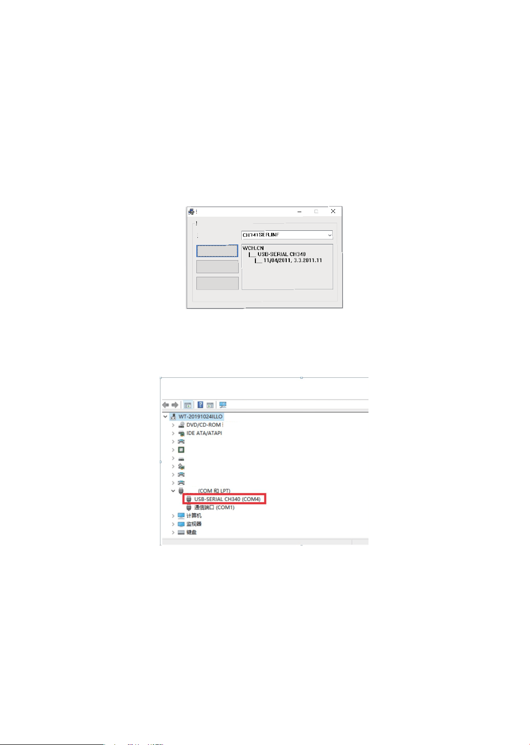
2.Install the driver
For the first time use, please connect the device to the computer via USB cable, and click the CH340-Driver.exe file
in the driver folder to install the driver. Under normal circumstances, the Win10 system will automatically identify
and install the driver. For Win7 and Win8 systems, please install it manually.
Driver install(X64)
Driver install/remove
Choose INF file:
Install
Remove
Help
3. Set the port
After installing the driver, open the device manager of the computer and click on the port option to see the content
inside the red box on the screen shown in the figure below (the port information is in brackets).
Remember the port information queried above, switch to the Candle software interface and click the "Settings" option
in the upper left corner. Selecting the setting will bring up the interface. Under "Connection", select the port name you
queried, select the baud rate 115200, and then click below The icon "Finish" ends the setting
Candle software
14
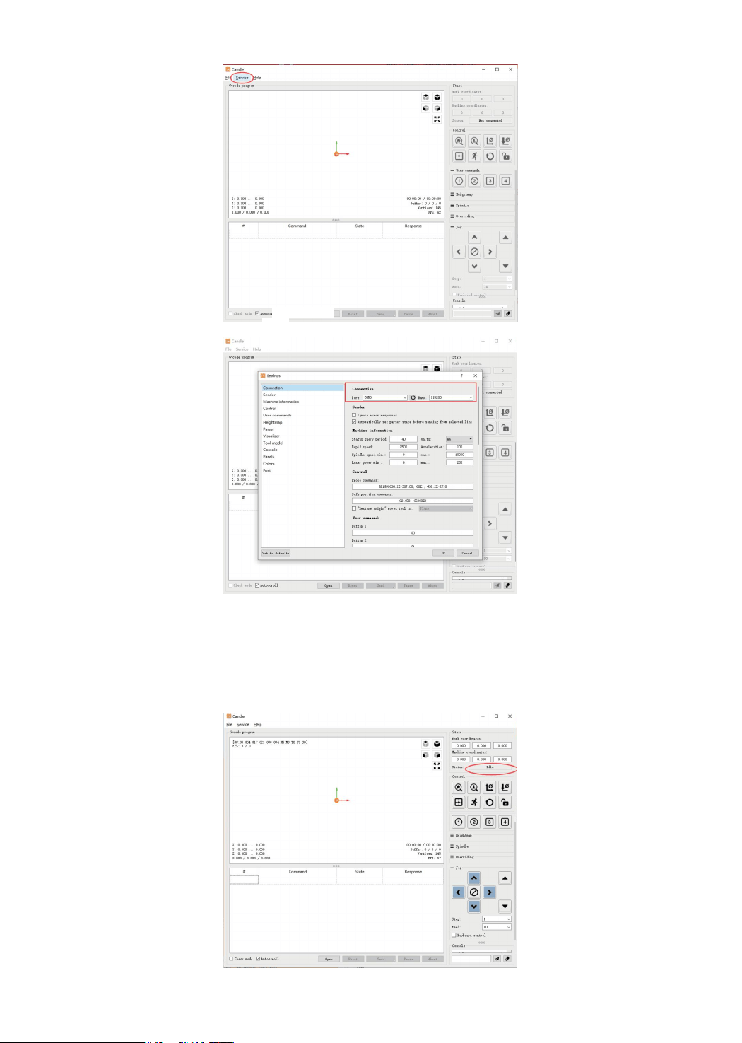
4. Connection is complete
After setting the port and baud rate, click Finish. The status bar at the top right of the Candle interface will show Idle,
and at the same time, the console at the bottom right will display the information shown below, indicating that the
connection has been successfully established.
15
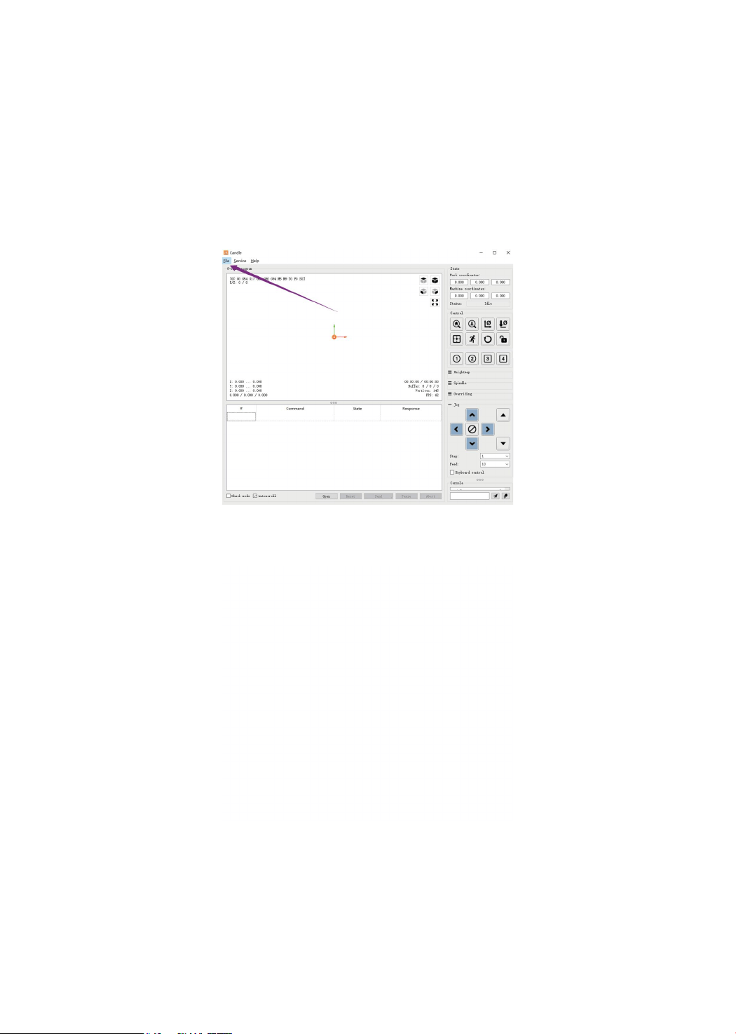
5. Processing documents
The "File" option at the top, click "New" to create a G code in the command bar at the bottom of the interface, and
click "Open" to select a G code file that has been made, and then you can import the file. After importing, the middle
of the interface will display a visual graph composed of tool paths (the position of the pen-shaped graph in the graph
is the current tool position). In the visualization window, hold down the left mouse button to move to rotate the graph,
and hold down the right button to move. Graphics, scrolling the middle wheel can zoom in and out of the graphics.
At the same time, the content of the G code will be displayed in the lower command bar. During processing, the
machine will run one by one according to the G code commands.
16

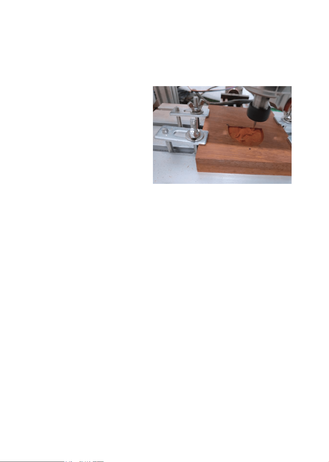
6. Set the working coordinate origin
Before running the G code program, you need to find the position of the engraving figure relative to the overall
engraving plate. There is a three-axis coordinate system in the visual graphics. The origin of the three-axis coordinate
system is the tool setting point of the actual processing graphic. You can move the tool to determine the position of
the engraving graphic relative to the overall engraving plate based on the position of this origin. The engraving figure
in the figure below is taken as an example. After the selected tool position is started, the X, Y, and Z axes are reset to
zero (the axis is reset to zero, and the Z axis is reset to zero buttons). Before returning to zero, make sure
that the tool approaches the distance of one sheet of paper for engraving, and then return the X, Y, and Z axes to zero
(please use a flat-bottom sharp knife when engraving, and use a cylindrical milling cutter when machining planes,
slots, and holes) The effect is that the sculpted figure will be carved with the blade tip as the origin.
17
7.Start Carving
After finding the engraving position, click the send button below and the device will automatically start engraving.
The status bar at the top right shows running. The visualization window shows that the tool is moving along the tool
path. You can choose the pause and stop buttons below when engraving. (After pausing, click again to continue the
previous engraving. After termination, click Send to start processing from the beginning).
8.Finished processing
After the processing is completed, the visualization window prompts that the engraving is completed and the time
required for engraving.
18

LaserGRBL
LaserGRBL is an excellent and practical open source control software in the field of laser engraving. Compared
with similar software, it has a simple interface, simple operation, and supports multiple languages. There are a lot
of learning resources used on the Internet, which is convenient for beginners to understand and master the software.
Mastering a laser engraving software is the basic condition for using a laser engraving machine. It is recommended
that beginners first learn the operation method of the software online before using it to prevent damage to the laser
engraving machine and surrounding items by improper operation
Download from Laser GRBL official website or ask our customer service to get
The archive contains two files:
1.CH340 USB driver Unzip the package and find the file
Double-click to install, the user needs to install this driver when running the software for the first time.
2.Laser GRBL software Locate the file in the archive (install.exe) and double-click it to install it.
Basic operation
1.Install the machine according to the installation instructions, connect the line.
2.Download Laser GRBL software and install.
3.Power on the motherboard with the power adapter.
4.After the power is turned on, it can be operated online through the computer or offline through the touch screen
on the machine (the online operation and offline operation are described in detail later).
5.Place the material to be engraved in the working area of the engraving machine.
6.Turn on the low light, focus by rotating the laser focus knob until a very bright spot appears, then the focus is
complete.
7.Move to the position you want to engrave and click “Positioning”. This point is the machine zero.
8.Select the file to be engraved, select the engraving mode, and then click “Border”. At this time, the weak light is
turned on, and you can walk along the largest frame of the engraved picture or text, so that you can know that the
engraved file is probably engraved in where. If the location is not suitable, you can relocation it until you are sure.
9. Once the positioning is complete, click on "Engraving"
10.During the engraving process, the point "pause", the machine stops moving, the laser turns off; the point "stops",
the laser turns off, the machine returns to zero.
11.After the engraving is completed, the laser is turned off and the machine returns to zero.
Operation notice
Online operation
Online operation is the operation of controlling the device through software after the device is connected to the
computer.
1.Install the software an USB driver
2.Connect the device to the computer with a USB cable
3.Open the Laser GRBL software, select the COM port (except COM1, you can plug and unplug the USB cable to
see which one is) and the baud rate (generally set to 115200), then click the connection, the color of the button will
become darker after the connection is successful (if Click the connect button and the color does not become darker.
You can unplug the USB cable and plug it in again.)
19
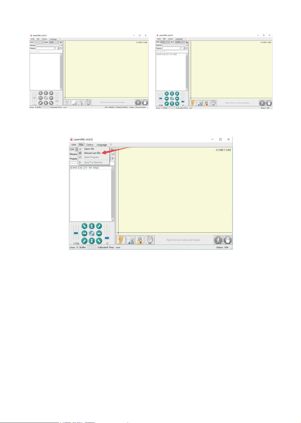
4.After the connection is successful, click “File” on the menu bar of the interface to enter the selection file interface,
select “Open File”, import the picture to be carved, etc.
5.Select the file to be engraved, click “Open”, the “Input Raster Image” dialog box will pop up. Here is the setting
engraving mode and some other engraving parameters. Click “Next” after setting.
20

6.Click “Next” to pop up the “Target Image” dialog box, where you can set the engraving speed, minimum power and
maximum power and the length and width of the image to be engraved and offset. Click “Create” after setting.
Move to the position you want to engrave, click the “Position” button (the position where the laser head is located at
the lower left corner of the engraved pattern), set the number of times to be engraved, and click the “Start Engraving”
button to start the engraving. After the engraving is completed, the machine returns to the zero position.
7.After clicking "Create", enter the preparation for engraving.
21

Engraving material list
Problem summary
The data listed in this list are all reference values. Because each material has different characteristics and differences,
there is a certain error. In general, the use of relatively high power (1600MW is relatively high power compared to
500MW), the engraving depth is relatively deep, but due to the focal length, it will be less detailed than the low
power. Small power engraving is shallow but very fine. When engraving, you can adjust the power, engraving speed,
and moving speed for better results. In addition, when the speed is slow, it can be cut, but if the edge is not fine and
the degree of burning is obvious, you can try to adjust the speed and repeat the engraving several times to achieve
better results. If it is cutting, please adjust the speed as appropriate to achieve the cutting effect. If it is engraving,
please adjust the parameters such as power and speed according to the depth of engraving.
Q : What materials can the laser engraving machine engrave or cut?
Please refer to the "Carving Material List"
Q : What is the difference in power size?
The higher the power, the greater the luminous energy of the laser head, the higher the temperature of the material hit,
the harder the material of the material that can be engraved, and even the full cutting can achieve the cutting effect.
However, the pattern carved out by high power is not small enough for fine power. If it is cutting, it is recommended
to choose high power; if it is required to engrave shallower, more delicate, it is recommended to choose low power.
Q: How long does the laser head last?
In theory it is 8,000 hours. (The life of the laser varies depending on the environment and usage of each user. This
issue is for reference only)
Q: How high can the engraving precision be achieved?
The power is different and the precision of the engraving is different. In general, the larger the power, the larger the
laser spot (the spot on the material), so it cannot be engraved fine. In general, low power (300MW 500MW) engrav-
ing accuracy can be achieved.
Q : Which formats or formats are supported?
Support all formats of images, support GCODE, NC files
Q: Is the laser head focal length adjustable?
Adjustable. Click the “Weak Light On” button on the touch screen interface, then rotate the knob under the laser head
to make the spot on the material as small as possible. The smaller the spot, the greater the energy.
Q : Whether to support the grayscale engraving function
Supports the grayscale engraving function, which can engrave pictures and photos of different shades of color by
controlling the intensity of the laser according to the color depth of the image.
Q : Is there a positioning function? How to locate?
When using online engraving, you can turn on the low light, move the laser head to the place to be engraved, click
the “Position” button to set the point to zero.
When using offline engraving, turn on the low light, move the laser head to the place to be engraved, click the “Posi-
tion” button to set the point to zero, select the file to be engraved, and confirm the range of the photo to be engraved
by walking the border. For accurate positioning.
22

Q: What is the reason why the engraved picture is very light?
Quality: ** line / mm, generally set to 10 lines / mm, the larger the value, the darker the color, the set according to
your needs
Engraving speed: the moving speed when the laser is turned on, the faster the speed is engraved the shallower.
Minimum maximum power: The general minimum power is set to 0 and the maximum power is set to 1000. The
greater the maximum power, the deeper the engraved color.
Q: Why does the fan of the laser module not turn?
Please confirm that the laser head is working properly. If the laser head does not work, there may be a bad contact of
the power supply line of the laser head; if the laser head works normally, the fan may be broken.
Q: What is the reason for the software connection?
Please confirm whether the USB interface is in contact with normal. Please confirm whether the COM port is selected
correctly (do not select COM1); please confirm whether the baud rate is selected correctly (select 115200). If you still
can't solve it, please contact our customer service or technical staff.
Q: What should I do to engrave something taller?
Since the model is a desktop model, the laser head and the object to be carved must reach a certain distance to
engrave. If it is necessary to engrave a higher object, it is necessary to raise the height of the whole machine and the
object to be carved. For example, take the appropriate plane to raise the 4 feet of the machine, but the adjusted
engraving effect cannot be guaranteed. (After adjustment, remember to refocus)
Q : Can the laser head be replaced by itself?
The laser head is self-replaceable. The L-type M3 Allen key can be used to unscrew the locking laser head, remove
the laser head, replace the laser head, and retighten the screws.
Q: Can you emboss wood?
No. Laser engraving can only be planar engraving. Relief needs high and low float
Q: How long does it take to engrave a picture?
The length of time required for engraving depends mainly on the speed of the engraving, the speed of the idling, and
the size of the picture. Users can view the total time spent on the software or on the progress bar on the touch screen.
Q : Do I need to brush the motherboard and touch screen?
The motherboard and touch screen factory are already update firmware, no need to re-flash the firmware. If you need
to change the firmware, you can use the Grbl →Grbl configuration →Value on the software,double-click the option
you want to modify to modify it, and then click "Write" to write it.
Q : Where is the motor drive plugged in?
The small drive is 4988 green board (rated current is 1A, the maximum current is 2A), the X-axis motor drive is
inserted in the X-axis motor in-line drive interface below the X-axis motor line interface; the Y-axis motor drive is
connected to the Y-axis The Y-axis motor is directly inserted into the drive interface below the motor line interface,
and the Y1 and Y2 axes share a Y-axis drive. (Note: the direction of the drive is not reversed, and the insertion will
be burned)
There are two ways to distinguish the direction of the drive: 1. Look at the color of the drive and drive interface termi-
nals.(black and green), the corresponding color can be inserted. 2. Check the words on the back of the motherboard
driver interface (such as EN DIR GND, etc.), and insert the words on the corresponding drive (such as EN DIR GND,
etc.).
23
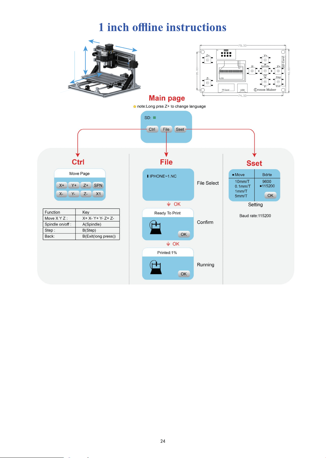
1. Boot page:
X+: right X-: left
Y+: Send $X to the grbl motherboard to unlock the grbl board.
Y-: Send $H to the grbl motherboard to achieve automatic zero return of the grbl board.
OK/SPN: Confirm button.
Move the page: Manually move each axis to the desired position.
X+:
Y+:
OK/SPN: Spindle test switch, press to open the spindle (corresponding to SPN gray on the screen), press again to
close the spindle (the corresponding SPN on the screen returns to normal).
Exit/STP:
Function 1: Tap on each axis button of XYZ to change the movement distance by 0.1, 1, 5, 10 cycles each time.
Function 2: Press and hold for about 2 seconds to exit, and reset grbl, the current position of the machine is set to
absolute 0.
2. File page:
X axis move right direction , X- opposite
Y axis move forward direction, Y- opposite
Z+: Z axis move up direction, Z- opposite
If there is a problem, the corresponding button on the screen turns gray
File list Select the file to be engraved. Support documents include: NC, NCC, TAP, TXT, Gcode, GCO, NL,
CUT,
CNC : Y+: up , Y-: down
OK/SPN: Confirm the selection and enter the confirmation engraving page.
X-
Z+
Y-
Y+
Z-
X+

Q: How to use 500mw -15000mw laser
A: 1. 500mw-3500mw laser , please place the material flat under the laser, and make the distance
between them within 5~10cm ;5500mw laser within 3-5cm (less distance will not be able to
focus). Press the power switch on the laser driver, then the blue light on . Open the software click
weak power, there will be a point on engraved material, just turn around the focus ring on laser
to adjust the smallest which is the best focus.
2.15000mw laser is fixed focus laser which is not adjustable. The fixed focal ength is about 20mm.
Please use the attached focusing column to determine the distance from the engraved object to the
light exit.
Q: Assemble problem
A: Please refer to the assemble video on Youtube.
Q: The software can not be open.
A: 1. Please use Win7 and above system
2. Please refresh the firmware.
Q: The stepper motor can not move.
A: 1. The current not enough, please adjust the screw on controller.
2. Please check the wire order.
3. Please change the A4988 driver module to check whether has problem
Q: Laser module can not burn anything, no light, weak power
A: 1. Please check power,speed setting on software and adjust focus length for laser[refer to
above to adjust focus].
2. Please connect the laser to power supply directly ,if it work normal, it means laser is ok, just
check connection.
Q: The picture engraved is the opposite of the original picture
A: Just need to adjust on software [ Reversal X/Y/Z axis]
Q: The picture engraved distortion.
A: 1. Synchronous belt is loose.
2. Synchronous wheel is loose.
3.After step 2, and confirm laser not work, please contact us to get the solution, if the laser has
Quality issues, we support resend or refund!
4. Settings page:
Settings : X+: right , X-: left , Y+: on , Y-: next
3. Confirm the engraving page:
Confirm that the engraving file is started without errors.
OK/SPN: Confirmation starts, ready to print becomes the progress display percentage, the OK button on the screen
turns gra
y
, and the file selection page is returned after th
e
engraving is completed.
File tool setting: If the file contains G38.2 Z-100, Grbl will perform the tool setting process.
After the spindle
touches the tool block, the screen will limit the tool value returned by the board.
25
0
10
20
30
40
50
2418
CNC Engraving Machine