Loading ...
Loading ...
Loading ...
English 5
When something is obstructing the top
1.
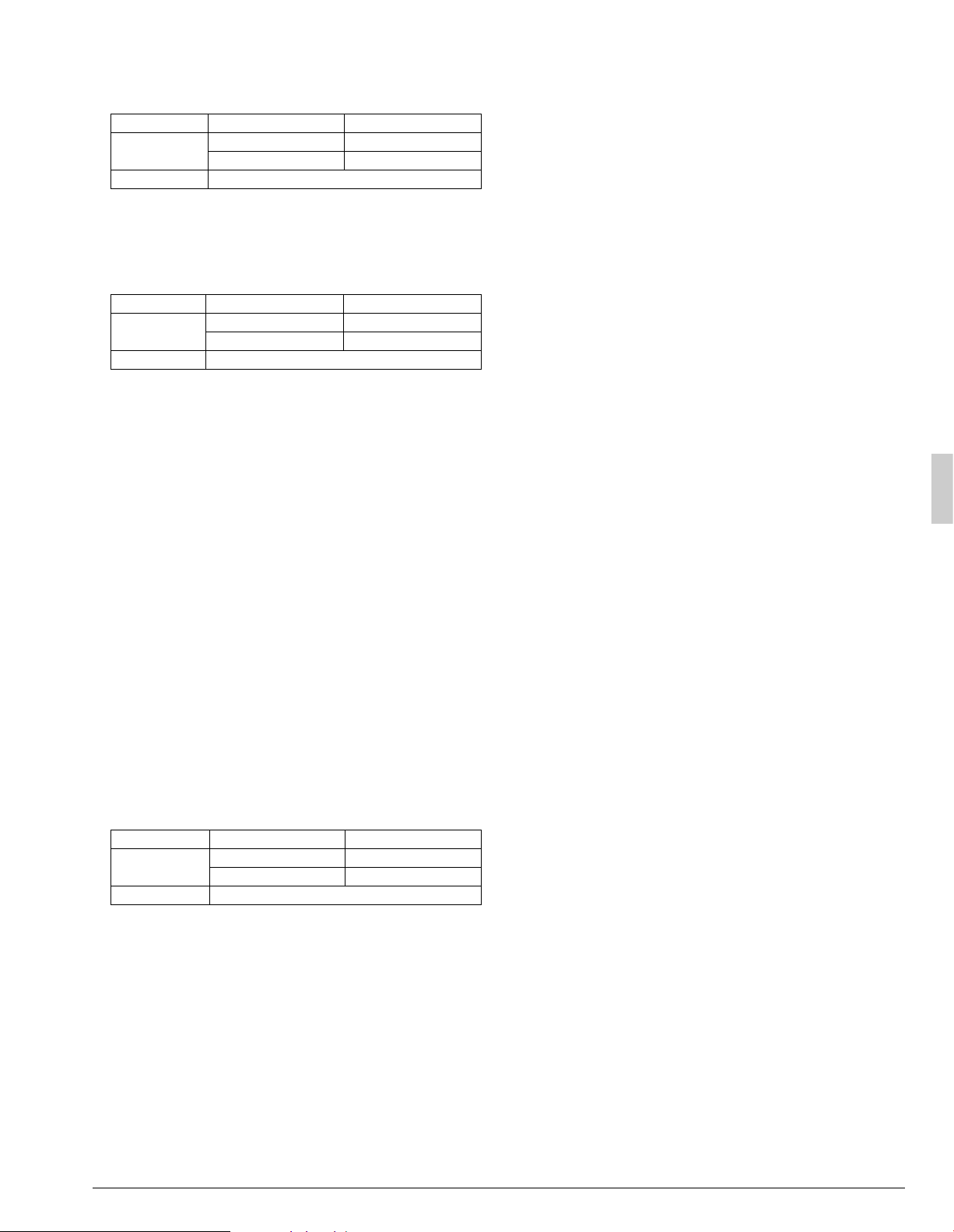
Installation of single unit (Refer to figure 8-[7])
Relation of dimensions of H, A, and L are shown in the table below.
inch (mm)
Note)
Get the lower part of the frame sealed so that air from the outlet does
not bypass.
2.
Series installation (up to two units) (Refer to figure 8-[8])
Relation of dimensions of H, A, and L are shown in the table below.
inch (mm)
Note)
1. Get the lower part of the frame sealed so that air from the outlet
does not bypass.
2. Only two units at most can be installed in series.
(7)-4 IN CASE OF STACKED INSTALLATION
(1) In case obstacles exist in front of the outlet side
(Refer to figure 9-[1])
(2) In case obstacles exist in front of the air inlet (Refer to figure 9-[2])
Note)
1. No more than two units should be stacked.
2. If there is a danger of water from the drain falling on the lower out-
door unit and freezing, install a roof (field supply) as shown in the
figure 9.
3. To prevent the formation and growth of ice in the bottom frame of
the 2nd level outdoor unit, install the outdoor unit so that the bot-
tom frame will be sufficiently higher than the roof. (It is recom-
mended to leave 19.6 in. (500 mm) or more)
4. About 4 in. (100 mm) is required as the dimension for laying the
upper outdoor unit’s drain pipe.
5. Shut off the Z part (the area between the upper outdoor unit and
the lower outdoor unit) so that outlet air does not bypass.
(7)-5 IN CASE OF MULTIPLE-ROW INSTALLATION (FOR ROOF
TOP USE, ETC.)
1.
In case of installing one unit per row (Refer to figure 10-[1])
2.
In case of installing multiple units (2 units or more) in lateral connec-
tion per row (Refer to figure 10-[2])
Relation of dimensions of H, A, and L are shown in the table below.
inch (mm)
5. PRECAUTIONS ON INSTALLATION
• Before installation, make sure the unit is level and the foundation is
sturdy enough to prevent vibration and noise.
• Fasten the unit in place using 4 foundation bolts M12 or equivalent.
It is best to screw in the foundation bolt until their length remains
13/16 in. (20 mm) above the foundation surface.
(Refer to figure 11)
1. Diagram of lower surface
<Drain pipe installation>
• Locations where drain water from the outdoor unit might be a prob-
lem.
In such locations, for example, where the drain water might drip onto
passersby, lay the drain pipe using the separately sold drain plug and
seal up the drain holes in the bottom frame. For details, please con-
tact your dealer.
In case of installing the outdoor unit in cold climates, do not take this
centralized drainage way. Otherwise, drain pipe freeze-up and ice
build-up on the bottom frame way occur.
• When laying the drain pipe, at least 4 in. (100 mm) from the bottom
of the outdoor unit is needed.
• Make sure the drainage works properly.
(Watch out for water leaks if piping is brought out the bottom.)
(Refer to figure 12)
1. Drain plug
2. 4 tabs
3. Drain receiver
4. Insert the drain receiver into the drain plug and hook the
tabs.
5. Bottom frame drain hole
6. (1) Insert the drain plug through the drain hole in the
bottom frame shown in figure 13.
(2) Turn the drain plug along the guides until it stops
(approx. 40°).
7. Guide
(Refer to figure 13)
1. Air outlet side
2. Diagram of lower surface
3. Drain hole (For plug)
4. Drain hole
[How to remove the transport bracket] (30·36·42·48 type)
• A yellow transport bracket and washer are attached to the leg of the
compressor to protect the unit during transportation, so remove
them as shown in figure 14.
(Refer to figure 14)
1. Compressor
2. Securing nut
3. Transport bracket (Yellow)
4. Turn in the direction of the arrow and remove.
(1) Open the sound-proof cover as shown in figure 14.
Do not pull the sound-proof cover or remove it from the compressor.
(2) Remove the securing nut.
(3) Remove the washer.
(4) Remove the transport bracket as shown in figure 14.
(5) Retighten the securing nut.
(6) Return the sound-proof cover as it was.
LA
L
H
0 < L
1/2H 4 (100)
1/2H < L
H8 (200)
H < L Set the frame to be L
H
LA
L
H
0 < L
1/2H 10 (250)
1/2H < L
H12 (300)
H < L Set the frame to be L
H
LA
L
H
0 < L
1/2H 10 (250)
1/2H < L
H 12 (300)
H < L Installation impossible.
Loading ...
Loading ...
Loading ...