Loading ...
Loading ...
Loading ...
English 9
CAUTION
• Use a conduit for field wiring.
• Outside the unit, make sure the low voltage wiring (i.e. for the
remote controller wire, between units, etc.) and the high voltage
wiring do not pass near each other, keeping them at least
2 in. (50 mm) apart.
Proximity may cause electrical interference, malfunctions, and
breakage.
• Be sure to connect the power supply wiring to the power supply wir-
ing terminal block and secure it as described in “7-3 How to con-
nect the power supply wiring”.
• Transmission wiring should be secured as described in “7-4 Trans-
mission wiring connection procedure”.
• Secure wiring with clamp (accessory) to avoid contact with piping.
• Make sure the wiring and the front panel do not stick up above the
structure, and close the panel firmly.
(Refer to figure 22)
1. Fuse/Breaker
2. Power supply
3. Outdoor unit
4. 16V
5. 208/230V
6. Indoor unit
7. Remote controller
8. Ground wire
7-2 How to lay the power supply wiring and trans-
mission wiring
Let the power supply wiring and transmission wiring with a conduit pass
through one of the knockout on the front or side cover, and let the trans-
mission wiring with a conduit pass through another knockout.
• For protection from uninsulated live parts, thread the power supply
wiring and the transmission wiring through the included insulation
tube and secure it with the included clamp.
Precautions knockout
• Open the knockout with a hammer or the like.
•
After knocking out the knockout, we recommend you remove burrs in the knockout and paint
the edges and areas around the edges using the repair paint to prevent rusting.
• When passing wiring through knockout, make sure there are no
burrs, and protect the wiring with protective tape.
(Refer to figure 23)
1. Stop valve fixing plate
2. Power supply wiring (including ground wire) or transmission
wiring.
3. Back of unit
4. Knockout
5. Side of unit
6. Front of unit
7. Terminal block
8. Control Box
<Precautions when laying power supply wiring>
• Wiring of different thicknesses cannot be connected to the power
supply terminal block.
(Slack in the power supply wiring may cause abnormal heat.)
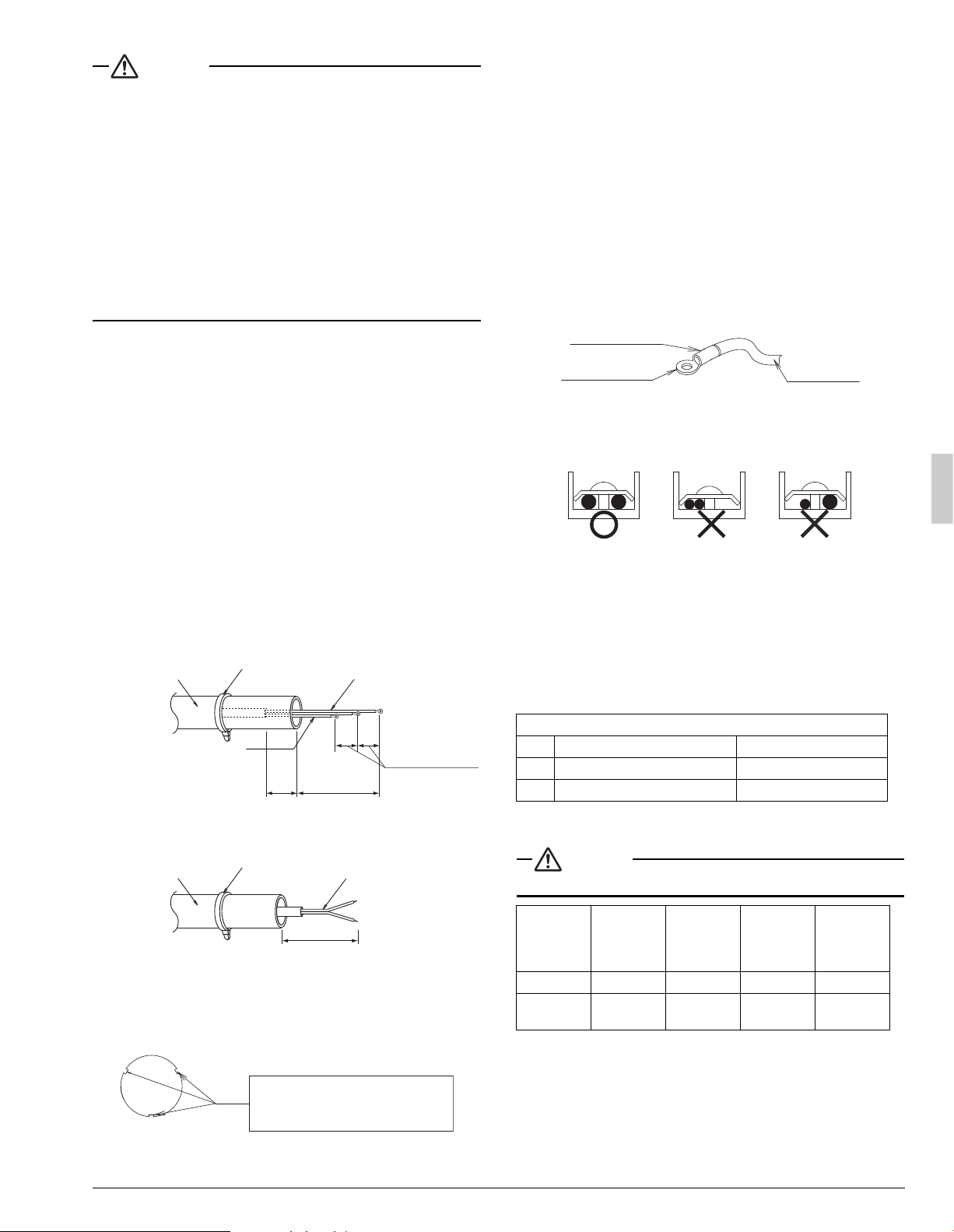
• Use sleeve-insulated round pressure terminals for connections to
the power supply terminal block. When none are available, connect
wire of the same diameter to both sides, as shown in the figure.
Follow the instructions below if the wiring gets very hot due to
slack in the power supply wiring.
• For wiring, use the designated power wire and connect firmly, then
secure using the included clamping material to prevent outside pres-
sure being exerted on the terminal board.
• Use an appropriate screwdriver for tightening the terminal screws.
A screwdriver with a small head will strip the head and make proper
tightening impossible.
• Over-tightening the terminal screw may break it.
See the table below the tightening torque of the terminal screws.
7-3 How to connect the power supply wiring
CAUTION
Attach a circuit breaker or fuse.
Insulation tube
(accessory)
Clamp
(accessory)
Power supply
wiring
3 in. (75 mm)
2 in. (50 mm)
or more
5/8 in. (15.9 mm)
Insulation tube
(accessory)
Clamp
(accessory)
Transmission
wiring
3 in. (75 mm)
<Power supply wiring>
<Transmission wiring>
Ground wire
If small animals might enter the
unit, block the knockout with an
appropriate material (field supply).
Burr
Tightening torque (ft·lbf / N·m)
M5 Power supply terminal 1.76~2.15 / 2.39~2.91
M4 Shield ground 0.87~1.06 / 1.18~1.44
M3 Transmission wiring terminal block 0.58~0.72 / 0.8~0.97
Model
Phase and
frequency
Voltage
Maximum
overcurrent
protective
device
Minimum
circuit
ampacity
18·24 type
1~60Hz 208/230V 25A 16.5A
30·36·
42·48 type
1~60Hz 208/230V 35A 29.1A
Insulating sleeve
Round crimp-style
terminal
Electric Wire
Connect wires
of the same gauge
to both side.
Do not connect
wires of different
gauges.
Do not connect
wires of the same
gauge to one side.
Loading ...
Loading ...
Loading ...