Loading ...
Loading ...
Loading ...
10 English
CAUTION
• The wiring should be selected in compliance with local specifica-
tions. See the table above.
• Always turn off the power before doing wiring work.
• Grounding should be done in compliance with local laws and reg-
ulations.
• As shown in figure 25, when connecting the power supply wiring to
the power supply terminal block, be sure to clamp securely.
• Once wiring work is completed, check to make sure there are no
loose connections among the electrical parts in the control box.
(Refer to figure 24)
1. Stop valve fixing plate
2. Clamp (accessory)
3. Connecting power supply wiring
4. Ground wire (Yellow/Green)
5. Terminal block (X1M)
6. Transmission wiring
7. (To X2M [TO IN/ D UNIT] (F1, F2))
8. Terminal block (X2M)
9. Insulation tube (Large) (accessory)
10. Insulation tube (Small) (accessory)
11. Cut off the insulation tube sticking out of the outdoor unit.
12. Wire clamp and screw (accessory)
7-4 Transmission wiring connection procedure
• If an excessive force is applied while connecting a wire to the termi-
nal block, the connection may be damaged.
(Refer to figure 25)
1. Terminal block (X2M)
2. Use balance type shield wire (with no polarity).
3. Indoor unit
4. Under no circumstances should 208/230V be connected.
Precautions regarding the length of wiring between units
Exceeding the following limits may cause transmission malfunctions, so
observe them.
Max. wiring length Max. 3280 ft. (1000 m)
Precautions regarding wiring between units
• Do not connect 208/230V power supply wiring to terminals for
the transmission wiring. Doing so would destroy the entire sys-
tem.
• Wiring to the indoor unit should be wired to F1 and F2 (TO IN/D unit)
on the outdoor unit’s terminal block (X2M).
NOTE
• The above wiring should be wired using AWG18-16 (0.75-1.25 mm
2
)
stranded, non-shielded wiring.
(See figure 25 for how to ground the shielded parts.)
• All transmission wiring is to be procured on site.
8. ADDITIONAL REFRIGERANT CHARGE
WARNING
• When leaving the unit with the power on, be sure to
switch with another person doing the installation or close
the front panel.
8-1 Before adding refrigerant
• Make sure the following work and inspection is complete, in accor-
dance with the installation manual.
•Piping
• Wiring
• Air tight test, Vacuum drying
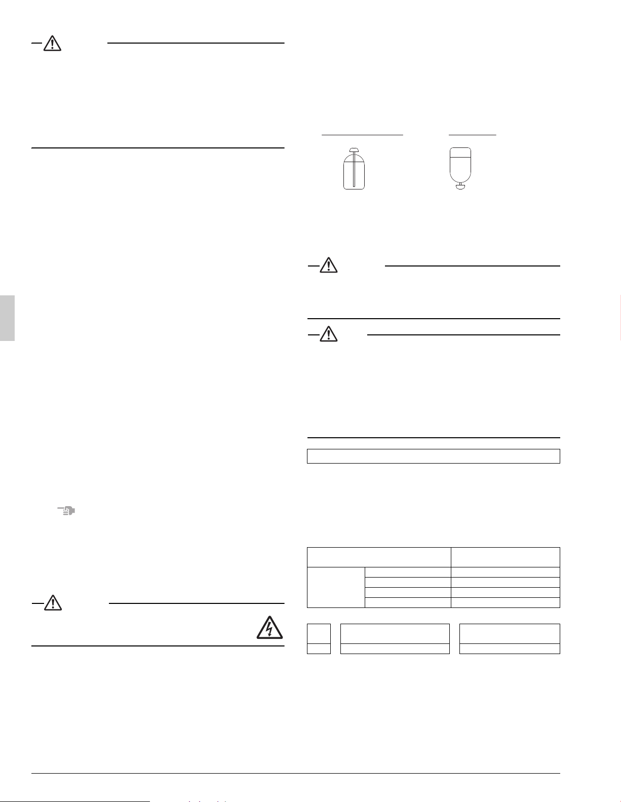
8-2 Checking the refrigerant tank
• Charge the refrigerant to the liquid pipe in its liquid state.
Since R410A is a mixed refrigerant, its composition changes if
charged in a gaseous state and normal system operation would no
longer be assured.
• Check whether the tank has a siphon pipe before charging and place
the tank so that the refrigerant is charged in liquid form. (See the fig-
ure below.)
8-3 Adding refrigerant
WARNING
• To avoid injury always use protective gloves and eye protection
when charging refrigerant.
• To avoid injury do not charge with unsuitable substances.
Use only the appropriate refrigerant.
NOTE
•
Refrigerant cannot be charged until field wiring has been completed.
Refrigerant may only be charged after performing the airtight test
and the vacuum drying (see above).
When charging refrigerant into the system, take care that its maxi-
mum allowable charge is never exceeded, in view of the danger of
liquid hammer.
Refrigerant containers shall be opened slowly.
To avoid compressor breakdown, do not charge the refrigerant
more than the specified amount to raise the condensing pressure.
1.
Calculate the amount of refrigerant to add as described below.
<Calculation for refrigerant charging amount>
Refrigerant equivalent to 15 ft. (4.5 m) liquid piping is factory-charged in
the outdoor unit.
Calculate the refrigerant charging amount based on the following for-
mula.
• If the liquid piping length is 15 ft. (4.5 m) or less (lbs)
• If the liquid piping length is more than 15 ft. (4.5 m)
Record the additional amount to the label stuck on the back of front
panel.
2.
After the vacuum drying is finished, open valve A and charge the cal-
culated amount of refrigerant through the service port for the liquid-
side stop valve.
(See “Stop valve operation procedure” in “6. REFRIGERANT PIP-
ING” for details on how to use the stop valve.)
Filling after calculating the amount of refrigerant to add
Additional refrigerant
charging amount [A]
Indoor unit
type
FAQ, FBQ, FCQ, FHQ
0
FTQ18·24
0.10
FTQ30·36
0.71
FTQ42·48
1.05
[A]
+
(Liquid piping length–15) ft.
× 0.036
=
Additional refrigerant
charging amount
lbs lbs lbs
Tank with siphon pipe Other tanks
There is a siphon
pipe inside, so the
cylinder need not be
upside-down to fill
with liquid.
(Stand the cylinder
upright when filling.)
Stand the tank
upside down and
charge.
Loading ...
Loading ...
Loading ...