Loading ...
Loading ...
Loading ...
6 English
6. REFRIGERANT PIPING
CAUTION
• Do not allow anything other than the designated refrigerant to get
mixed into the refrigerant cycle, such as air, nitrogen, etc. If any
refrigerant gas leaks while working on the unit, ventilate the room
thoroughly right away.
• Use R410A only when adding refrigerant.
6-1 Installation tools
Make sure to use speciality tools to withstand the pressure and to pre-
vent foreign materials from mixing into the system.
6-2 Selecting piping material
CAUTION
Piping and other pressure containing parts shall comply with the
applicable legislation and shall be suitable for refrigerant. Use phos-
phoric acid deoxidized seamless copper for refrigerant.
CAUTION
• All field piping must be installed by a licensed refrigeration techni-
cian and must comply with relevant local and national regulations.
• After piping work is complete, do not under any circumstances
open the stop valve until 7. ELECTRIC WIRING on page 8 and
9. POST-WORK CHECKS on page 11 are complete.
• Do not use flux when brazing the refrigerant piping. Use the phos-
phor copper brazing filler metal (B-Cu93P-710/795:ISO 3677)
which does not require flux. Flux has extremely negative effect on
refrigerant piping systems. For instance, if the chlorine based flux
is used, it will cause pipe corrosion or, in particular, if the flux con-
tains fluorine, it will damage the refrigerant oil.
• Use only pipes which are clean inside and outside and which do not
accumulate harmful sulfur, oxidants, dirt, cutting oils, moisture, or
other contamination. (Foreign materials inside pipes including oils
for fabrication must be 0.14 gr/10 ft. (30 mg/10 m) or less.)
• Use the following items for the refrigerant piping.
Material: Jointless phosphor-deoxidized copper pipe.
Thickness: Select a thickness for the refrigerant piping which com-
plies with national and local laws.
• Maximum piping length and height difference between the outdoor
and indoor units.
6-3 Protection against contamination when install-
ing pipes
• Cover the ends of pipe to prevent moisture, dirt, dust, etc. from enter-
ing the piping.
• Exercise caution when passing copper piping through the through-
holes and when passing them out to the outside.
6-4 Pipe connection
• See “Stop valve operation procedure” in “6-7 Air tight test and vac-
uum drying” regarding handling of the stop valve.
• Only use the flare nuts included with the unit. Using different flare
nuts may cause the refrigerant to leak.
• Be sure to perform a nitrogen blow when brazing.
(Brazing without performing nitrogen replacement or releasing nitro-
gen into the piping will create large quantities of oxidized film on the
inside of the pipes, adversely affecting valves and compressors in the
refrigerating system and preventing normal operation.)
(Refer to figure 15)
1. Refrigerant pipe
2. Location to be brazed
3. Regulator
4. Nitrogen
5. Manual valve
6. Taping
6-5 Connecting the refrigerant piping
• Connection to larger pipe sizes.
In certain configurations this system is designed to be connected to
larger diameter pipe sizes than the standard factory service valves.
If the installation requires use of larger pipe diameters, a field setting
change is required for the system to operate smoothly.
• The local field piping is connectable in four directions.
(Refer to figure 16)
1. Front panel
2. Pipe outlet panel
3. Backward
4. Sideways
5. Downward
6. Pipe outlet panel screw
7. Forward
8. Screw for front panel
• When connecting the pipings downward, remove the knockout
by making four holes in the middle on the each side of the
knockout with a drill.
(Refer to figure 17)
1. Drill
2. Center area around knockout
3. Knockout
4. Slit
Gauge
manifold
Charge hose
•
Make sure to use installation tools that are exclu-
sively made for R410A installations to withstand
the pressure and to prevent foreign materials (e.g.
mineral oils such as SUNISO and moisture) from
mixing into the system.
Vacuum pump
•
Use a 2-stage vacuum pump with a non-return
valve.
•
Make sure the pump oil does not flow backward
into the system while the pump is not working.
•
Use a vacuum pump which can evacuate to
500 microns.
Model 18·24 type 30~48 type
Maximum piping length 164 ft. (50 m) 230 ft. (70 m)
Maximum height
difference
164 ft. (50 m) (outdoor unit above indoor unit)
131 ft. (40 m) (outdoor unit below indoor unit)
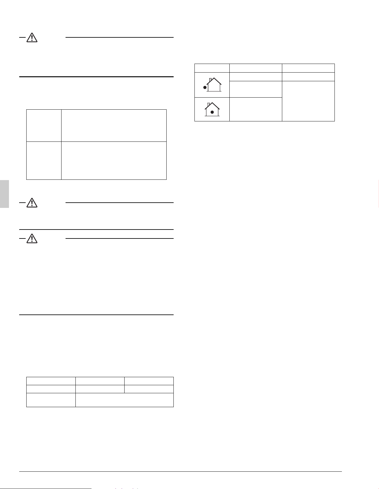
Place Installation Protection method
More than a month Pinch the pipe
Less than a month
Pinch or tape the pipe
Regardless of the period
Loading ...
Loading ...
Loading ...