Loading ...
Loading ...
Loading ...
English 7
• After knocking out the knockout, it is recommended to apply repair
paint to the edge and the surrounding end surfaces to prevent rust-
ing.
(Refer to figure 18)
1. Bottom frame
2. Field piping
<Precautions when connecting pipes>
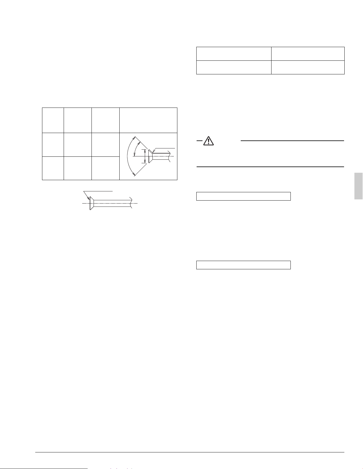
• Please refer to the Table 1 for the dimensions for processing flares.
• When connecting the flare nut, coat the flare both inside and outside
with refrigerating unit oil and initially tighten by hand 3 or 4 turns
before tightening firmly.
• Please refer to the Table 1 for the tightening torque. (Too much tight-
ening will end up in splitting of the flare.)
Ta ble 1
• After all the piping has been connected, use nitrogen to perform a
gas leak check.
Precautions for connecting pipes
• Be careful not to let the field piping come into contact with the com-
pressor terminal cover.
Adjust the height of the insulation material on liquid pipe when it has
the possibility of getting in contact with the terminal. Also make sure
that the field piping does not touch the mounting bolt of the compres-
sor.
(Refer to figure 19)
1. Compressor
2. Corking, etc.
3. Insulation material
4. Bolts
5. Field piping
• If installing the outdoor unit higher than the indoor unit, caulk the
space around insulation and tubes because condensation on the
check valve can seep through to the indoor unit side.
[Preventing foreign objects from entering]
• Plug the pipe through-holes with putty or insulating material (pro
cured locally) to stop up all gaps, as shown in figure 20. (Figure 20
indicates the forward case. Do the same in case of other directions.)
Insects or small animals entering the outdoor unit may cause a short
in the control box.
(Refer to figure 20)
1. Putty or insulating material
2. (field supply)
6-6 Thermal insulation of piping
• Insulate the field piping (liquid and gas-side). (Not insulating them
may cause leaking.)
• The insulation dimension is recommended as following:
•
When using commercial copper pipes and fittings, observe the following:
a)Insulation of pipes should be done after performing air tight test
and vacuum drying.
b)Heat transfer rate: 0.024 to 0.030 BTU/fth°F (0.041 to 0.052 W/Mk
(0.035 to 0.045 kcal/mh°C))
c)Be sure to use insulation that is designed for use with HVAC Sys-
tems.
d)The highest temperature that the gas-side piping can reach is
around 248°F (120°C), so be sure to use insulating material which
is sufficiently resistant to this temperature.
CAUTION
For local insulation, be sure to insulate all the way to the pipe con-
nections inside the unit.
Exposed piping may cause leaks or burns on contact.
6-7 Air tight test and vacuum drying
After doing the piping, perform the following inspections.
Be sure to use nitrogen gas. (See the figure (“Stop valve operation pro-
cedure”) for the location of the service port.)
[Procedure]
Pressurize from the liquid pipes and gas pipes to 550 psi (3.8 MPa)
(and not above 550 psi (3.8 MPa)). If there is not pressure drop over the
next 24 hours, the equipment has passed the test.
If the pressure drops, check for leakage positions. (Confirm that there is
no leakage, then release nitrogen.)
If a FTQ indoor unit is used, only pressurize to 450 psi (3.1 MPa).
Use a vacuum pump that can create a vacuum down to at least
500 microns.
[Procedure]
Operate the vacuum pump for
at least 2 hours
from
both the liquid and
gas pipes
and decrease the pressure to at least
500 microns
.
Leave at below 500 microns for at least 1 hour and make sure that the
vacuum gauge does not rise. (If it does rise, there is either still moisture
in the system or a leak.)
Cases where moisture might enter the piping (i.e., if doing work dur-
ing the rainy season, if the actual work takes long enough that conden-
sation may form on the inside of the pipes, if rain might enter the pipes
during work, etc.)
After performing the vacuum drying for 2 hours, pressurize to 7.2 psi
(0.05 MPa) (i.e., vacuum breakdown) with nitrogen gas, then depressur-
ize down to at least
500 microns
a for an hour using the vacuum pump
(vacuum drying). (If the pressure does not reach at least
500 microns
even after depressurizing for at least 2 hours, repeat the vacuum break-
down - vacuum drying process.) Leave as a vacuum for 1 hour after that,
and make sure the vacuum gauge does not rise.
Pipe size
(in.)
Tightening
torque
A dimen-
sions for
processing
flares (in.)
Flare shape (in.)
3/8”
(9.5 mm)
24.1~29.4
(32.7~39.9 N·m)
0.504~0.520
(12.8~13.2 mm)
5/8”
(15.9 mm)
45.6~55.6
(61.8~75.4 N·m)
0.760~0.776
(19.3~19.7 mm)
A
45
°
± 2
°
90°± 2°
R0.016~0.031
(0.4~0.8 mm)
Refrigerant oil
Ambient temperature: 86°F (30°C),
humidity: Below 80% RH
Ambient temperature: 86°F (30°C),
humidity: 80% RH and above
Minimum thickness: 9/16 inch
(15 mm)
Minimum thickness: 3/4 inch
(20 mm)
Air tight test
Vacuum drying
Loading ...
Loading ...
Loading ...