Loading ...
Loading ...
Loading ...
8 English
(Refer to figure 21)
1. Decompression valve
2. Nitrogen
3. Vacuum pump
4. Valve (Open)
5. Charge hose
6. Stop valve service port
7. Indoor unit
8. Gas line stop valve (Close)
9. Liquid line stop valve (Close)
10. Indicates local procurement
11. Outdoor unit
NOTE
The stop valve must always be turned to “closed”.
Otherwise the refrigerant in the outdoor unit will pour out.
• The names of parts needed to operate the stop valve are shown in
the figure below. The unit is shipped from the factory with the stop
valve turned to the “closed” position.
• Since the side boards may be deformed if only a torque wrench is
used when loosening or tightening flare nuts, always lock the stop
valve with a wrench and then use a torque wrench.
• In cases where the unit is run in heating mode when the outside tem-
perature is low or in other situations where the operating pressure
might drop, seal the gas-side flare nut on the stop valve with silicon
sealant or the like to prevent it from freezing.
Stop valve operation procedure
Have a hex wrench ready (size: 0.2 in. (4 mm) and 0.3 in. (6 mm)).
Opening the valve
1.
Place the hex wrench on the valve stem and turn counter-clockwise.
2.
Stop when the valve stem no longer turns. It is now open.
Close the valve
1.
Place the hex wrench on the valve stem and turn clockwise.
2.
Stop when the valve stem no longer turns. It is now closed.
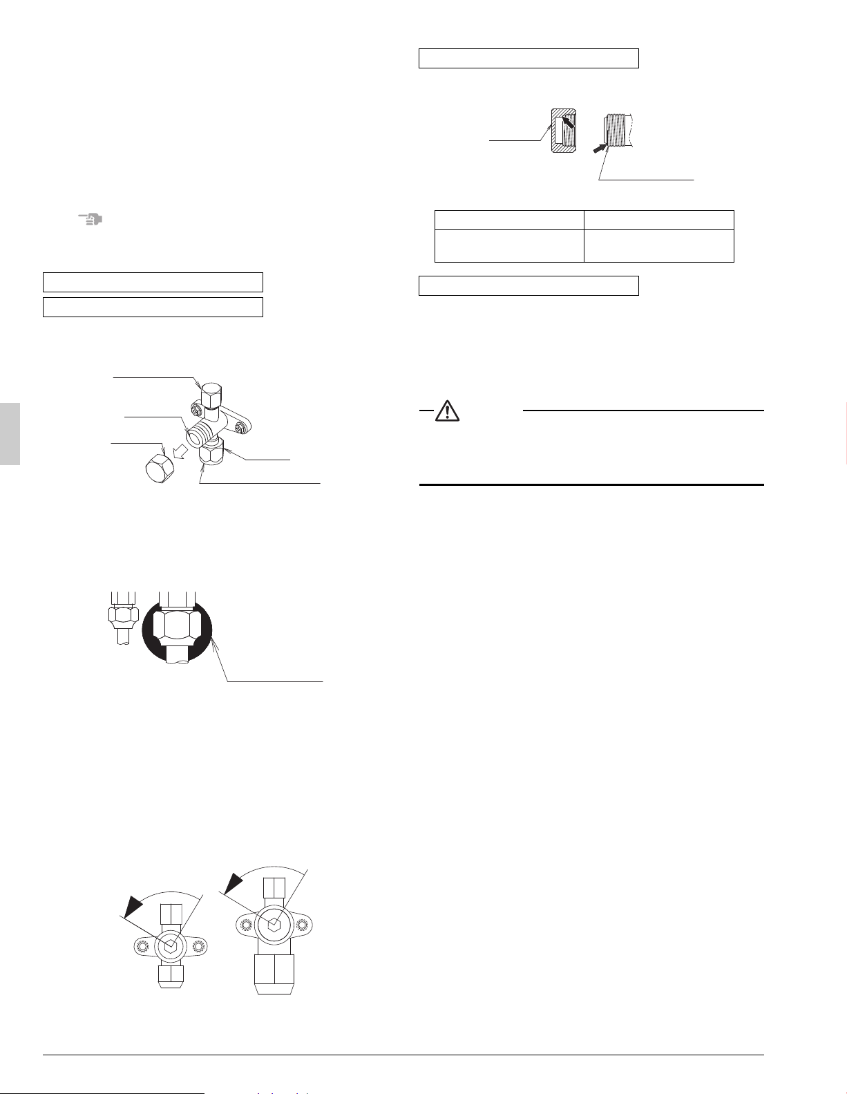
• A seal is attached to the point indicated by the arrow.
Take care not to damage it.
• Be sure to tighten the valve cap securely after operating the valves.
• Use a push-rod-provided charging hose for operation.
• Be sure to tighten the valve cap securely after operation.
Tightening torque ................. 8.5 ~ 10.3 ft·lbf (10.8 ~ 14.7 N·m)
7. ELECTRIC WIRING
CAUTION
To the electrician
• Do not operate until refrigerant piping work is completed.
(Failure to adhere by this caution may lead to irreparable compres-
sor damage.)
7-1 Wiring connection example for whole system
• Electrical wiring work should be done by a certified professional.
• Follow the “Wiring diagram” label when carrying out any electrical
wiring.
Only proceed with wiring work after turning off all power.
• Make sure the ground resistance is no greater than 4.
• Ground the indoor and outdoor units.
• Do not connect the ground wire to gas pipes, sewage pipes, lightning
rods, or telephone ground wires.
• Gas pipes: can explode or catch fire if there is a gas leak.
• Sewage pipes: no grounding effect is possible if hard plastic pip-
ing is used.
• Telephone ground wires and lightning rods: dangerous when
struck by lightning due to abnormal rise in electrical potential in the
grounding.
• Use copper wire.
• When doing the electrical wiring, always shut off the power supply
before working, and do not turn on the switch until all work is com-
plete.
• This unit has an inverter, so it must be grounded in order to reduce
noise and prevent it affecting other appliances, and also to release
any electrical build-up in the unit case due to leaked current.
• Do not install a power-factor improving phase-advancing capacitor
under any circumstances.
(Not only will this not improve the power factor, but it might cause a fire.)
• Connect the wire securely using designated wire and fix it with
attached clamp without applying external pressure on the terminal
parts (terminal for power supply wiring, terminal for transmission wir-
ing and ground terminal). See “7-3 How to connect the power sup-
ply wiring”.
• Leftover wiring should not be wrapped and stuffed into the unit.
• Secure the wiring with the included clamp so that it does not come in
contact with the piping or stop valve.
(See “7-3 How to connect the power supply wiring”.)
Stop valve operation procedure
Precautions when handling the stop valve
Servicing port
Valve stem
Flare nut
Valve cap
Field piping connection
Silicon sealing pad
(Make sure that there is no gap)
Direction to open Direction to open
<Gas pipe><Liquid pipe>
Precautions for handling valve cap
Liquid-side tightening torque Gas-side tightening torque
10.0 ~ 12.2 ft·lbf
(13.5 ~ 16.5 N·m)
16.6 ~ 20.3 ft·lbf
(22.5 ~ 27.5 N·m)
Precautions for handling servicing port
Valve cap
Stop valve
(cap attachment)
Loading ...
Loading ...
Loading ...