Loading ...
Loading ...
Loading ...
4 English
• In areas where the outside air temperature drops below 32°F (0°C)
for more than 12 hours continuously, install a drain-pan heater
(optional accessory) on the bottom frame to prevent the drain from
freezing.
• An optional drain pan heater is available when the unit is installed
in a climate where the drain may freeze.
• The installer should use their local knowledge to determine if this
accessory is necessary to prevent the drain from freezing.
• Do not use a concentrated drain plug (field supply).
(If a drain plug and/or drain pipe are/is used, there is a risk of freez-
ing.)
• If there is a problem with drain dripping from the bottom frame
drain, set up a roof (field supply) below the outdoor unit, or enact
other countermeasures.
• Remove the rear inlet grille to prevent snow from accumulating on
the rear fins.
(4) When there is possibility of short-circuit depending on the ambient
situation, use the wind direction adjusting plate (optional acces-
sory).
(5) The refrigerant gas (R410A) is a safe, non-toxic and non-flammable
gas, but if it leaks into the room, the concentration may exceed tol-
erance levels, especially in small rooms, so steps need to be taken
to prevent refrigerant leakage. See the equipment design reference
for details.
(6) Inverter-type air conditioners sometimes cause static in other elec-
trical appliances.
When selecting an installation location, make sure the air condi-
tioner and all wiring are sufficiently far away from radios, computers,
stereos, and other appliances, as shown in figure 4.
Particularly for locations with weak reception, ensure there is a dis-
tance of at least 9.8 ft. (3 m) for indoor remote controllers, place
power supply wiring and transmission wiring in conduits, and
ground the conduits. Use non-shielded wire for transmission wiring.
(Refer to figure 4)
1. Indoor unit
2. Fuse/Breaker
3. Remote controller
4. Personal computer or radio
(7) Space needed for installation
<Precautions when installing units in series>
• The direction for field piping is either forward or down when install-
ing units in series, as shown in the figure (5~10).
• If the piping is brought out from the back, the outdoor unit will
require at least 10 in. (250 mm) from its right side.
(7)-1 IN CASE OBSTACLES EXIST ONLY IN FRONT OF THE AIR
INLET
When nothing is obstructing the top
1.
Installation of single unit
• In case obstacles exist only in front of the air inlet
(Refer to figure 5-[1])
• In case obstacles exist in front of the air inlet and on both sides of
the unit (Refer to figure 5-[2])
2.
In case of installing multiple units (2 units or more) in lateral connec-
tion per row
• In case obstacles exist in front of the air inlet and on both sides of
the unit (Refer to figure 5-[3])
When something is obstructing the top
1.
Installation of single unit
• In case obstacles exist only in front of the air inlet
(Refer to figure 6-[1])
• In case obstacles exist in front of the air inlet and on both sides of
the unit (Refer to figure 6-[2])
2.
In case of installing multiple units (2 units or more) in lateral connec-
tion per row
• In case obstacles exist in front of the air inlet and on both sides of
the unit (Refer to figure 6-[3])
(7)-2 IN CASE OBSTACLES EXIST IN FRONT OF THE OUTLET
SIDE
When nothing is obstructing the top
1.
Installation of single unit (Refer to figure 7-[1])
2.
In case of installing multiple units (2 units or more) in lateral connec-
tion per row (Refer to figure 7-[2])
When something is obstructing the top
1.
Installation of single unit (Refer to figure 7-[3])
2.
In case of installing multiple units (2 units or more) in lateral connec-
tion per row (Refer to figure 7-[4])
(7)-3 IN CASE OBSTACLES EXIST IN FRONT OF BOTH THE AIR
INLET AND OUTLET SIDES
Pattern 1: Where obstacle in front of the air outlet is higher than the
unit.
(There is no height limit for obstructions on the intake side.)
When nothing is obstructing the top
1.
Installation of single unit (Refer to figure 8-[1])
2.
In case of installing multiple units (2 units or more) in lateral connec-
tion per row (Refer to figure 8-[2])
When something is obstructing the top
1.
Installation of single unit (Refer to figure 8-[3])
Relation of dimensions of H, A, and L are shown in the table below.
inch (mm)
Note)
Close the area under the frame so the outlet air does not bypass
there.
2.
Series installation (up to two units) (Refer to figure 8-[4])
Relation of dimensions of H, A, and L are shown in the table below.
inch (mm)
Note)
1. Close the area under the frame so the outlet air does not bypass
there.
2. No more than two units can be installed in series.
Pattern 2: Where obstacles in front of the air outlet is lower than the
unit.
(There is no height limit for obstructions on the intake side.)
When nothing is obstructing the top
1.
Installation of single unit (Refer to figure 8-[5])
2.
In case of installing multiple units (2 units or more) in lateral connec-
tion per row (Refer to figure 8-[6])
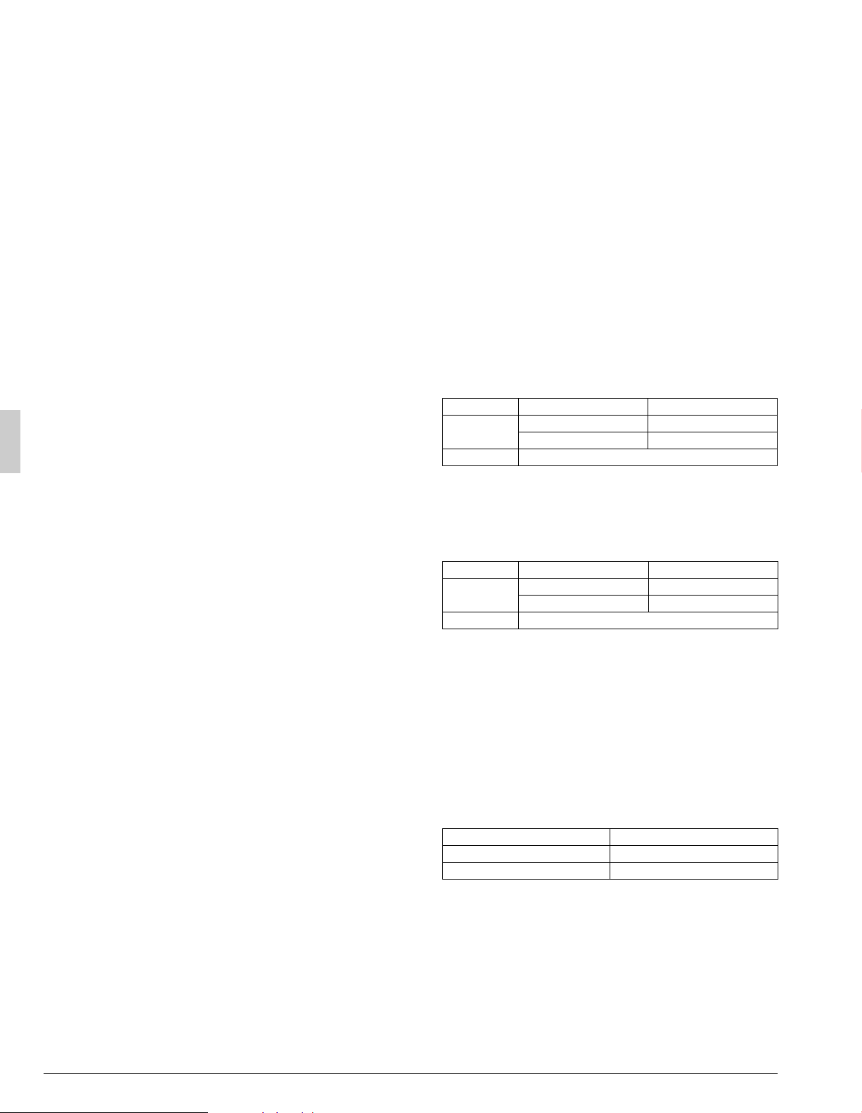
Relation of dimensions of H, A, and L are shown in the table below.
inch (mm)
LA
L
H
0 < L
1/2H 30 (750)
1/2H < L
H 40 (1000)
H < L Set the frame to be L
H
LA
L
H
0 < L
1/2H 40 (1000)
1/2H < L
H 50 (1250)
H < L Set the frame to be L
H
LA
0 < L
1/2H 10 (250)
1/2H < L
H 12 (300)
Loading ...
Loading ...
Loading ...