Loading ...
Loading ...
Loading ...
English 3
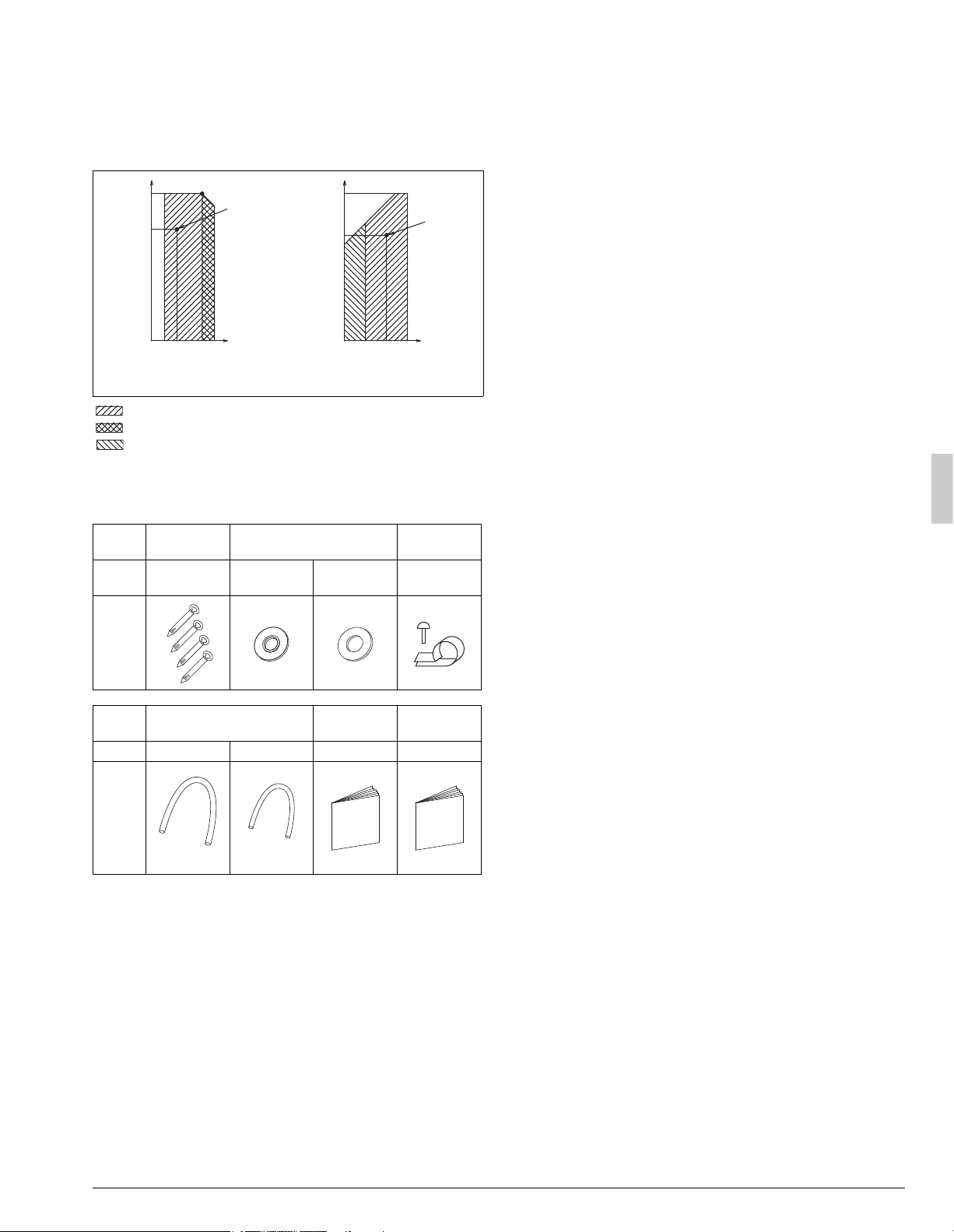
2-1 Standard operation limit
Normal operation
The figures below assume following operating conditions for indoor and
outdoor units:
Equivalent pipe length .................................................. 25 ft. (7.6 m)
Level difference.................................................................. 0 ft. (0 m)
Cooling Heating
Range for operation
Range for pull down operation
Range for warming up operation
2-2 Standard supplied accessories
Make sure that the accessories shown below are all present.
(The accessories can be found behind the front panel.)
(Refer to figure 1)
1. Accessories
2. Screw for front panel
3. Front panel
3. BEFORE INSTALLATION
<Transporting the unit>
As shown in figure 2, move the unit slowly. (Take care not to let hands or
other objects come in contact with rear fins.)
(Refer to figure 2)
1. Air outlet grille
2. Intake hole
3. Corner
4. Outdoor unit
5. Handle
6. Front
7. Rear
8. Always hold the unit by the corners, as holding it by the side
intake holes on the casing may cause them to deform.
Use only accessories and parts which are of the designated specifica-
tion when installing.
4. SELECTING INSTALLATION SITE
(1) Select an installation site where the following conditions are
satisfied and that meets with your customer’s approval.
• Places which are well-ventilated.
• Places where the unit does not bother next-door neighbors.
• A location where small animals will not make nests in the unit.
• Safe places which can withstand the unit’s weight and vibration and
where the unit can be installed level.
• A locations where there is enough space to install the unit.
• Places where the indoor and outdoor unit’s piping and wiring
lengths come within the allowable ranges.
• A location where there is no risk of flammable gas leaking.
(2) If the unit is installed in a location where it might be exposed to
strong wind, install as per figure 3.
• 11 mph (5 m/s) or higher winds blown against the outdoor unit’s
exhaust cause a deterioration in the system performance. High
winds force re-circulation of the exhaust air into the inlet, which is
known to cause the following effects:
• Reduction in performance.
• Increased frost formation in heating mode.
• System shut down due to increased pressures.
• If very strong wind blows continuously on the air outlet side of the
outdoor unit, the fan may turn in reverse at high speed and break,
so install as per figure 3.
(Refer to figure 3)
1. Turn the air outlet side toward the building’s wall, fence or
windbreak screen.
2. Air inlet grille
3. Ensure there is enough space for installing the unit.
4. Set the outlet side at a right angle to the direction of the
wind.
5. Strong wind
6. Blown air
(3) When installing the unit in a place frequently exposed to snow,
pay special attention to the following:
• Install the outdoor unit on a stand (field supply), so that the bottom
frame is more than 20 in. (500 mm) higher than the expected snow
fall to prevent it from being covered by snow.
• Attach a snow hood (field supply) and a snow vizor (field supply).
• Avoid installation at the place where a snowdrift is generated.
• Further, perform the following countermeasures, since there is risk
that the drain water produced at the defrost operation freezes.
• Install the outdoor unit so that its bottom place level has a sufficient
height from foundation level, so that ice does not grow at the lower
surface of the bottom place of the outdoor unit. (Recommended
clearance: 20 in. (500 mm) or more)
Name Clamp Conduit mounting plate
Wire clamp
and screw
Quantity 4 pcs. 2 pcs. 2 pcs.
1 (only 18·24
type)
Shape
Name Insulation tube
Installation
manual
Warranty
card
Quantity 1 pc. 1 pc. 1 1
Shape
67
(19)
57.2
(14)
77
(25)
50
(10)
23(–5)
82.4
(28)
Outdoor temperature °FDB (°CDB)
95(35)
122(50)
Indoor temperature
°FWB (°CWB)
Rated
cooling
capacity
41(5)
–4(–20)
50
(10)
68
(20)
43(6)
80.6
(27)
59
(15)
Outdoor temperature °FWB (°CWB)
60(15.5)
Rated
heating
capacity
Indoor temperature
°FDB (°CDB)
(Large)
(Small)
Loading ...
Loading ...
Loading ...