Loading ...
Loading ...
Loading ...
12 English
10-2 Temperature control operation checklist
• After check operation is complete, check the temperature control
using normal operation.
(Heating is not possible if the outdoor temperature is 75°F (24°C) or
higher.)
(1) Make sure the indoor and outdoor units are operating normally.
(If liquid compression by the compressor or other abnormal
noises can be heard, stop the unit immediately, heat the crank
case for a sufficient amount of time, and try again.)
(2) Check to see if cold (or hot) air is coming out of the indoor unit.
(3) Press the fan direction and fan speed buttons on the indoor unit
to see if they operate properly.
<Precautions during temperature control checks>
• For around 5 minutes after the compressor stops, the compressor
will not run even if the “On/Off” button on the remote controller is
pressed.
• When the system operation is stopped by the remote controller, the
outdoor unit may continue operating for up to 1 minute.
• Malfunction code “U3” is displayed if check operation is not per-
formed using the test operation button the first time after installation.
Perform the check operation in accordance with “10-1 Power On–
Check Operation”.
[Remote controller displays malfunction code]
(Check on a remote controller)
• When using a central controller, see the installation manual or ser-
vice manual which came with the central controller.
[If nothing is displayed on the remote controller]
• There might be a problem with the connections or communication
between the indoor unit and the remote controller.
Make sure all the wiring is properly connected.
CAUTION
To the piping installer, To the electrician
After the test operation, when handing the unit over to the customer,
make sure the front panel on the unit and all screws are attached.
10-3 Final refrigerant charge adjustment
It is not necessary to do this final adjustment normally, but perform the
following operation only when the most adequate refrigerant charge for
the best performance is required and the piping length between the out-
door and indoor units is less than 50 ft. (15 m).
The outdoor temperature must be between 65°F (18°C) and 105°F (40°C).
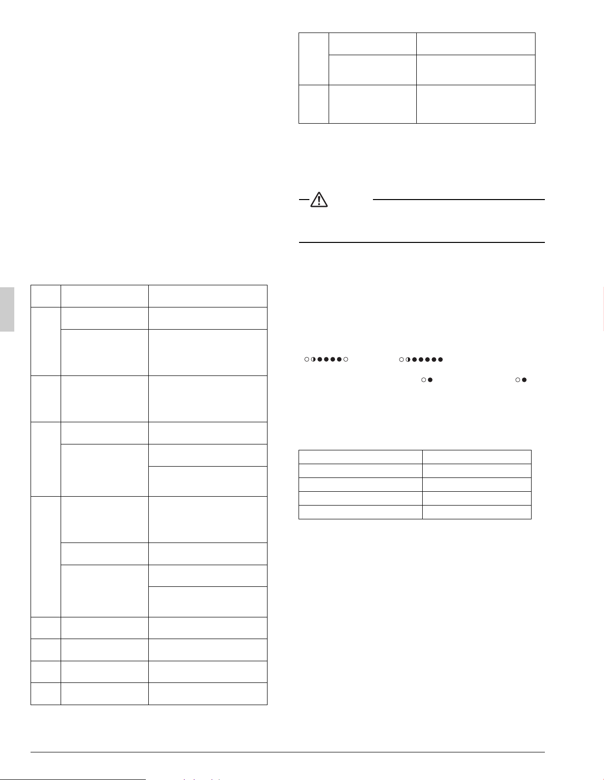
The number of revolutions of the compressor must be greater than or
equal to the charge mode. (It can be confirmed by LED display on PC
board)
The number of revolutions of the compressor LED display.
( :Chargeable :Impossible to charge)
Run the system for 60 minutes in cooling by the forced operation using
the field setting mode 2, No.20 LED :ON, mode 2, No.7 LED :ON,
(Refer to Service Manual.) to allow pressures to stabilize.
Check subcooling of outdoor unit at LSV. Systems should have the tar-
get subcooling in the table below.
a.
If the subcooling is low, add charge little by little to raise subcooling
to the target value. (The maximum additional charge is 2.2 lbs. (1kg))
b. If the subcooling is high, remove charge to lower the subcooling to
the target value.
11. ENERGY SAVING AND OPTIMUM
OPERATION
The unit is equipped with advanced energy saving functionality.
Depending on the priority, emphasis can be put on energy saving or
comfort level. Several parameters can be selected, resulting
in the optimal balance between energy consumption and comfort for the
particular application.
Several patterns are available and explained below. Modify the param-
eters to the needs of your building and to realize the best balance
between energy consumption and comfort.
Refer to Service Manual for changing the field settings.
Setting definition: [A-B]=C; A=mode, B=setting NO., C=setting value.
Malfunc-
tion code
Installation error Remedial action
E3
The stop valve of outdoor unit
is left closed.
Open the gas-side stop valve and the liq-
uid-side stop valve.
Refrigerant overcharge.
Recalculate the required amount of refrig-
erant from the piping length and correct
the refrigerant charge level by recovering
any excessive refrigerant with a refriger-
ant recovery unit.
F6 Refrigerant overcharge.
Recalculate the required amount of refrig-
erant from the piping length and correct
the refrigerant charge level by recovering
any excessive refrigerant with a refriger-
ant recovery unit.
E4
The stop valve of outdoor unit
is left closed.
Open the gas-side stop valve and the liq-
uid-side stop valve.
Insufficient refrigerant.
Check if the additional refrigerant charge
has been finished correctly.
Recalculate the required amount of refrig-
erant from the piping length and add an
adequate amount of refrigerant.
F3
Refrigerant overcharge.
Recalculate the required amount of refrig-
erant from the piping length and correct
the refrigerant charge level by recovering
any excessive refrigerant with a refriger-
ant recovery unit.
The stop valve of outdoor unit
is left closed.
Open the gas-side stop valve and the liq-
uid-side stop valve.
Insufficient refrigerant.
Check if the additional refrigerant charge
has been finished correctly.
Recalculate the required amount of refrig-
erant from the piping length and add an
adequate amount of refrigerant.
U2
Insufficient power supply volt-
age
Check to see if the power supply voltage
is supplied properly.
U3
If check operation has not been
performed.
Perform check operation.
U4
No power is supplied to out-
door unit.
Turn the power on for the outdoor
unit.
UA
If no dedicated indoor unit is
being used.
Check the indoor unit. If it is not a dedi-
cated unit, replace the indoor unit.
UF
The stop valve of outdoor unit is
left closed.
Open the gas-side stop valve and the liq-
uid-side stop valve.
If the right indoor unit piping and
wiring are not properly con-
nected to the outdoor unit.
Make sure that the right indoor unit piping
and wiring are properly connected to the
outdoor unit.
UH
If the transmission wiring has
not be connected or it has
shorted.
Make sure the transmission wiring is cor-
rectly attached to terminals (X2M) F1/F2
(TO IN/D UNIT) on the outdoor unit circuit
board.
Model Target subcooling
18·24 type 6±1°F (3.33±0.56°C)
30·36 type 7±1°F (3.89±0.56°C)
42 type 8±1°F (4.44±0.56°C)
48 type 9±1°F (5.00±0.56°C)
Loading ...
Loading ...
Loading ...