Loading ...
Loading ...
Loading ...
push push
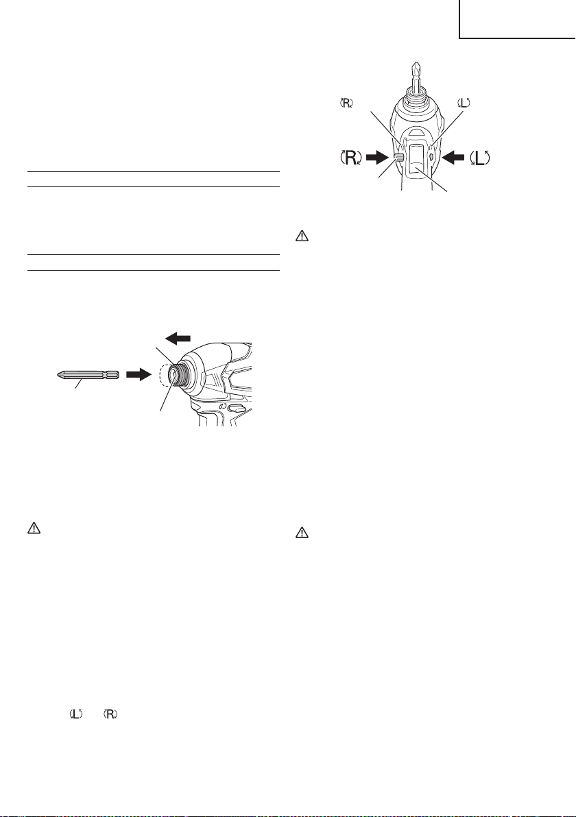
marks
marks
Trigger switch
Pushing button
Fig. 10
CAUTION
The pushing button can not be switched while
the power tool is turning. To switch the pushing
button, stop the power tool, then set the pushing
button.
5 Switch operation
○
When the trigger switch is depressed, the tool rotates.
When the trigger is released, the tool stops.
○
The rotational speed can be controlled by varying
the amount that the trigger switch is pulled. Speed
is low when the trigger switch is pulled slightly and
increases as the trigger switch is pulled more.
○
When releasing the trigger of the switch, the brake will
be applied for immediate stopping.
NOTE
A buzzing noise is produced when the motor is about
to rotate; this is only a noise, not a machine failure.
6. Using the hook
The hook is used to hang up the power tool to your
waist belt while working.
CAUTION
●
When using the hook, hang up the power tool
fi rmly not to drop accidentally.
If the power tool is dropped, it may lead to an
accident.
●
When electing to carry the tool hooked to your
hip belt, make sure to detach the tool bit and side
handle.
Failure to do so may result in unexpected injury.
●
Install securely the hook. Unless the hook is
securely installed, it may cause an injury while
using.
(4) When charging is completed
○
The USB power indicator lamp will not go out when a
USB device has been completely charged.
To verify charge status, check the USB device.
○
Turn the USB power switch OFF and unplug the power
cord from the electrical outlet. (Fig. 8)
○
Remove the battery from the charger and place the
rubber cover over the USB port.
BEFORE USE
Check the work area to make sure that it is clear of debris
and clutter.
Clear the area of unnecessary personnel. Ensure that
lighting and ventilation is adequate.
OPERATION
1. Installing the bit
Always follow the following procedure to install driver
bit. (Fig.9)
Driver bit
Hexagonal hole in the anvil
Guide sleeve
Movement
Fig. 9
(1) Pull the guide sleeve forward.
(2) Insert the bit into the hexagonal hole in the anvil.
(3) Release the guide sleeve and it returns to its origianl
position.
CAUTION
If the guide sleeve does not return to its original
position, then the bit is not installed properly.
2. Removing the bit
Please do the opposite point on the method of
installing bit.
3. Confi rm that the battery is mounted correctly.
4. Check the rotational direction.
The bit rotates clockwise (viewed from the rear side)
by pushing the R-side of the pushing button.
The L-side of the pushing button is pushed to
turn the bit counterclockwise (See Fig. 10).
(The
and marks are provided on the body.)
15
English
000WH18DBDL2metabo.indb15000WH18DBDL2metabo.indb152020/11/0610:24:352020/11/0610:24:35
Loading ...
Loading ...
Loading ...