Loading ...
Loading ...
Loading ...
9
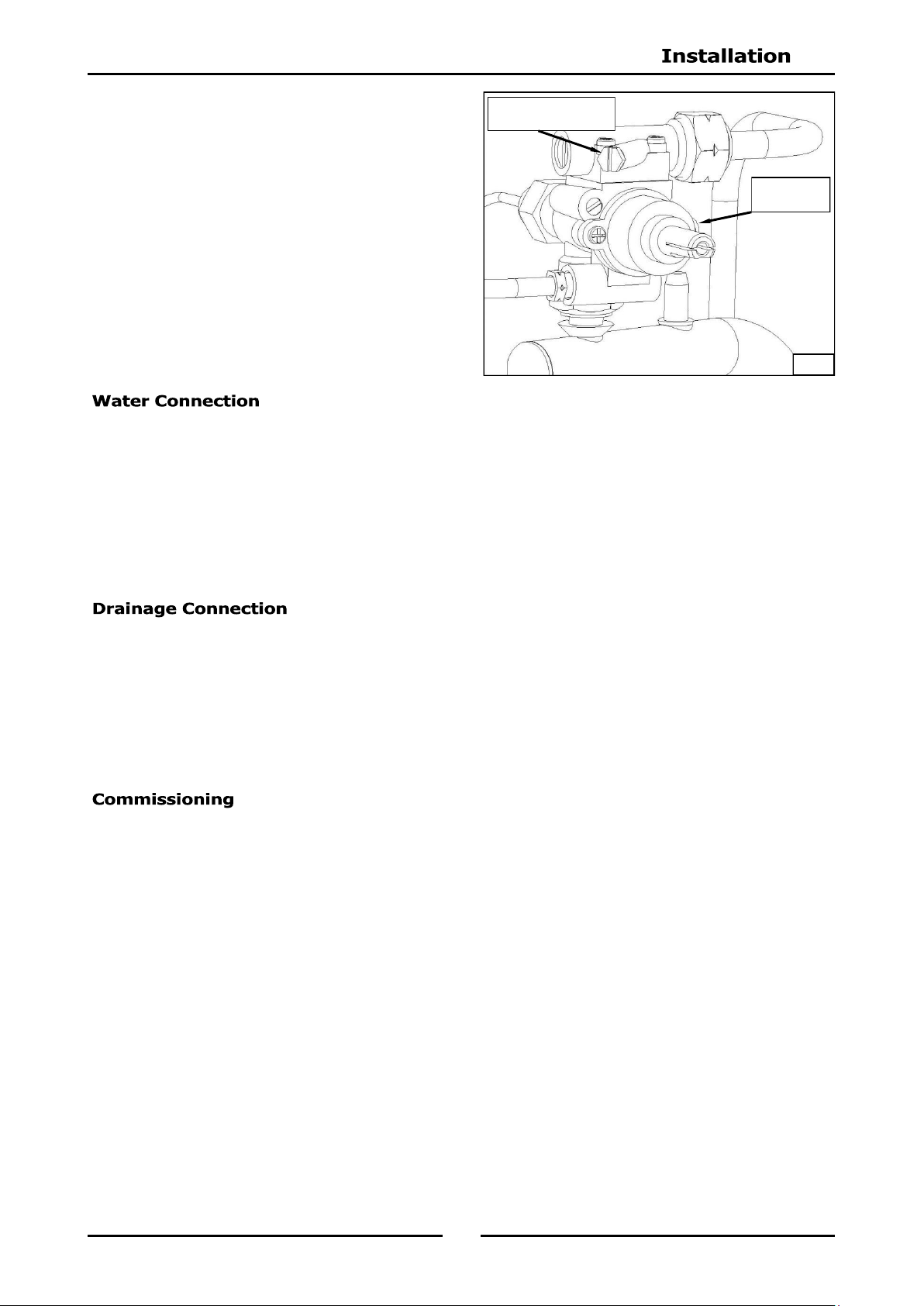
8. Verify operating pressure remains correct
9. Check pilot flame size. (Re-adjust if required
by changing pilot injector. Refer to Gas
Conversion Section).
This appliance is to be installed with adequate backflow protection and in compliance with local water
regulations in force.
A cold water supply must be connected to the water inlet connection (R
1
/
2
" BSP), located 152mm from
LH side, 556mm from rear and 151mm from floor.
Water inlet pressure must be as follows:-
Minimum water supply pressure 150kPa (22psi).
Maximum water supply pressure 550kPa (80psi).
Water is drained from appliance through a valve located behind the front control panel.
A waste water tundish must be fitted below appliance drain outlet. This should be a minimum of
127mm (5”) major diameter.
If required, drain outlet can be extended to exit above tundish. All drain piping must be with
materials suitable for conveying boiling water.
Drain connection is R1" BSP drain / overflow.
The following commissioning checks must be carried out before pasta cooker is handed over
for use, to ensure that unit operates correctly and operator(s) understand correct operating
procedure.
1. Before leaving the new installation;
a. Check the following functions in accordance with operating instructions specified in ‘Operation’
section of this manual.
Light Pilot Burner.
Light Main Burner.
b. Ensure each operator has been instructed in areas of correct lighting, operation, and shutdown
procedures for appliance.
2. This manual must be kept by the owner for future reference and a record of
Date of Purchase
,
Date
of Installation
and
Serial Number of Unit
recorded and kept w ith this manual. (These
details can be found on Rating Plate attached to inner R/H side of front access door
panel. Refer to Figure 1 in 'Installation' section).
NOTE: If for some reason it is not possible to get appliance to operate correctly, shut ‘Off’ gas
supply and contact supplier of this unit.
Fig 2
Gas Control
Valve
Burner Operating
Pressure Test Point
Loading ...
Loading ...
Loading ...