Loading ...
Loading ...
Loading ...
Basic Operation
DSO5000 Series Digital Storage Oscilloscope User Manual 43
Saved Settings
Saved Reference Waveforms
Display Contrast
Calibration Data
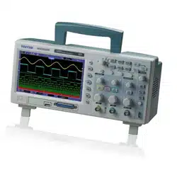
5.7 Multi-functional Knobs and Buttons
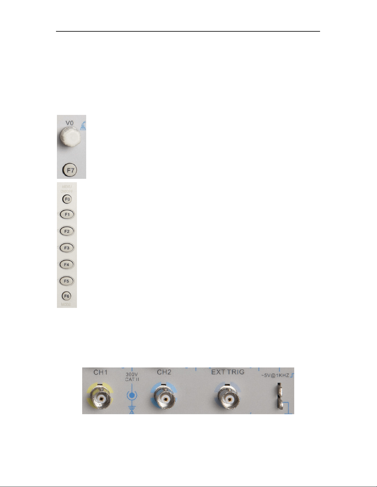
5.8 Signal Connectors
See the figure below to find the three signals connectors and a pair of metal electrodes at the
bottom of the oscilloscope panel.
1. CH1, CH2: Input connectors for waveform display, through which to connect and input the
signal to be measured.
V0: Multi-functional knob. Under different menu options, it supports select
ing menu
options (MEASURE), moving cursors and levels (Slope Trigger).
Press this knob to reset data (trigger holdoff, overtime of the overtime trigger
and
slope trigger), select menu options and so on. Easy to operate.
F7: Push this button in single-w
indow mode to switch between dotted line display
and cross display. Push it in dual-window mode to perform autocruise.
F0: Hide/Show but
ton. Push it to hide the menu options on the right side of the
screen and give a full screen display of waveforms
. Push it again to show the menu
options.
F1-F5: These five buttons are all multi-
functional. They are in charge of selecting
corresponding m
enu options on the screen in different menu modes. For example, in
the UTILITY menu, F1-F5 respectively correspond to ‘System Info’ – ‘Advance’.
F6: This functional button is mainly used to turn pages and confirm a selection, such
as ‘next page’, ‘previous page’, and ‘press F6 to confirm’
appearing when you push
Self Calibration option.
Loading ...
Loading ...
Loading ...