Loading ...
Loading ...
Loading ...
Basic Operation
DSO5000 Series Digital Storage Oscilloscope User Manual 29
Note: When you choose Normal Polarity, the trigger always occurs on negative-going sync
pulses. If the video signal contains positive-going sync pulses, use the Inverted Polarity
option.
Pulse Width Trigger
You can use it to trigger on aberrant pulses.
Options Settings Comments
Pulse
With Pulse highlighted, the trigger occurs on pulses that
meet the trigger condition (defined by the Source, When
and Set Pulse Width options).
Source
CH1
CH2
EXT
EXT5
Select the input source as the trigger signal.
When
=
≠
<
>
Select the trigger condition.
Set Pulse
Width
20ns to 10.0sec
With Set Pulse Width highlighted by pressing F4, turn the
multi-functional knob to set the pulse width.
Polarity
Positive
Negative
Select to trigger on positive or negative pulses.
Mode
Auto
Normal
Select the type of trigger. The Normal mode is best for
most pulse width trigger applications.
Coupling
AC
DC
HF Reject
LF Reject
Select the components of the trigger signal applied to the
trigger circuit.
More Switch between submenu pages.
Trigger When: The pulse width of the source must be ≥5ns so that the oscilloscope can detect the
pulse.
=
==
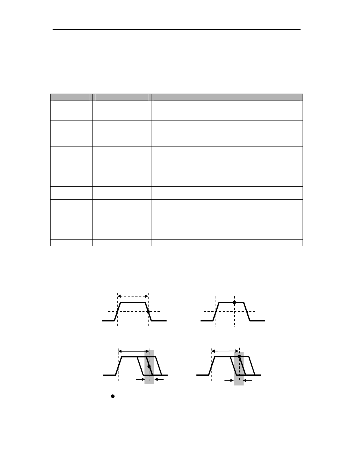
=, ≠: Within a ±5% tolerance, triggers the oscilloscope when the signal pulse width is equal to
Triggers when pulse is
equal to width setting ±5%
= Trigger Point
Threshold level
Triggers when pulse is
greater than width setting
Triggers when pulse is not
equal to width setting ±5%
Tolerance
Tolerance
Threshold level
Triggers when pulse is
less than width setting
Loading ...
Loading ...
Loading ...