
Loading ...
Loading ...
Loading ...
Basic Operation
DSO1000S Series HandHeld Oscilloscope User Manual 40
Vertical Coupling
DC (if GND was chosen before); AC for the video signal; otherwise,
unchanged
VOLTS
Adjusted
The Autoset function examines all channels for signals and displays corresponding waveforms.
Autoset determines the trigger source according to the following conditions.
If multiply channels get signals, the oscilloscope will use the channel with the lowest
frequency signal as the trigger source.
If no signals are found, the oscilloscope will use the lowest-numbered channel displayed
in Autoset as the trigger source.
If no signals are found and no channels are displayed, the oscilloscope will display and
use Channel 1 as the trigger source.
Sine Wave:
When you use the Autoset function and the oscilloscope determines that the signal is similar to a
sine wave, the oscilloscope displays the following options.
Sine Wave Options
Details
Multi-cycle Sine
Display multiple cycles that have appropriate vertical and
horizontal scales.
Single-cycle Sine
Set the horizontal scale to display about one cycle of the waveform.
Cancel
Let the oscilloscope recall the previous setup.
Square Wave or Pulse:
When you use the Autoset function and the oscilloscope determines that the signal is similar to a
square wave or pulse, the oscilloscope displays the following options.
Square Wave Options
Details
Multi-cycle
Display multiple cycles that have appropriate vertical and
horizontal scales.
Single-cycle
Set the horizontal scale to display about one cycle of the waveform.
The oscilloscope displays Min, Mean and Positive Width automatic
measurements.
Rising
Display the rising edge.
Falling
Display the falling edge.
Cancel
Let the oscilloscope recall the previous setup.
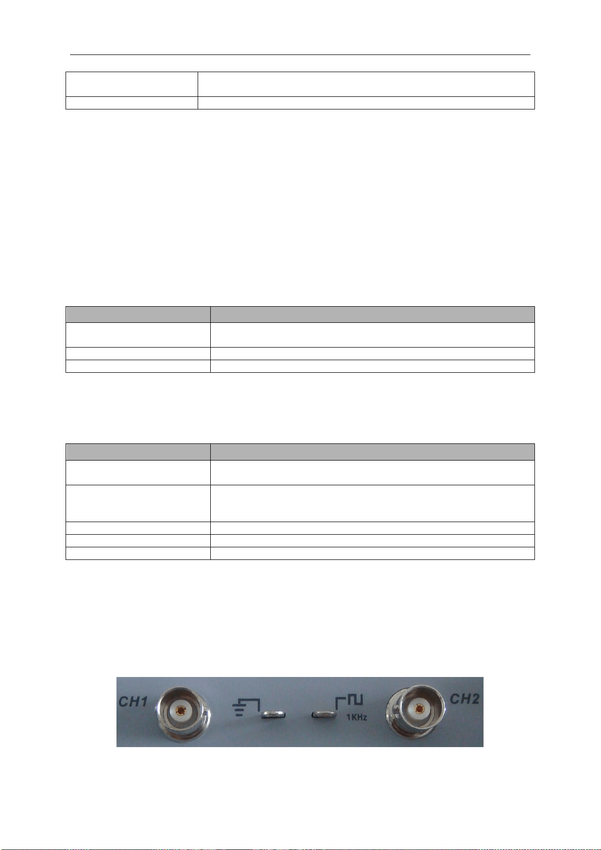
5.7 Signal Connectors
See the figure below to find the two signals connectors and a pair of metal electrodes at the
bottom of the oscilloscope panel.
1. CH1, CH2: Input connectors for waveform display, through which to connect and input the
Loading ...
Loading ...
Loading ...