Loading ...
Loading ...
Loading ...
Basic Operation
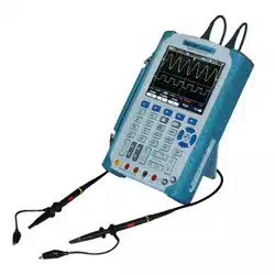
DSO1000S Series HandHeld Oscilloscope User Manual 17
7. Display of window’s position in data memory and data length.
8. Window Time Base
9. Operating Menu shows different information for different function keys.
10. Icon indicates channel coupling.
11. Level Range.
12. Icon indicates whether the waveform is inverted or not.
13. 20M Bandwidth Limit. If this icon lights up, it means the bandwidth limit is enabled, otherwise
disabled.
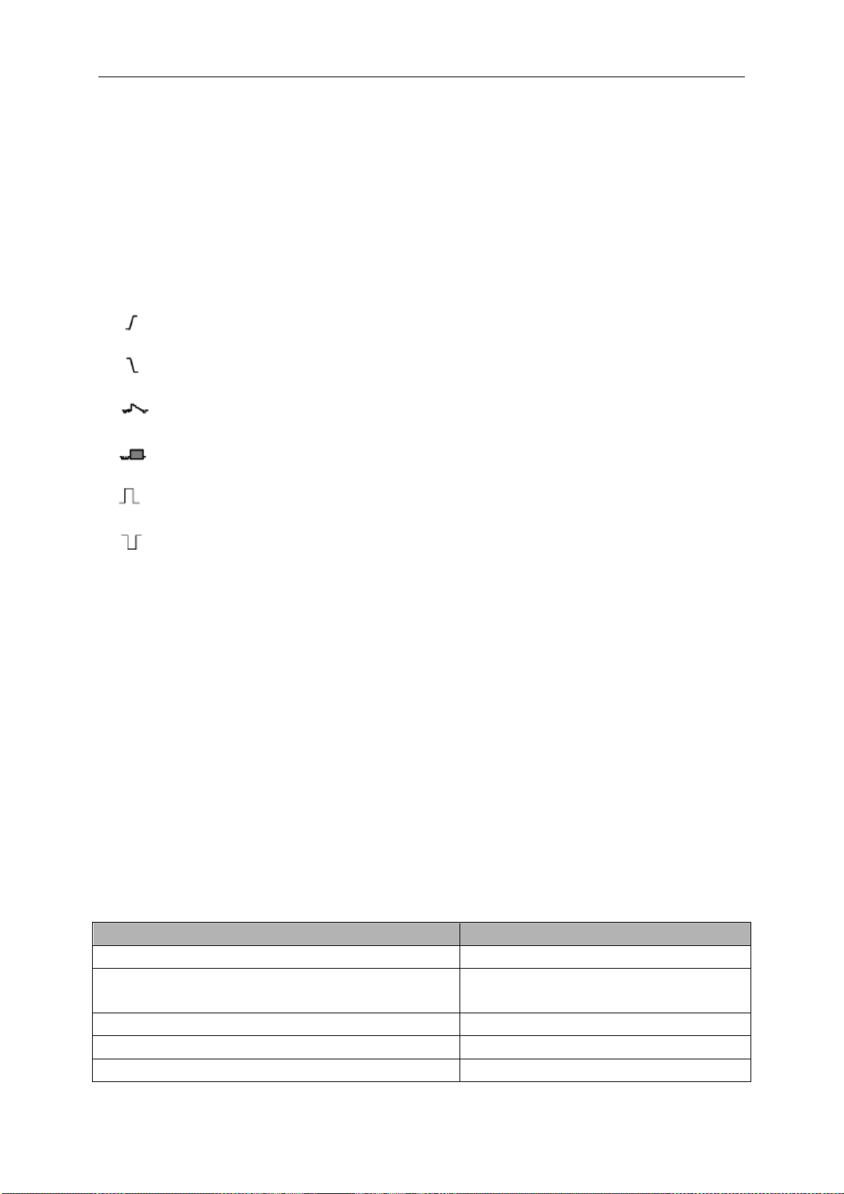
14. Trigger Type:
: Edge trigger on the rising edge.
: Edge trigger on the falling edge.
: Video trigger with line synchronization.
: Video trigger with field synchronization.
: Pulse Width trigger, positive polarity.
: Pulse Width trigger, negative polarity.
15. Trig Level.
16. Channel Marker
17. Window displays waveform.
5.1.1 XY Format
The XY format is used to analyze phase differences, such as those represented by Lissajous
patterns. The format plots the voltage on CH1 against the voltage on CH2, where CH1 is the
horizontal axis and CH2 is the vertical axis. The oscilloscope uses the untriggered Normal
acquisition mode and displays data as dots. The sampling rate is fixed at 1 MS/s.
The oscilloscope can acquire waveforms in YT format at any sampling rate. You may view the
same waveform in XY format. To perform this operation, stop the acquisition and change the
display format to XY.
The table below shows how to operate some controls in XY format.
Controls
Usable or not in XY format
CH1 VOLTS and VERTICAL POSITION controls
Set the horizontal scale and position
CH2 VOLTS and VERTICAL POSITION controls
Continuously set the vertical scale and
position
Reference or Math
Unusable
Cursors
Unusable
Autoset (display format reset to YT)
Unusable
Loading ...
Loading ...
Loading ...