

Technical Support and E-Warranty Certificate
www.vevor.com/support
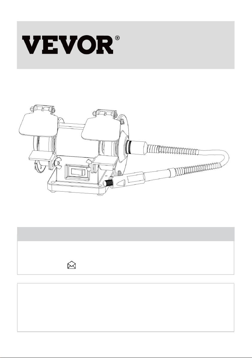
BENCH BUFFER POLISHER
USER MANUAL
We continue to be committed to offering tools at competitive prices. "Save Half", "Half Price",
or any other similar expressions used by us only represent an estimate of savings you might
benefit from buying certain tools with us compared to the major top brands and do not
necessarily mean to cover all categories of tools offered by us. You are kindly reminded to
verify carefully when placing an order with us if you are saving half in comparison with the top
major brands.

1
MODEL:TDS-75B
Have product questions? Need technical support? Please feel free to
contact us:
CustomerService@vevor.com
NEED HELP? CONTACT US!
This is the original instruction, please read all manual instructions carefully
before operating. VEVOR reserves a clear interpretation of our user manual. The
appearance of the product shall be subject to the product you received. Please
forgive us that we won't inform you again if there are any technology or software
updates on our product.
BENCH BUFFER
POLISHER

2
Read all safety warnings, instructions, illustrations and specifications provided with
this Bench grinder. Failure to follow all instructions listed below may result in electric
shock, fire and/or serious injury.
Save all warnings and instructions for future reference.
This manual provides critical safety instructions on the proper setup,
operation, maintenance, and service of this machine/tool. Save this
document, refer to it often, and use it to instruct other operators.
Failure to read, understand and follow the instructions in this manual
may result in fire or serious personal injury—including amputation,
electrocution, or death.
The owner of this machine/tool is solely responsible for its safe use.
This responsibility includes but is not limited to proper installation in
a safe environment, personnel training and usage authorization,
proper inspection and maintenance, manual availability and compre
hension, application of safety devices, cutting/sanding/grinding tool
integrity, and the usage of personal protective equipment.
The manufacturer will not be held liable for injury or property damage
from negligence, improper training, machine modifications or misuse.
Some dust created by power sanding, sawing, grinding, drilling, and
other construction activities contains chemicals known to the State
of California to cause cancer, birth defects or other reproductive
harm. Some examples of these chemicals are:
3
• Lead from lead-based paints.
• Crystalline silica from bricks, cement and other masonry products.
• Arsenic and chromium from chemically-treated lumber.
Your risk from these exposures varies, depending on how often you
do this type of work. To reduce your exposure to these chemicals:
Work in a well ventilated area, and work with approved safety equip
ment, such as those dust masks that are specially designed to filter
out microscopic particles.
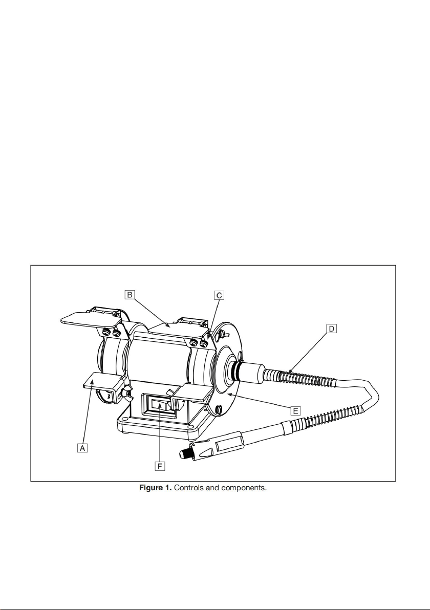
Controls & Components
Refer to Figure 1 and the following descriptions tobecome familiar with the basic
controls of this machine.
A. Tool Rest: Provides flat surface to rest workpiece during operations.
B. Safety Shield: Acts as a protective barrier against sparks during grinding
operations. This shield is not a substitute for personal protective equipment.
4
C. Spark Deflector: Reduces amount of sparks spraying back toward the
operator.
D. Rotating Shaft: Attaches to the right side of the grinder to provide rotary tool
functionality.
E. Wheel Guard: Prevents accidental contact with grinding wheel, and contains
sparks during grinding.
F. ON/OFF Switch: Turns motor ON when flipped to right; Turns motor OFF when
flipped to left.
3” MINI GRINDER/BUFFER WITH ROTATING SHAFT
Shipping Dimensions:
Weight........................................................................................................... 6 lbs.
Length x Width xHeight...................................................................... 10 x 8 x 7 in.
Main specifications:
Power Requirement.................................................... 120V, Single-Phase, 60 Hz
Full-Load Current
Rating............................................................................................................. 0.4A
Minimum Circuit
Size................................................................................................................. 15A
Connection Type................................................................................ Cord & Plug
Horsepower.............................................................................................. 1/14 HP
Phase............................................................................................... Single-Phase
Speed................................................................................................... 3600 RPM
Right Wheel Type....................................................................... Aluminum Oxide
Left Wheel Type............................................................................................ Wool
Wheel Bore.................................................................................................. 1/2 in.

5
SECTION 1: SAFETY
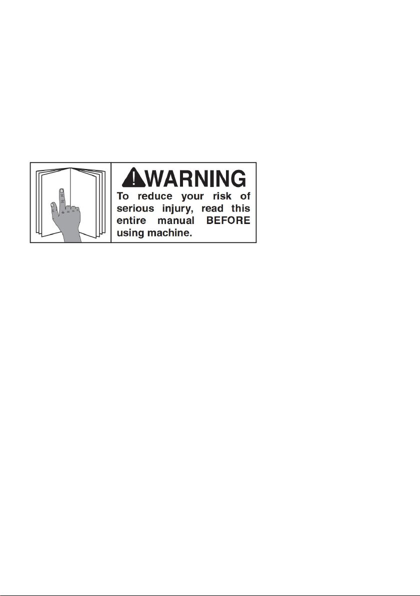
For Your Own Safety, Read Instruction Manual Before Operating This
Machine
The purpose of safety symbols is to attract your attention to possible
hazardous conditions. This manual uses a series of symbols and signal
words intended to convey the level of importance of the safety messages.
The progression of symbols is described below. Remember that safety
messages by themselves do not eliminate danger and are not a substitute
for proper accident prevention measures. Always use common sense and
good judgment.
Indicates an imminently hazardous situation which, if not avoided, WILL
result in death or serious injury.
Indicates a potentially hazardous situation which, if not avoided, COULD
result in death or serious injury.
Indicates a potentially hazardous situation which, if not avoided, MAY result
in minor or moderate injury. It may also be used to alert against unsafe
practices.
This symbol is used to alert the user to useful information about proper
operation of the machine.
Safety Instructions for Machinery

6
OWNER’S MANUAL. Read and understand this owner’s manual BEFORE using
machine.
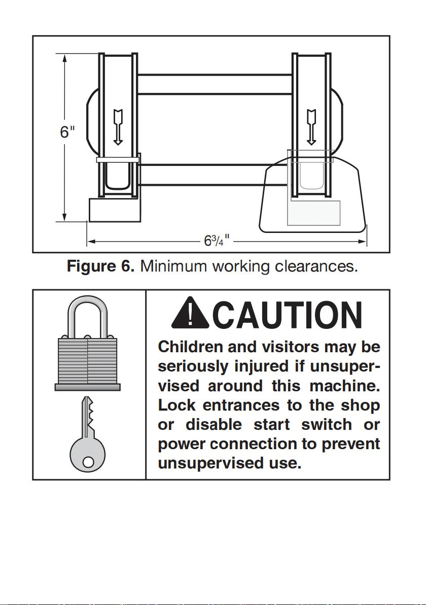
TRAINED OPERATORS ONLY. Untrained operators have a higher risk of being
hurt or killed. Only allow trained/supervised people to use this machine. When
machine is not being used, disconnect power, remove switch keys, or lock-out
machine to prevent unauthorized use—especially around children. Make
workshop kid proof!
DANGEROUS ENVIRONMENTS. Do not use machinery in areas that are wet,
cluttered, or have poor lighting. Operating machinery in these areas greatly
increases the risk of accidents and injury.
MENTAL ALERTNESS REQUIRED. Full mental alertness is required for safe
operation of machinery. Never operate under the influence of drugs or alcohol,
when tired, or when distracted.
ELECTRICAL EQUIPMENT INJURY RISKS. You can be shocked, burned, or
killed by touching live electrical components or improperly grounded machinery.
To reduce this risk, only allow qualified service personnel to do electrical
installation or repair work, and always disconnect power before accessing or
exposing electrical equipment.
DISCONNECT POWER FIRST. Always disconnect machine from power supply
BEFORE making adjustments, changing tooling, or servicing machine. This
prevents an injury risk from unintended startup or contact with live electrical
components.
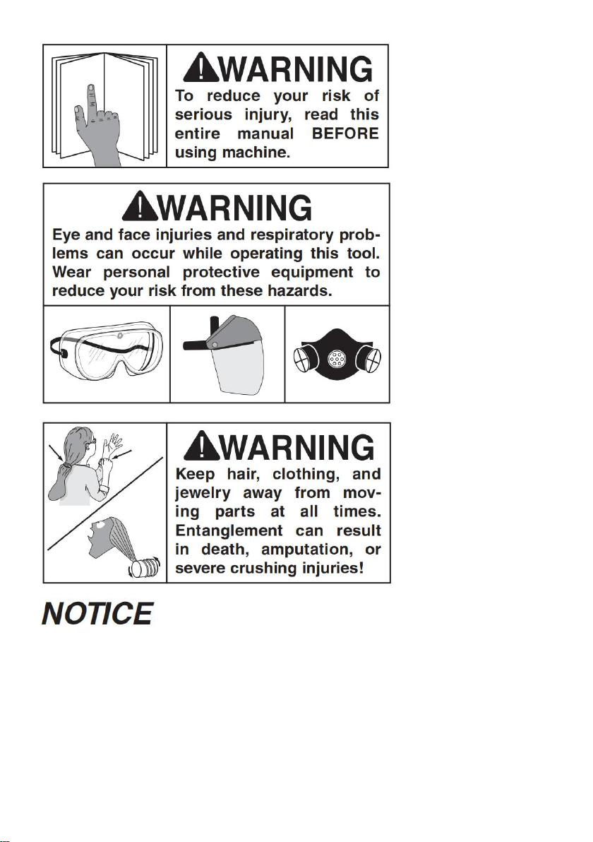
EYE PROTECTION. Always wear ANSI-approved safety glasses or a face shield
when operating or observing machinery to reduce the risk of eye injury or
blindness from flying particles. Everyday eyeglasses are NOT approved safety
glasses.
WEARING PROPER APPAREL. Do not wear clothing, apparel or jewelry that
can become entangled in moving parts. Always tie back or cover long hair. Wear
non-slip footwear to reduce risk of slipping and losing control or accidentally
contacting cutting tool or moving parts.

7
HAZARDOUS DUST. Dust created by machinery operations may cause cancer,
birth defects, or long-term respiratory damage. Be aware of dust hazards
associated with each workpiece mate rial. Always wear a NIOSH-approved
respirator to reduce your risk.
HEARING PROTECTION. Always wear hearing protection when operating or
observing loud machinery. Extended exposure to this noise without hearing
protection can cause permanent hearing loss.
REMOVE ADJUSTING TOOLS. Tools left on machinery can become dangerous
projectiles upon startup. Never leave chuck keys, wrenches, or any other tools on
machine. Always verify removal before starting!
USE CORRECT TOOL FOR THE JOB. Only use this tool for its intended
purpose—do not force it or an attachment to do a job for which it was not
designed. Never make unapproved modifications—modifying tool or using it
differently than intended may result in malfunction or mechanical failure that can
lead to personal injury or death!
AWKWARD POSITIONS. Keep proper footing and balance at all times when
operating machine. Do not overreach! Avoid awkward hand positions that make
workpiece control difficult or increase the risk of accidental injury.
CHILDREN & BYSTANDERS. Keep children and bystanders at a safe distance
from the work area. Stop using machine if they become a distraction.
GUARDS & COVERS. Guards and covers reduce accidental contact with moving
parts or flying debris. Make sure they are properly installed, undamaged, and
working correctly BEFORE operating machine.
FORCING MACHINERY. Do not force machine. It will do the job safer and better
at the rate for which it was designed.
NEVER STAND ON MACHINE. Serious injury may occur if machine is tipped or if
the cutting tool is unintentionally contacted.
STABLE MACHINE. Unexpected movement during operation greatly increases
risk of injury or loss of control. Before starting, verify machine is stable and mobile
base (if used) is locked.
USE RECOMMENDED ACCESSORIES. Consult this owner’s manual or the
manufacturer for recommended accessories. Using improper accessories will
increase the risk of serious injury.

8
UNATTENDED OPERATION. To reduce the risk of accidental injury, turn
machine OFF and ensure all moving parts completely stop before walking away.
Never leave machine running while unattended.
MAINTAIN WITH CARE. Follow all maintenance instructions and lubrication
schedules to keep machine in good working condition. A machine that is
improperly maintained could malfunction, leading to serious personal injury or
death.
DAMAGED PARTS. Regularly inspect machine for damaged, loose, or
mis-adjusted parts—or any condition that could affect safe operation. Immediately
repair/replace BEFORE operating machine. For your own safety, DO NOT
operate machine with damaged parts!
MAINTAIN POWER CORDS. When disconnect-ing cord-connected machines
from power,graband pull the plug-NOT the cord. Pulling the cordmay damage the
wires inside. Do not handlecord/plug with wet hands. Avoid cord damage
bykeeping it away from heated surfaces,high trafficareas, harsh chemicals, and
wet/damp locations.
EXPERIENCING DIFFICULTIES. If at any timeyou experience difficulties
performing the intend-ed operation, stop using the machine!
Additional Safety for Grinders
Serious injury or death can occur from impact injuries. Rotating grinding
wheels can easily remove skin, or entanglement/amputation injuries can
occur from being caught in moving parts or in-running pinch points. Flying
sparks can ignite explosive or flammable materials. To minimize risk of
getting hurt or killed, anyone operating machine MUST completely heed
hazards and warnings below.
SAFE MOUNTING & WORK AREA. An unsecured grinder may become
dangerously out of control during operation. Before use, verify grinder is FIRMLY
secured in a location free of explosive or flammable materials.

9
STARTING GRINDER. If a wheel is damaged, it will usually fly apart shortly after
start-up. To protect yourself, always stand to side of grinder when turning it ON
and allow it to run for at least one minute before standing in front of it.
VISUAL INSPECTION. Verify that grinding wheels are free of cracks, chips, or
dents in wheel surface before installing. Do not use wheel if it has any of these
problems or it could break apart during operation.
RING TEST. Perform a “ring test” on grinding wheels before installation to ensure
they are safe to use. A wheel that does NOT pass ring test may break or fly apart
during operation.
WHEEL SPEED RATING. Wheels operated at a faster speed than rated for may
break apart during operation. Before mounting a new wheel, be sure wheel RPM
rating is equal or higher than speed of grinder. Never use unmarked wheels.
VIBRATING WHEEL. Never use a wheel that vibrates. Replace wheel or shaft
bearings immediately.
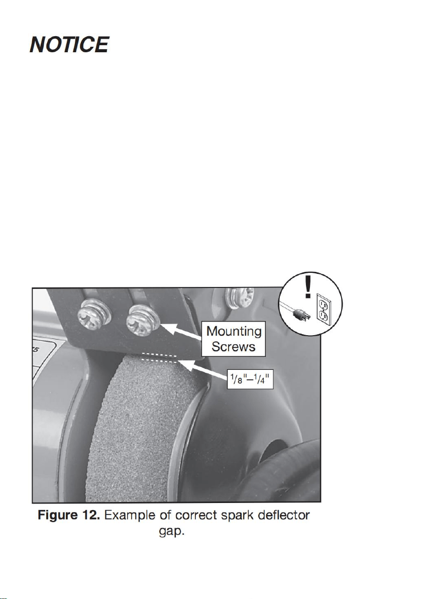
SPARK DEFLECTOR GAP. Keep gap between end of spark deflector and
grinding wheel between 1/8”and 1/4". If the gap is larger, excessive sparks and
abrasives can be expelled toward the operator.
SPINDLE NUT. Only tighten wheel spindle nut enough to drive wheel and prevent
slippage.
EYE SHIELDS. Place eye shields close to grinding wheel and re-adjust as wheel
wears down.
TOOL REST POSITION. If tool rest is too far away from wheel, workpiece may be
pulled down, causing loss of control and pulling your hand into grinding wheel.
Keep tool rest within 1 /8” from wheel when operating. Replace grinding wheel
when tool rest gap is wider than 1 /8” and no additional adjustment can be made.
HAND & WHEEL CONTACT. Keep a firm grip on workpiece and position your
hands a safe distance away when grinding. Anticipate when work
piece will heat up, and cool it before it becomes too hot to hold, or use an
appropriate clamp. Avoid wearing gloves as they may get caught in grinding
wheel and cause even more serious entanglement injuries.
WHEEL FLANGES. Only use flanges included with grinder when mounting
wheels. Other flanges may not properly secure wheel and cause an accident. Do
not use warped or damaged flanges, and always use paper discs (blotters)

10
between wheels and flanges to reduce risk of flanges cracking wheel when
tightened.
EYE, FACE, & LUNG PROTECTION. Grinding ejects small particles at a high
rate of speed. These particles can cause blindness, skin injuries or respiratory
damage. ALWAYS wear approved clothing, safety goggles, face shield, and a
respirator for type of grinding to be done.
SIDE & TOP GRINDING. Grinding on side of wheels can cause them to crack and
burst— unless wheel is rated for side grinding. Grinding on top of wheels greatly
increases risk of workpiece kickback. Always grind on downward part of wheel.
Additional Safety for Buffers
EYE/FACE PROTECTION. Always wear eye protection or a face shield when
operating the buffer.
LUNG PROTECTION. Always wear a respirator when using this machine.
Workpiece and buffing compound dust may cause allergies or long-term
respiratory health problems.
MOUNTING TO BENCH/STAND. An unsecured buffer may become dangerously
out of control during operation. Make sure buffer is FIRMLY secured to a
bench/stand before use.
CORRECT ACCESSORIES AND USE. The buffer is only designed for buffing
and polishing. Never exceed the maximum speed listed on each buffing/polishing
wheel.
WORKPIECE CONTROL. If you cannot hold small workpieces securely, do not
buff them with this machine. Secure them with clamps or similar jigs or use a
different buffer.
OPERATOR POSITION. Do not stand directly in front of thebuffer wheel when
turning the machine ON, or when buffing. Do not buff material at the rear of the
machine.
WORKPIECE SELECTION. Always inspect the condition of your workpiece. DO
NOT buff pieces with loose knots, large splinters, sharp edges, and DO NOT buff

11
knives, cable, chain or other potentially dangerous objects that may be grabbed
by the buffing wheel and thrown at the operator.
WORKPIECE FEED. Allow the wheel to reach full speed, then slowly ease the
workpiece into the buffing wheel, holding it in front of and slightly below the wheel
center. Do not place the workpiece on the top or sides of the buffing wheel and do
not place an edge or corner of the workpiece against the buffing wheel, or jam it
against the wheel. The workpiece may eject toward the operator or be torn from
the operato’rs hands, causing serious personal injury.
HAND/WHEEL CONTACT. Do not allow your hands to come into contact with the
buffing wheel. Abrasive accessories can remove skin fast. Keep a firm grip on the
workpiece and position your hands at a safe distance away when buffing. Avoid
wearing gloves as they may get caught in the buffing wheel and cause
entanglement inju ries.
ADJUSTMENTS/MAINTENANCE. Make sure your buffer is turned OFF,
disconnected from its power source, and all moving parts have come to a
complete stop before starting any inspection, adjustment, or maintenance
procedure.
AVOIDING ENTANGLEMENT. Keep long hair and loose clothing articles such as
sleeves, belts, and jewelry items away from the buffer.
Like all machinery there is potential danger when operating this bench
grinder. Accidents are frequently caused by lack of familiarity or failure to
pay attention. Use this bench grinder with respect and caution to lessen the
possibility of operator injury. If normal safety precautions are overlooked or
ignored, serious personal injury may occur.
No list of safety guidelines can be complete. Every shop environment is
different. Always consider safety first, as it applies to your individual
working conditions. Use this and other machinery with caution and respect.

12
Failure to do so could result in serious personal injury, damage to
equipment, or poor work results.
SECTION 2: POWER SUPPLY
Availability
Before installing the machine, consider the availability and proximity of the
required power supply circuit. If an existing circuit does not meet the requirements
for this machine, a new circuit must be installed. To minimize the risk of
electrocution, fire, or equipment damage, installation work and electrical wiring
must be done by an electrician or qualified service personnel in accordance with
all applicable codes and standards.
Electrocution, fire, or equipment damage may occur if machine is not
correctly grounded and connected to the power supply.
Full-Load Current Rating
The full-load current rating is the amperage a machine draws at 100% of the rated
output power. On machines with multiple motors, this is the amperage drawn by
the largest motor or sum of all motors and electrical devices that might operate
at one time during normal operations.
Full-Load Current Rating at 120V .... 0.4 Amps
The full-load current is not the maximum amount of amps that the machine will
draw. If the machine is overloaded, it will draw additional amps beyond
the full-load rating.
If the machine is overloaded for a sufficient length of time, damage, overheating,
or fire may result— especially if connected to an undersized circuit. To reduce the
risk of these hazards, avoid overloading the machine during operation and make

13
sure it is connected to a power supply circuit that meets the specified circuit
requirements.
Serious injury could occur if you connect machine to power before
completing setup process. DO NOT connect to power until instructed later
in this manual.
120V Circuit Requirements
This machine is prewired to operate on a power supply circuit that has a verified
ground and meets the following requirements:
Nominal Voltage ........................................120V
Cycle..........................................................60 Hz
Phase........................................... Single-Phase
Power Supply Circuit ......................... 15 Amps
A power supply circuit includes all electrical equipment between the breaker box
or fuse panel in the building and the machine. The power supply circuit used for
this machine must be sized to safely handle the full-load current drawn from the
machine for an extended period of time. (If this machine is connected to a circuit
protected by fuses, use a time delay fuse marked D.)
For your own safety and protection of property, consult an electrician if you
are unsure about wiring practices or electrical
codes in your area.
Note: Circuit requirements in this manual apply to a dedicated circuit—where only
one machine will be running on the circuit at a time. If machine will be connected
to a shared circuit where multiple machines may be running at the same time,
consult an electrician or qualified service personnel to ensure circuit is properly
sized for safe operation.
14
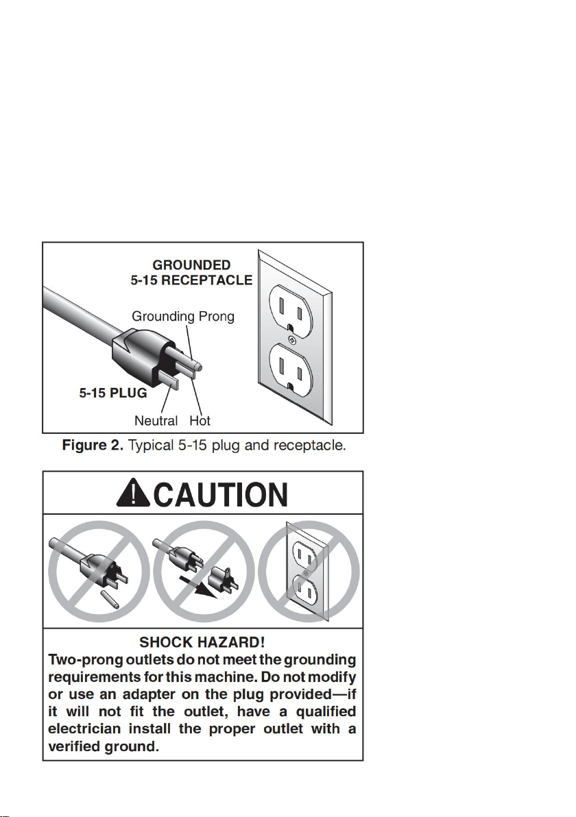
Grounding & Plug Requirements
This machine MUST be grounded. In the event of certain malfunctions or
breakdowns, grounding reduces the risk of electric shock by providing a path of
least resistance for electric current. This machine is equipped with a power cord
that has an equipment-grounding wire and a grounding plug. Only insert plug into
a matching receptacle (outlet) that is properly installed and grounded in
accordance with all local codes and ordinances. DO NOT modify the provided
plug!

15
Improper connection of the equipment-grounding wire can result in a risk of
electric shock. The wire with green insulation (with or without yellow stripes) is the
equipment-grounding wire. If repair or replacement of the power cord or plug is
necessary, do not connect the equipment-grounding wire to a live (current
carrying) terminal.
Check with a qualified electrician or service personnel if you do not understand
these grounding requirements, or if you are in doubt about whether the tool is
properly grounded. If you ever notice that a cord or plug is damaged or worn,
disconnect it from power, and immediately replace it with a new one.
Extension Cords
We do not recommend using an extension cord with this machine. If you must use
an extension cord, only use it if absolutely necessary and only on a temporary
basis.
Extension cords cause voltage drop, which can damage electrical components
and shorten motor life. Voltage drop increases as the extension cord size gets
longer and the gauge size gets smaller (higher gauge numbers indicate smaller
sizes).
Any extension cord used with this machine must be in good condition and contain
a ground wire and matching plug/receptacle. Additionally, it must meet the
following size requirements:
Minimum Gauge Size ...........................16 AWG
Maximum Length (Shorter is Better).......50 ft.
SECTION 3: SETUP
16
Needed for Setup
The following are needed to complete the setup process:(Not included in box)
Description Qty
• Safety Glasses ........................................... 1
• Solvent/Cleaner.......................................... 1
• Shop Rags.................................................. 1
• Phillips Screw Driver #2 ............................. 1
Unpacking
This machine was carefully packaged for safe transport. When unpacking,
separate all enclosed items from packaging materials and inspect them for
shipping damage.
IMPORTANT: Save all packaging materials until you are completely satisfied with
the machine and have resolved any issues. You MUST have the original
packaging to file a freight claim. It is also extremely helpful if you need to return
your machine later.
Inventory
The following is a list of items shipped with your machine. Before beginning setup,
lay these items out and inventory them. If any non-proprietary parts are missing
17
(e.g. a nut or a washer), we will gladly replace them; or for the sake of expediency,
replacements can be obtained at your local hardware store.
If you cannot find an item on this list, carefully check around/inside the
machine and packaging materials. Often, these items get lost in packaging
materials while unpacking or they are pre-installed at the factory.
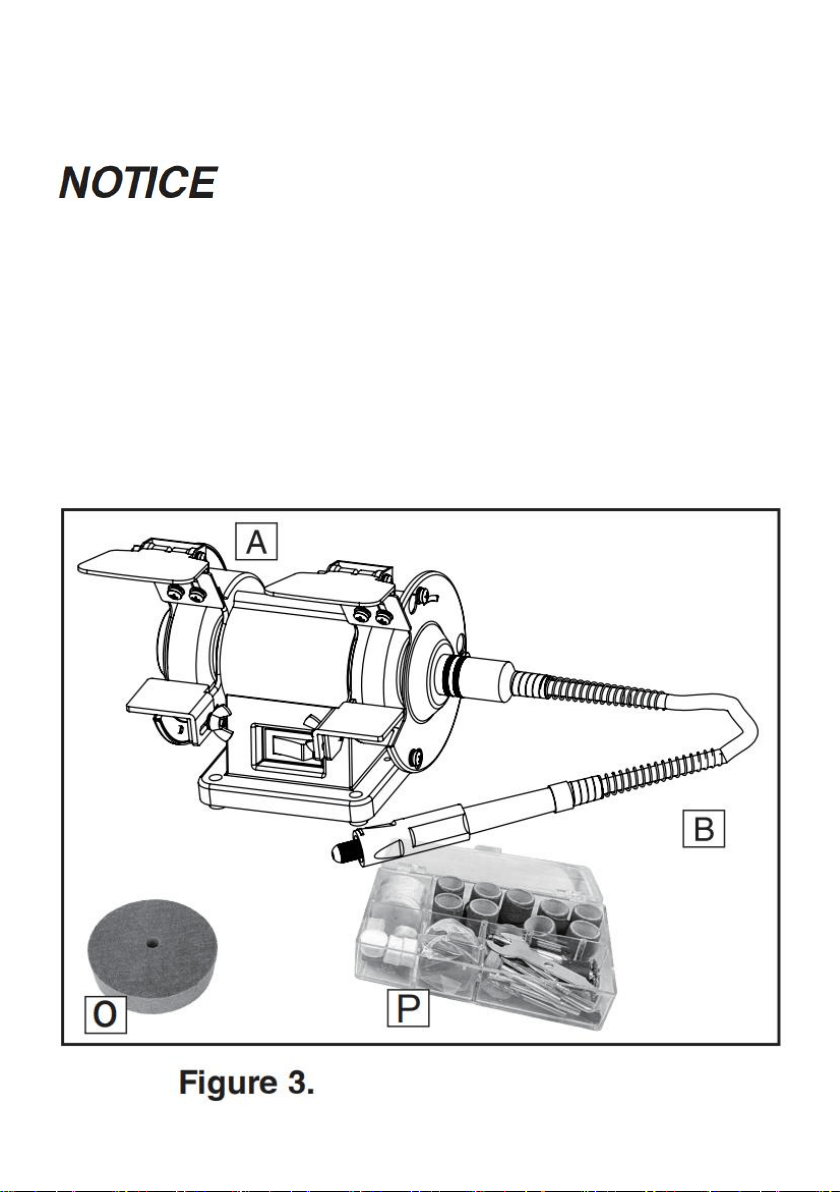
Box 1 (Figures 3–5) Qty
A. Grinder ....................................................... 1
B. Rotating Shaft............................................. 1
O. Fiber wheel................................................. 1
P. Kit box ........................................................ 1
18
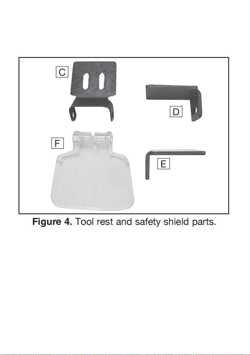
C. Spark Deflector............................................ 2
D. Tool Rest (Left) ........................................... 1
E. Tool Rest (Right) ......................................... 1
F. Safety Shield ................................................2
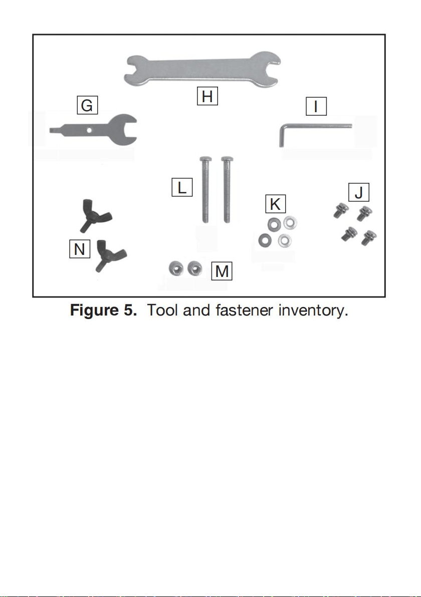
G. Collet Wrench............................................. 1
H. Open-End Wrench 10mm x 7mm............... 1
I. Pin Wrench................................................... 1
J. Phillips Head Screws M4-.7 x 8................... 4
K. Flat Washers 4mm ..................................... 4
L. Phillips Head Screw M4-.7 x 40................... 2
M. Flange Nut M4-.7........................................ 2
N. Wing Bolts M4-.7 x 10................................. 2
19
Site Considerations
Workbench Load
Refer to the Machine Data Sheet for the weight and footprint specifications of
your machine. Some workbenches may require additional reinforcement to
support the weight of the machine and workpiece materials.
Placement Location
Consider anticipated workpiece sizes and additional space needed for auxiliary
stands, work tables, or other machinery when establishing a location for this
machine in the shop. Below is the minimum amount of space needed for the
machine.
20
Bench Mounting
Number of Mounting Holes ............................ 4
Diameter of Mounting Hardware................ 3 /16"
21
The base of this machine has mounting holes that allow it to be fastened to a
workbench or other mounting surface to prevent it from moving during operation
and causing accidental injury or damage.
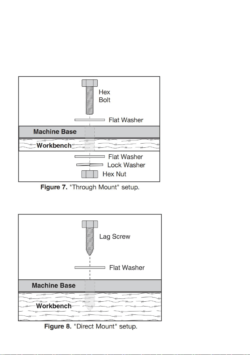
The strongest mounting option is a "Through Mount" (see example below) where
holes are drilled all the way through the workbench—and hex bolts, washers, and
hex nuts are used to secure the machine in place.
Another option is a "Direct Mount" (see example below) where the machine is
secured directly to the workbench with lag screws and washers.
22
Assembly
To assemble grinder:
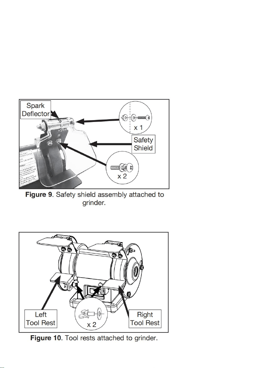
1. Attach safety shield to spark deflector using (1) M4-.7 x 40 Phillips head screw,
(1) 4mm flat washer, (1) M4-.7 flange nut, as shown in Figure 9.
2. Attach safety shield assembly to right side of grinder using (2) M4-.7 x 8 Phillips
head screws with captive flat and lock washers, as shown in Figure 9.
3. Attach each tool rest to grinder using (2) 4mm flat washers and (2) M4-.7 x 10
wing bolts, as shown in Figure 10.
23
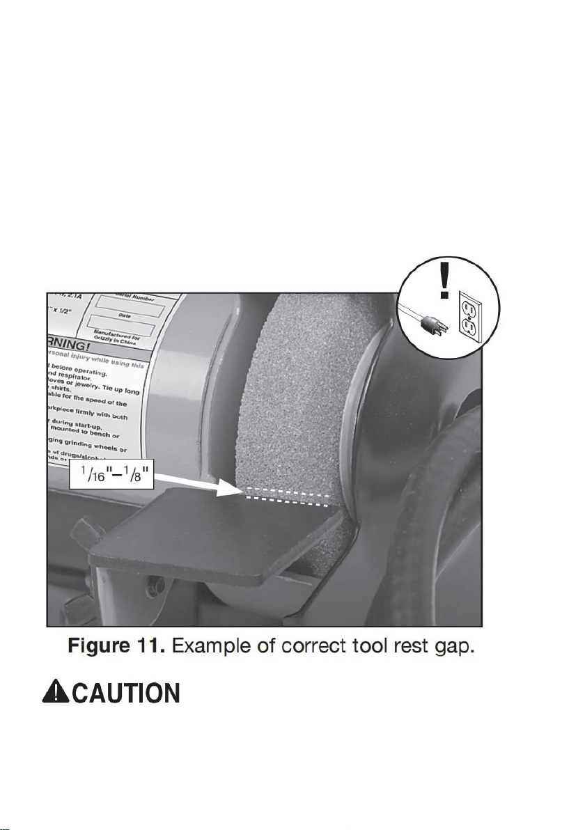
Tool Rest Adjustment
The tool rest stabilizes the workpiece when grinding. It must always be positioned
correctly when using the grinder to avoid the workpiece or the
operator's hands being pulled into grinding wheel.
As the grinding wheel wears, loosen the wing bolt and adjust the tool rest closer to
the grinding wheel to maintain a gap of 1/16" –1/8" (see Figure 11), then retighten
the wing bolt. If the gap reaches 1/8" and no additional adjustments can be made,
replace the grinding wheel.
NEVER grind without tool rest in place and properly positioned. "Free hand"
grinding or too large of a gap between wheel and tool rest increases risk of
kickback, which may lead to serious injury.
24
Some grinding wheels must be replaced before spark deflector or tool rest
reach their final adjustment. As diameter of a grinding wheel is reduced, so
is available surface speed. Grinding under these conditions can lead to
faster abrasive loss and poor grinding results. Always follow wheel
manufacturer's directions.
Spark Deflector Adjustment
The spark deflector prevents sparks from showering the top of the workpiece and
the operator's hands. As the wheel wears, loosen the mounting screws shown in
Figure 12, and adjust the spark deflector closer to the grinding wheel to maintain
a gap of 1 /8" –1 /4", then re-tighten mounting screws. If the gap reaches 1 /4" and
no additional adjustments can be made, replace the grinding wheel.

25
Test Run
Once assembly is complete, test run the machine to ensure it is properly
connected to power and safety components are functioning correctly. If you find
an unusual problem during the test run, immediately stop the machine, disconnect
it from power, and fix the problem BEFORE operating the machine again. The
Troubleshooting table in the SERVICE section of this manual can help.
Serious injury or death can result from using this machine BEFORE
understanding its controls and related safety information. DO NOT operate,
or allow others to operate, machine until the information is understood.
DO NOT start machine until all preceding setup instructions have been
performed. Operating an improperly set up machine may result in
malfunction or unexpected results that can lead to serious injury, death, or
machine/property damage.
To test run machine:
1. Clear all setup tools away from machine.
2. Connect machine to power supply.
3. Turn machine ON, verify motor operation, and then turn machine OFF. The
motor should run smoothly and without unusual problems or noises.
Note: A small amount of vibration during operation is normal.
SECTION 4: OPERATIONS
26
If you are not experienced with this type of machine, WE STRONGLY
RECOMMEND that you seek additional training outside of this manual. Read
books/magazines or get formal training before beginning any projects.
Regardless of the content in this sec tion, will not be held liable for
accidents caused by lack of training.
To complete a typical operation, the operator does the following:

27
1. Examines workpiece to make sure it is suitable for grinding or buffing.
2. Selects correct wheel for type of operation, inspects wheel, performs a "ring
test" (on grinding wheel), and installs wheel.
3. Verifies/adjusts tool rest position so it is perpendicular to wheel and gap is 1
/16" to 1 /8"; verifies/adjusts spark deflector so wheel gap is 1 /8" to 1 /4".
4. Positions safety shield for safe grinding.
5. Ensures that ON/OFF switch is in OFF position, and connects grinder to power.
6. Puts on personal protective equipment.
7. Stands aside, starts grinder, and allows it to reach full speed and operate for at
least one minute to ensure grinding wheel does not fly apart from centrifugal force
of rotation.
8. Places workpiece on tool rest and positions it for grinding or buffing.
9. Operator gradually feeds workpiece into wheel and moves workpiece left and
right.
10. After grinding operation is complete, quenches workpiece as required to
prevent surface hardening or temper loss.
11. Stops bench grinder.
Workpiece Inspection
Some workpieces are not suitable for grinding on a bench grinder. Before
grinding, inspect all workpieces for the following:
• Hard Workpiece: Workpieces that are made of stone, carbide, stainless steel,
ceramics, glass, or have hardened welds will wear out most general-grade
grinding wheels quickly. If hard materials are to be ground, you must install the
correct type of grinding wheel.
• Soft Workpiece: Workpieces that are made of aluminum, brass, lead, and other
nonferrous metals will load up in the grinding wheel and render the abrasive
useless. Grinding wood, plastics, rubber, fiberglass, or other soft materials can
also cause the same problem and lead to the wheel overheating and possibly
bursting during use if ignored. To restore a loaded grinding wheel surface, redress
with a dressing tool.

28
• Flexible/Unstable Workpiece: Grinding on the side or the ends of cable, chain,
or round workpieces creates the hazard of workpiece twist or grab, leading to
entanglement with the wheel or shaft. This hazard must be avoided.
• Loose Parts: Make sure that the workpiece is free of any parts like springs, pins,
balls, or other components that may loosen or dislodge during grinding, and hit
the operator.
• Strength: Make sure that the workpiece is strong enough to be ground. Should
it break, the broken piece may dig into the wheel and cause kickback or severe
injury.
Electrical system is not waterproof. DO NOT use this grinder with a liquid
cooling system required for wet grinding wheel operations. Ignoring this
warning can lead to electrocution or machine damage.
Wheel Selection
The Model only accepts Type 1 wheels with a 1 /2" bore.
Aluminum oxide and silicon carbide wheels are marked in a somewhat uniform
manner by all the major manufacturers. Understanding these markings will help
you understand the capabilities of various wheels. Always refer to the manufac
turer’s grinding recommendations when selecting a wheel for your project.
The basic format for wheel numbering is:
The Prefix is the manufacturer’s designation for a particular wheel type (eg. Type
1 wheels).
The most common Abrasive Types used are A for Aluminum Oxide, C for Silicon
Carbide, and occasionally SG for Seeded Gel.

29
The Grit Size is a number that refers to the size of the abrasive grain in the wheel.
The lower the number, the coarser the wheel. Ten is a very coarse wheel for
roughing and 220 is usually the upper range for fine finish work.
Grade is an indication of the hardness of the wheel—“A” being the softest and “Z”
being the hardest.
Bond Type refers to the type of bonding material used to hold the abrasive
material. Most general purpose wheels will have a “V” indicating Vitrified Clay is
used. Vitrified Clay provides high strength and good porosity. The other common
bond type is “B” for resin where synthetic resins are used. These are used to grind
cemented carbide and ceramic materials.
Note: There may be other numbers inserted that have meaning for a particular
type of wheel. Refer to the manufacturer’s technical data for a complete
explanation.
Wheel Inspection
Before mounting a new grinding wheel, it must be inspected. Do not assume that
a wheel is in sound condition just because it is new—often damage can occur in
shipping, with age, or with exposure to moisture.
First, do a Visual Inspection. Look for any cracks, chips, nicks or dents in the
surface of the wheel. If you see any of these, DO NOT use the wheel.
Second, do a Ring Test. This test will give you an indication of any internal
damage that may not be obvious during a visual inspection.
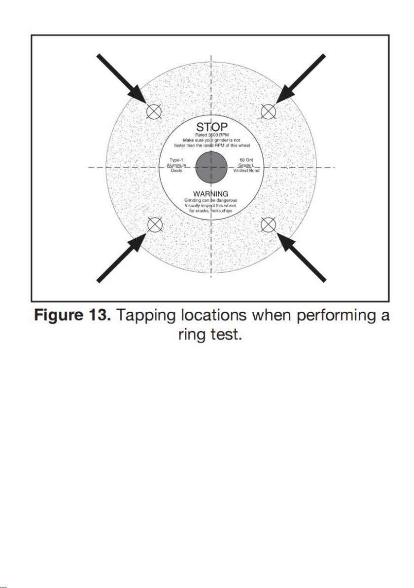
To perform ring test:
1. Make sure grinding wheel you test is clean and dry; otherwise, you may get
false results.
2. If size permits, balance grinding wheel with your finger in mounting hole. If this
is not possible, hang wheel in air with a piece of cord or string looped through
mounting hole in center.
3. At spots shown in Figure 13, gently tap grinding wheel with a light non-metallic
device such as handle of a screwdriver or a wooden mallet.
Note: Finding exact spot to tap will take several attempts.
30
4. An undamaged grinding wheel will emit a clear metallic ring or “ping” sound in
each of these spots. A damaged grinding wheel will respond with a dull thud that
has no clear tone.
— If you determine from ring test that grinding wheel is damaged, DO NOT use it!
Wheel Dressing
Depending on the type of grinding you do, the grinding wheel may require periodic
dressing.
There are several different types of wheel dressing devices available on the
market (see Page 25 for examples). Dressing restores the abrasive quality
of the wheel surface and brings the wheel edge back to a square form.

31
Refer to the instructions that accompany your dressing accessory for complete
details on how to properly dress the wheel.
Always adjust tool rest and spark deflector after dressing or replacing
grinding wheel. Failure to do so could lead to workpiece kickback and
injury.
Wheel Care
When grinding, your safety depends, to a large degree, on the condition of the
wheel. A wheel in poor condition presents the possibility of breaking apart during
rotation and injuring the operator and others in the area.
Tips to help you avoid breaking the wheel:
• Always transport, store and handle wheels with care. Wheels may be damaged
if they are dropped or if heavy objects are stacked on them.
• Select the right grinding wheel for the job. DO NOT grind material inappropriate
for the wheel type.
• Only use wheels that are rated for the RPM of the tool grinder.
• Mount the wheel properly (see Installing/ Removing Grinding Wheel on this
page).
• Do not push the tooling into the grinding wheel with such force that it causes the
grinder to bog down. And do not apply pressure to stop the wheel after turning the
grinder OFF.
• Dress the wheel when necessary. Do not allow it to become glazed (see Wheel
Dressing on Page 18).
• Do not store wheels in damp or wet locations.
• Do not overtighten the nut when mounting the wheel.
• Do not leave the wheel mounted when machine is not in use.
Installing/Removing Grinding Wheel
32
ALWAYS visually inspect and perform a “ring test” on a wheel before
installing. DO NOT use damaged wheels!
To install/remove grinding wheel:
1. DISCONNECT MACHINE FROM POWER!
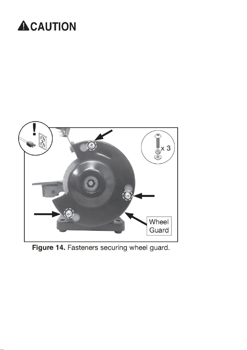
2. To remove outer guard, loosen (3) M4-.7 x 10 Phillips head screws with captive
flat and lock washers holding wheel guard in place (see Figure 14).
3. Remove wheel guard (see Figure 14) by twisting guard clockwise until screws
align with access holes.
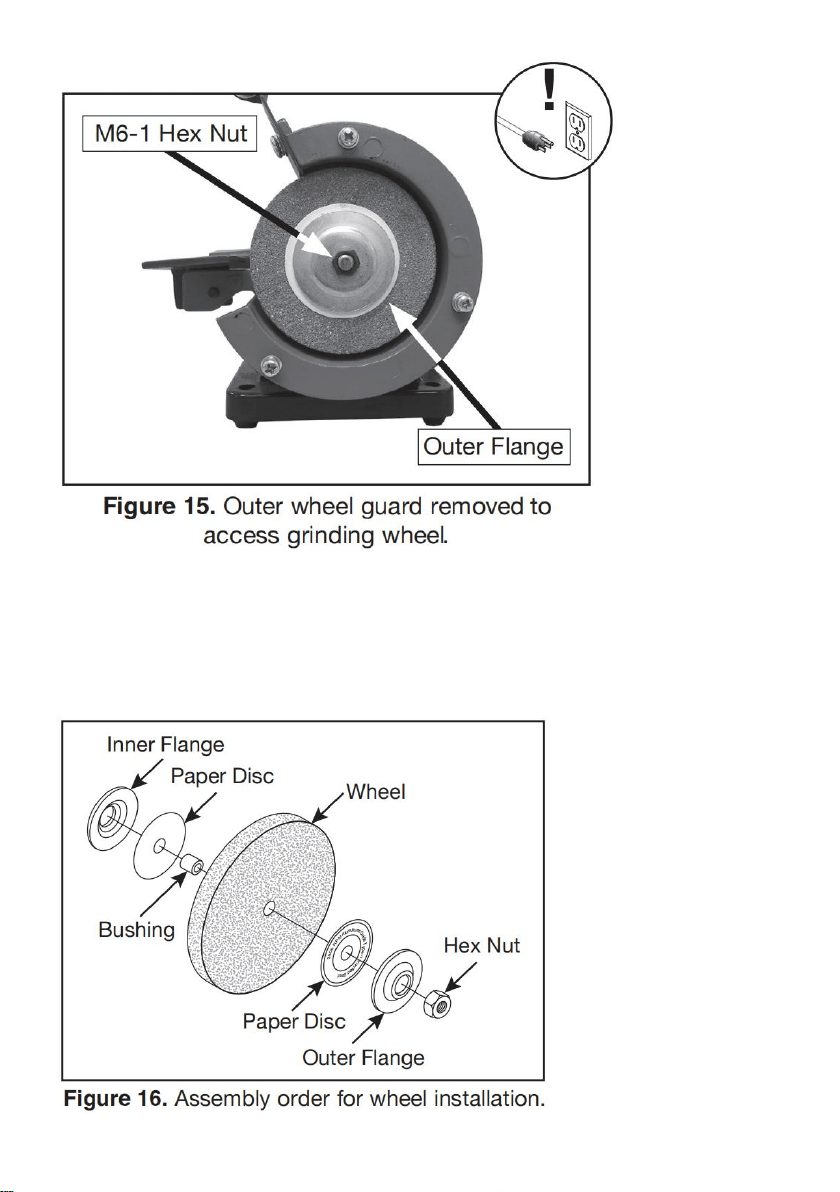
4. Remove M6-1 hex nut (see Figure 15) .
Tip: Hold grinding wheel with free hand tostop spindle from turning while
removing hexnut.
Note: Spindle on left side of grinder has left-hand threads. Turn it clockwise to
loosen.
33
5. Remove outer wheel flange and paper disc(see Figure 16) .
6. Remove grinding wheel and bushing fromspindle (see Figure 16). Take note of
paperor fiber disc between wheel flanges andwheel. These cushion the pressure
of thewheel flanges and help distribute pressuremore evenly. They also help
reduce damageto the flanges.

34
NEVER install grinding wheel on spindle without paper or fiber discs
between whee land flange. Not using discs can put stress on wheel, causing
it to crack and possibly fall apart.
7. Verify the flatness of the inner and outer flanges by placing them on a level
surface.lf either flange is warped or damaged,replace it.
Warped wheel flanges can contribute to grinding wheel breaking and flying
apart.Never use warped wheel flanges. Always check flanges before
re-installing grinding wheel.
8. Mount new grinding wheel and bushing in order shown in Figure 16. Tighten
M6-1 hex nut snugly but do not over-tighten. Over-tightening can stress and crack
wheel.
9. Re-assemble outer wheel guard using hard-ware removed in Step 2.
10. While standing away from line of rotation,turn grinder ON and run new
grinding wheel for at least 1-2 minutes before standing in front of it. This helps
protect you if the wheel has internal damage that will cause it to fly apart from the
centrifugal force of rotation.
- If grinder runs smoothly, grinding wheel may now be used.
- If wheel appears to wobble, grinder vibrates excessively, or any other unsafe
condition appears with new wheel, stop grinder and refer to Troubleshooting on
Page 29.
Buffing
Below are some quick tips for getting the most out of your buffing wheel.
Remember, there is no substitute for experience. Learning how to hold the
workpiece, how much pressure to apply, how to move the workpiece against the

35
wheel, and how much compound to use requires a certain amount of
trial-and-error.
• Thoroughly clean all parts you plan to buff. Dirt, oil, rust, paint, or other film must
be removed chemically or with water. Make sure to dry off parts with a rag after
cleaning.
• Apply buffing compounds in small amounts at a time. Apply paste-type
compounds with a wand or directly to the part. For wax-based polishing stick-type
compounds, press the compound on the wheel for a couple of seconds while the
machine is running. Avoid using too much compound.
• Put your workpiece under the wheel when you are loading the compound on the
buffing wheel. This way, you will catch any compound that would normally be
wasted on the floor.
• To begin buffing, place your workpiece on the tool rest and slowly feed it into the
buffing wheel. Hold the workpiece tightly at all times while buffing. Placing one
hand near the contact point will give you better control.
• Keep buffing wheels raked out before each use and when buildup gets heavy
during use. Raking means to clean the buffing wheels with a wheel rake to
remove built-up compounds and metal particles. ALWAYS use light pressure
when raking wheels!
• Do not mix two different compounds on the same wheel. For best results, use a
separate wheel for each compound.
• Wear safety equipment when buffing. If the buffer forces the workpiece out of
your hand, be prepared for it to come flying at you! Wear safety glasses or a face
shield and a heavy leather apron. Also, wear a dust mask to protect your lungs
from microscopic particulate that will be flying off the wheel.
Always hold workpiece firmly against tool rest while buffing. Failure to do
so may cause workpiece to be thrown from operator's hands, causing
personal injury.
36
Installing/Removing Buffing Wheel
This grinder has a left and right shaft to provide the option of mounting grinding or
buffing acces sories, depending on your application.
Safety shield must always be installed for grinding operations. Failure to do
so may result in serious personal injury.
To install/remove buffing wheel:
1. DISCONNECT MACHINE FROM POWER!
2. Loosen (3) M4-.7 X 10 Phillips head screws with captive flat and lock washers
holding wheel guard in place (see Figure 14 on Page 19).
3. Remove outer guard (see Figure 14 on Page 19).
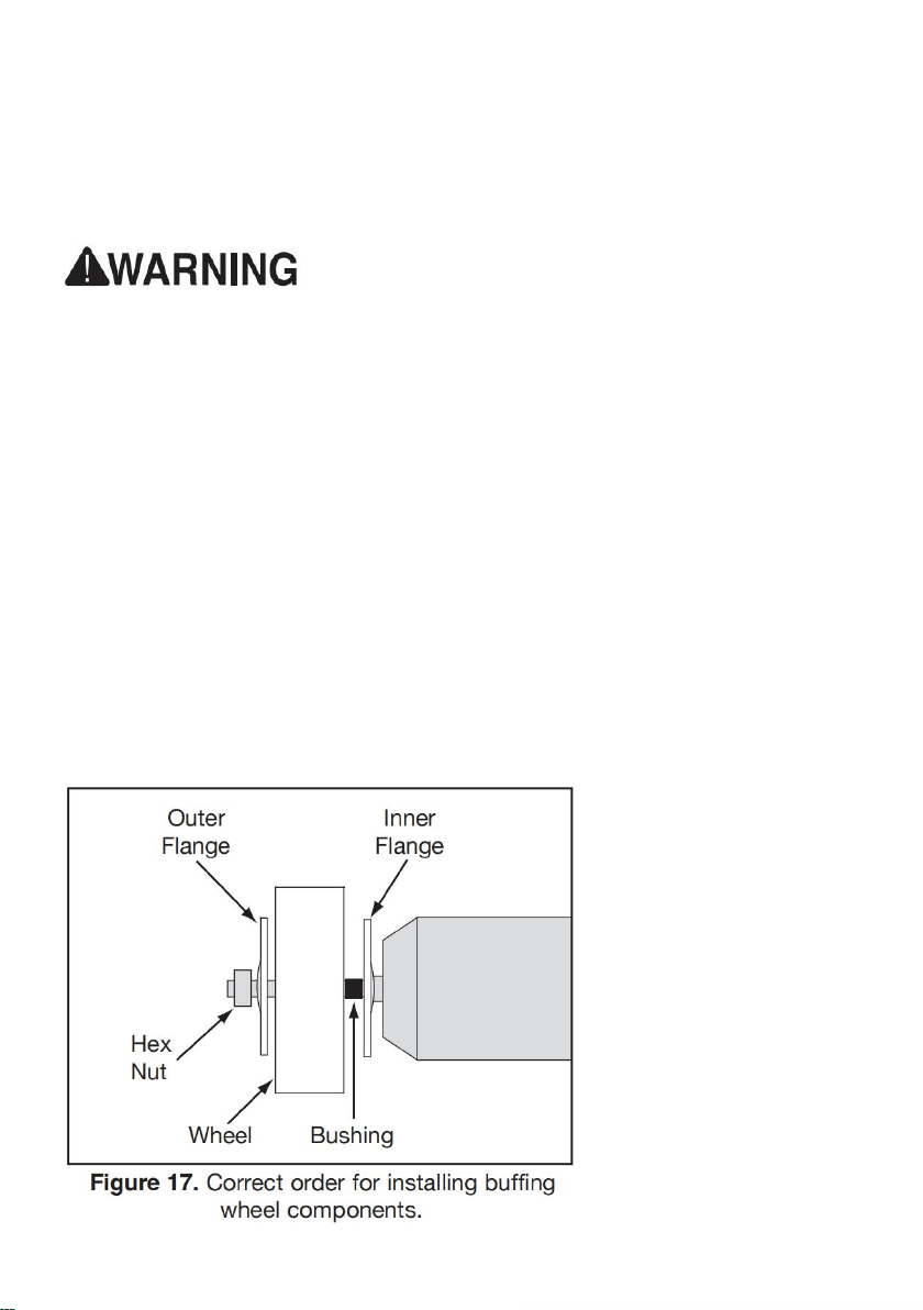
4. Remove M6-1 hex nut (see Figure 17).
Note: Spindle on left side of grinder has lefthand threads. Turn clockwise to
loosen.
5. Remove outer flange, buffing wheel, and bushing from spindle (see Figure 17).
6. Install new buffing wheel, bushing, and wheel flange (see Figure 17). Then
re-install M6-1 hex nut and tighten snugly.

37
To use buffing wheel:
1. Put on safety glasses and respirator.
2. Connect machine to power.
3. Select appropriate polishing compound for application.
4. Turn machine ON and apply polishing compound to rotating face of buffing
wheel.
5. Position workpiece for buffing.
6. Perform work on buffing wheel using methods outlined in Buffing on Page 21.
Note: Use caution when polishing plated metals; there is a chance that
thinly-plated materials could be damaged. Light pressure is all that is needed for
quality work.
7. When satisfied with results, turn machine OFF
Rotating Shaft Operations
The rotating shaft installs onto your grinder to allow you to operate in tight spaces
with greater control. DO NOT operate the rotating shaft with sharp bends.
Installing Rotating Shaft
1. DISCONNECT MACHINE FROM POWER!
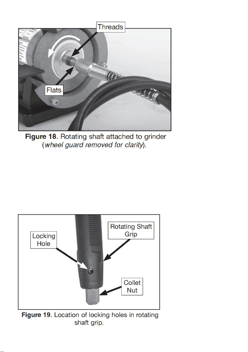
2. Thread rotating shaft onto spindle on right hand side of grinder (see Figure 18).
Tip: Hold wrench on flats of rotating shaft, then rotate grinding wheel
counterclockwise with free hand to tighten (see Figure 18).
38
Installing Bits
The Model uses bits and cutters with a 1 /8" diameter shaft.
To install a bit:
1. DISCONNECT MACHINE FROM POWER!
2. Rotate collet nut until locking holes in rotating shaft grip align (see Figure 19),
then insert pin wrench.
39
3. Loosen collet nut by turning counterclockwise.
Note: DO NOT completely remove collet nut from shaft.
4. Insert bit shank into collet.
Note: At least 1 /2" of bit shank should be mounted into end of collet.
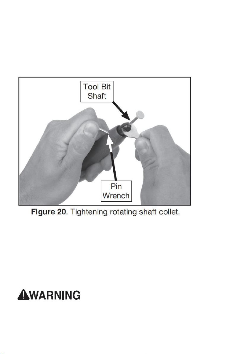
5. Hand-tighten collet nut while pin wrench is inserted into locking hole.
6. Tighten 1 /3 of a turn with collet wrench (see Figure 20). DO NOT over tighten.
Using Rotating Shaft
1. Install collet and bit.
2. Grasp tool firmly.
3. Turn tool ON.
4. Ease tool against workpiece using light pres sure.
Note: Always test bit on a scrap piece of material similar to workpiece.
Failure to wear safety glasses while operating grinder could cause serious
personal eye injury.

40
SECTION 6: MAINTENANCE
Schedule
For optimum performance from your machine, follow this maintenance schedule
and refer to any specific instructions given in this section.
Daily Check
• Loose mounting bolts.
• Cracked or loose grinding wheel.
• Damaged buffing wheel.
• Worn or damaged wires.
• Any other unsafe condition.
Cleaning & Protecting
Cleaning the machine is relatively easy. Vacuum excess debris, and wipe off the
remaining dust with a dry cloth.
Buffing Wheels
Keep buffing wheels raked out before each use and when buildup gets heavy
during use. Raking means to clean the buffing wheels with a wheel rake to
remove built-up compounds and metal particles. ALWAYS use light pressure
when raking wheels!

41
Grinding Wheels
The grinding wheel should be inspected before every use. Use the ring test
method noted in Wheel Inspection on Page 18 to verify the structural integrity.
Take care in storing grinding wheels to keep them free from potential damage
by being dropped or having other items drop on them.
Replace the wheel when the spark deflector or tool rest has no more adjustment
and the gap has exceeded the safe limit.
Wheel Dressing
Depending on the type of grinding you do, the grinding wheel may require periodic
dressing. Several different kinds of wheel dressing devices are available.
Dressing restores the abrasive quality of the wheel surface and squares up the
wheel edge. Refer to the instructions that accompany your dressing accessory for
complete details on how to properly dress a wheel.
Wheel Storage
Grinding wheels can be easily damaged, so it is important to store them properly.
Follow all wheel manufacturer storage instructions. Always store grinding wheels
in a location that is dry and protected from potential damage due to them being
dropped or having other items dropped on them. Also, avoid storing grinding
wheels where there is high humidity, extreme heat or cold, or solvents.
SECTION 7: SERVICE
Review the troubleshooting and procedures in this section if a problem develops
with your machine. If you need replacement parts or additional help with a
procedure, call our Technical Support. Note: Please gather the serial number and
manufacture date of your machine before calling.

42
Troubleshooting
Motor & Electrical
Symptom
Possible Cause
Possible Solution
Machine
does not
start or a
breaker
trips.
1. Switch disabling key removed.
2. Incorrect power supply voltage or
circuit size.
3. Blown fuse.
4. Power supply circuit breaker
tripped or fuse blown.
5. Motor wires connected incorrectly.
6. Motor at fault.
1. Install switch disabling key.
2. Ensure correct power supply voltage and
circuit size.
3. Replace fuse/ensure no shorts.
4. Ensure circuit is sized correctly and free of
shorts. Reset circuit breaker or replace fuse.
5. Correct motor wiring connections.
6. Test/repair/replace.
Machine
stalls or is
underpower
ed.
1. Machine undersized for task.
2. Motor wired incorrectly.
3. Motor overheated.
4. Run capacitor at fault.
5. Motor bearings at fault.
1. Use new grinding/buffing wheel; reduce the
feed rate.
2. Wire motor correctly.
3. Clean motor, let cool, and reduce workload.
4. Test/repair/replace.
5. Test/repair/replace.
Machine
has
vibration or
noisy
operation.
1. Machine incorrectly mounted to
workbench.
2. Motor or component loose.
3. Grinding wheel at fault/arbor hole
not round.
4. Motor bearings at fault.
5. Motor shaft bent.
1. Adjust feet, shim, or tighten mounting
hardware.
2. Inspect/replace damaged bolts/nuts, and
retighten with thread locking fluid.
3. Dress/replace grinding wheel.
4. Test by rotating shaft; rotational grinding/
loose shaft requires bearing replacement.
5. Test with dial indicator and replace motor.

43
Operation
Symptom
Possible Cause
Possible Solution
Machine slows
when operating.
1. Operator is using too much
pressure.
2. RPM too low.
1. Use less pressure when grinding.
2. Adjust RPM.
Wavy condition
on surface of
workpiece.
1. Machine vibrating.
2. Workpiece not being held
firmly.
3. Wheel face uneven.
4. Wheel is too hard.
1. Make sure machine is securely
mounted on a solid surface.
2. Use a holding device to firmly retain
workpiece.
3. Dress grinding wheel.
4. Use softer wheel, or reduce feed rate.
Lines on surface of
workpiece.
1. Impurity on wheel surface.
2. Workpiece not being held
tightly.
1. Dress grinding wheel.
2. Use a holding device to firmly retain
workpiece.
Burning spots
or cracks in the
workpiece.
1. Improper type of grinding
wheel.
2. Improper feed rate.
3. Workpiece requires quenching.
1. Try a wheel which is softer style or
coarser grit.
2. Slow down rate of movement of
workpiece into wheel.
3. Quench workpiece in water to cool.
Wheel dulls
quickly,
grit falls off.
1. Depth of cut too great.
2. Wheel is too soft.
3. Wheel diameter too small.
4. Bad wheel dress.
5. Defective wheel bonding.
1. Slow down rate of movement of
workpiece into wheel.
2. Wheel too soft for material being
ground; select harder bond.
3. Replace wheel.
4. Dress wheel.
5. Consult manufacturer of grinding wheel.

44
items
Description
1
Name
Bench Buffer Polisher
2
Model
TDS-75B
3
Param
eter
Voltage/Frequency:120VAC/60Hz,Horsepower:1/14HP,
Rated current:0.4A,Rated speed:3600rpm,Wheel size:
3"
4
Packa
ge
Size
290x200x185mm
5
G.W.
2.2KG
Manufacturer:Weihai Allwin Electrical & Mechanical Tech. Co., Ltd
Address:No.15-1 SICHAN ROAD, WENDENG,SHANDONG,CHINA


Technical Support and E-Warranty Certificate
www.vevor.com/support
