FD 9305 Page 1 of 2
Unterstell-Pufferspeicher 100 Liter für Wärmepumpen 353 360 / PSP 100 E
100 Litre Built-under Buffer Tank for Heat Pumps
Réservoir tampon sous-jacent 100 litres pour PAC
Montageanweisung / Installation Instructions / Notice de montage 452231.66.14
Aufstellung:
Die Aufstellung und Installation muss
von einer zugelassenen Fachfirma in
einem frostsicheren Raum mit kurzen
Leitungswegen erfolgen.
Die am Typenschild angegebenen
Betriebsüberdrücke dürfen nicht
überschritten werden.
Tauchheizkörper sind nur von
zugelassenen Elektroinstallateuren
nach dem entsprechenden Schaltbild
anzuschließen. Die Vorschriften des
EVU, VDE und DIN 4751-2 sind
zwingend zu beachten.
Der Pufferspeicher ist nur für die
Belastung durch eine dafür
vorgesehene, gleichmäßig
aufliegende Wärmepumpe konzipiert.
Andere, insbesondere punktuelle
Belastungen sind nicht zulässig.
Zum Einbau eines Tauchheizkörpers
ist die Kunststoffverkleidung an den
rückseitig vorgefertigten Stellen
auszuschneiden. Zu diesem Zweck
kann die Verkleidung durch leichtes
vorziehen unten in der Mitte entriegelt
und nach oben abgehoben werden.
Das Anschlusskabels kann in
Kunststoffverkleidung und Bodenteil
verlegt werden.
Installation:
Mounting and installation must be
performed by a qualified specialist
company. The unit must be installed in
a room protected from frost with short
pipe runs.
The maximum permissible operating
overpressure indicated on the type
plate must not be exceeded.
Immersion heaters may only be
connected by qualified electricians in
accordance with the corresponding
circuit diagram. The electrical
installation must be carried out in
accordance with all relevant
requirements of the energy supply
company, VDE and DIN 4751-2
regulations.
The buffer tank is only designed to
withstand strain by the intended,
evenly applied heat pump. Other
forms of strain, in particular when
limited to individual points, is not
permitted.
The appropriate parts on the rear of
the plastic covering need to be
removed in order to install the
immersion heater. The covering can
be removed by gently pulling the
bottom in the middle and then lifting
upwards.
The connection cable can be laid
through the plastic covering and the
bottom of the unit.
Mise en place
L’installation et l’intégration du
réservoir tampon doivent être
effectuées par une entreprise
spécialisée agréée !
Le réservoir doit être installé dans un
local à l’abri du gel et il faut éviter des
tuyauteries trop longues. Les pres-
sions de service indiquées sur la
plaque signalétique ne doivent pas
être dépassées. Seul un électricien
agréé est autorisé à raccorder des
thermoplongeurs suivant le schéma
électrique correspondant. Il faut
impérativement respecter les
prescriptions du distributeur d’énergie
ainsi que les prescriptions VDE et DIN
4751-2.
Le ballon tampon est conçu
uniquement pour la charge d'une
pompe à chaleur reposant dessus
uniformément et prévue à cet effet.
Les autres charges, en particulier les
charges ponctuelles, ne sont pas
autorisées.
Pour monter un thermoplongeur, il
faut découper l’habillage en plastique
aux emplacements préparés à cet
effet à l’arrière de l’appareil.
Déverrouiller l’habillage en le tirant en
bas et au milieu légèrement vers
l’avant. Le retirer par le haut.
Le câble de raccordement peut être
passé dans l’habillage en plastique et
le socle.

FD 9305 Page 2 of 2
Hinweise:
Der Pufferspeicher ist nicht emailliert
und darf deshalb auf keinen Fall für
die Brauchwasser-Erwärmung
verwendet werden.
Alle Anschlüsse sind aus der
Isolierung herausgeführt. Wird ein
Anschlußstutzen nicht belegt, so ist er
mit einer Kappe oder einem Stopfen
abzudichten.
Am unteren Stutzen sollte eine
Entleerungsmöglichkeit vorgesehen
werden.
Wenn der Pufferspeicher mit einem
Tauchheizkörper ausgerüstet ist,
muss er mit einem baumustergeprü-
ftem, nicht absperrbarem Membran-
Sicherheitsventil angeschlossen
werden. Der Anschlußdurchmesser
muss mindestens DN 20 betragen.
Die Ausblasleitung darf keine
Drucksteigerungen ermöglichen.
Inbetriebnahme:
Vor Inbetriebnahme prüfen, ob die
Wasserzufuhr geöffnet und der
Speicher gefüllt ist. Hierbei ist die
Funktion und die Dichtigkeit der
gesamten Anlage einschließlich der
im Herstellwerk montierten Teile zu
prüfen.
Die Funktionssicherheit des
Sicherheitsventils ist in regelmäßigen
Abständen zu überprüfen.
Note:
Buffer tanks are not enamelled and,
for this reason, should never be used
for heating water for domestic use.
All connections are led through the
insulation. If a connection is not used,
it should be sealed with a cap or plug.
A drain plug should be provided on
the lower stub.
If the buffer tank is fitted with an
immersion heater, it must be
connected using a type-tested
diaphragm safety valve which
cannot be shut off. The connection
diameter must have a nominal width
of at least 20. The air outlet pipe must
not allow any pressure increase to
take place.
Start-up:
Ensure that the water supply is turned
on and the tank is filled before start-up.
The entire system, including all
factory-assembled components,
should be inspected to ensure that
everything is working properly and
that there is no leakage.
The operational reliability of the safety
valve should be checked at regular
intervals.
Indications
Le réservoir tampon n’est pas émaillé
et ne doit donc en aucun cas être
utilisé pour le réchauffement d’eau
sanitaire.
Tous les raccordements sont sortis
hors de l’isolation. Si un raccord reste
inutilisé, il doit être bouché avec un
capuchon ou un bouchon.
Une possibilité de vidange doit être
prévue sur la tubulure du bas.
Au cas où le réservoir tampon est
équipé d’un thermoplongeur, il faut le
raccorder à une vanne de sûreté à
membrane homologuée, non-
verrouillable. Il faut prévoir un
diamètre nominal d’au moins DN 20
pour effectuer le branchement. La
conduite d’évacuation d’air ne doit en
aucun cas permettre une élévation de
la pression.
Mise en service
Avant la mise en service, vérifier si
l’alimentation en eau est assurée et si
le réservoir est rempli. Il faut contrôler
le bon fonctionnement et l’étanchéité
de toute l’installation, y compris les
pièces montées en usine.
Il faut contrôler à intervalles réguliers
la sécurité de fonctionnement de la
vanne de sûreté.
FD 9305 Page 3 of 2
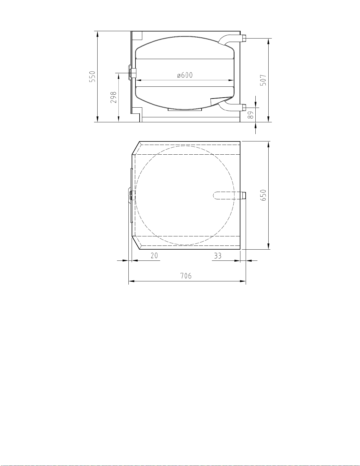
Nenninhalt
Höhe
Breite
Tiefe
Gewicht
Anschlüsse:
Heizstabeinsätze 1½“ IG
Heizwasservorlauf 1¼" AG
Heizwasserrücklauf 1¼" AG
zul. Betriebstemperatur
Heizwasser
zul. Betriebsüberdruck
Heizwasser
Nominal volume
Height
Width
Depth
Weight
Connections:
Imm. heat. inserts 1½“ int. thr.
Heat. water flow 1¼" ext. thr.
Heat. water ret. flow 1¼" ext. thr.
Max. permissible operating
temperature, heating water
Max. permissible operating
overpressure, heating water
Capacité nominale
Hauteur
Largeur
Profondeur
Poids
Raccords:
Inserts thermoplongeurs 1½“ fil.int.
Départ eau chauffage 1¼“ fil. ext.
Retour eau chauffage 1¼“ fil. ext.
Température de fonctionnement
autorisée eau de chauffage
Surpression de fonctionnement
autorisée eau de chauffage
l
mm
mm
mm
kg
Anz./no./n°
HV/HF/DE
HR/HR/RE
°C
bar
100
550
650
653
45
1
95
3
Anlage 1: Appendix 1: Annexe 1
Abmaße und technische Daten Dimensions and technical data Dimensions et données techniques