PSW 1000
PSW 1000 SOL
Montageanweisung
DeutschEnglishFrançaisPolski
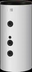
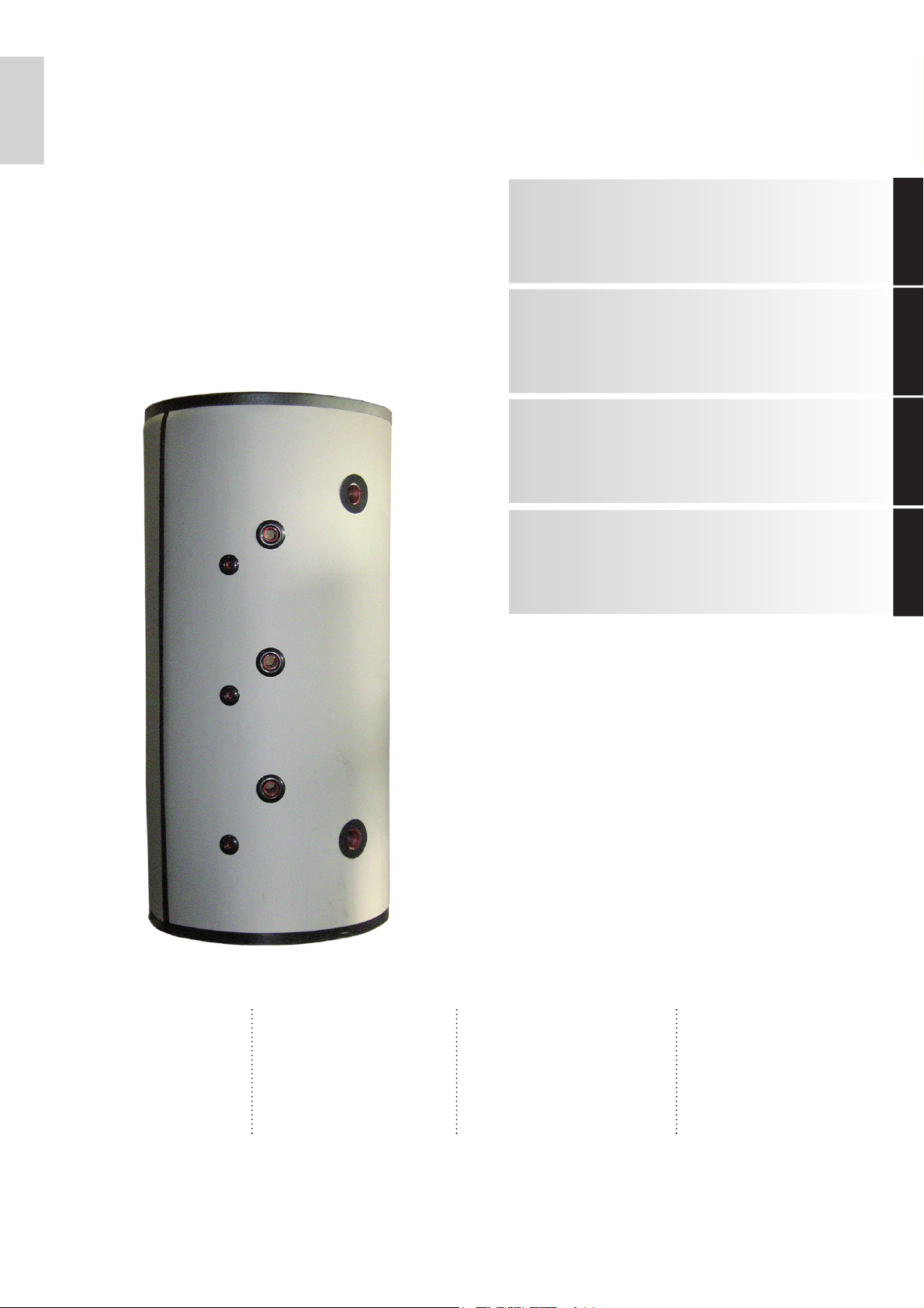
Pufferspeicher
1000 Liter für
Wärmepumpen
Buffer tank
(1000 litres) for
heat pumps
Ballon tampon
de 1000 litres
pour les pompes
à chaleur
Zasobnik
buforowy
1000 litrowy dla
pomp ciepła
Installation instructions
Instructions de montage
Instrukcja montażu
Bestell-Nr. / Order no. / No de commande / Nr zamówienia: GDD/PSW 1000 FD 9101


www.dimplex.de DE-1
Deutsch
Inhaltsverzeichnis
1 Aufstellung.................................................................................................................................. DE-2
1.1 Sicherheitsventil:.................................................................................................................................. DE-2
1.2 Inbetriebnahme:................................................................................................................................... DE-2
2 Technische Daten....................................................................................................................... DE-3
2.1 Abmessungen Pufferspeicher PSW 1000 ...........................................................................................DE-3
2.2 Abmessungen Pufferspeicher PSW 1000 SOL ................................................................................... DE-4
2.3 Technische Daten Pufferspeicher........................................................................................................ DE-5
DE-2
Deutsch
1
1 Aufstellung
Die Montage und Installation des Speichers muss durch eine zu-
gelassene Fachfirma erfolgen!
Der Pufferspeicher muss an einem frostsicheren Ort aufgestellt
werden, die Leitungswege zum Wärmeerzeuger sind so kurz wie
möglich zu halten.
Die am Typenschild angegebenen Betriebsüberdrücke dürfen
nicht überschritten werden. Elektroheizstäbe (Tauchheizkörper)
dürfen nur von autorisierten Elektrofachkräften nach entspre-
chendem Schaltbild angeschlossen werden. Die Vorschriften
des EVU, VDE und DIN 4751-2 sind zwingend einzuhalten.
HINWEIS!
Die Pufferspeicher sind nicht emailliert und dürfen auf keinen Fall für die
Brauchwasser-Erwärmung verwendet werden.
HINWEIS!
Alle Anschlüsse sind aus dem Speicher herausgeführt und bündig mit
der Isolierung. Wird ein Anschlussstutzen nicht belegt ist er mit einem
Stopfen oder einer Kappe abzudichten.
HINWEIS!
Die Speicherwärmedämmung ist in den kalten Monaten vor der Montage
bei Zimmertemperatur zu lagern um Schäden an der Dämmung und am
Verschlussmechanismus zu vermeiden!
HINWEIS!
Am unteren Stutzen (Speicherboden) sollte eine Entleerungsvorrichtung
vorgesehen werden.
1.1 Sicherheitsventil:
Wird der Pufferspeicher mit einem oder mehreren Tauchheizkör-
pern ausgerüstet muss dieser zusätzlich mit einem baumuster-
geprüften, nicht absperrbaren Membran-Sicherheitsventil ausge-
stattet werden.
Der Anschlussdurchmesser muss mindestens Nennweite (NW)
20 betragen. Die Ausblasleitung darf keine Drucksteigerungen
ermöglichen.
Die Funktionssicherheit des Sicherheitsventils ist in regelmäßi-
gen Abständen zu überprüfen.
1.2 Inbetriebnahme:
Vor Inbetriebnahme prüfen, ob die Wasserzufuhr geöffnet und
der Speicher gefüllt ist.
Erstbefüllung und Inbetriebnahme müssen von einem zugelas-
senen Fachbetrieb durchgeführt werden.
Bei der Inbetriebnahme sind die Funktion und Dichtheit der ge-
samten Anlage einschließlich der montierten Teile zu prüfen.
Der Elektroheizstab (falls vorhanden) ist jährlich, bei entspre-
chend hartem Wasser auch in kürzeren Abständen zu entkalken
und mit einer Funktionskontrolle zu verbinden.
HINWEIS!
Die Dämmung des Pufferspeichers ist im Auslieferungszustand nur für
Heizzwecke geeignet.
Soll der Speicher für Kühlzwecke eingesetzt werden ist der Speicher
bauseits mit einer dampfdiffusionsdichten Dämmung zu versehen.
Einzubeziehen sind alle Heizungsanschlüsse, inkl. der Muffen für die
Tauchheizkörper um Kondensatbildung im Kühlbetrieb am
Pufferspeicher zu vermeiden.
www.dimplex.de DE-3
Deutsch
2.1
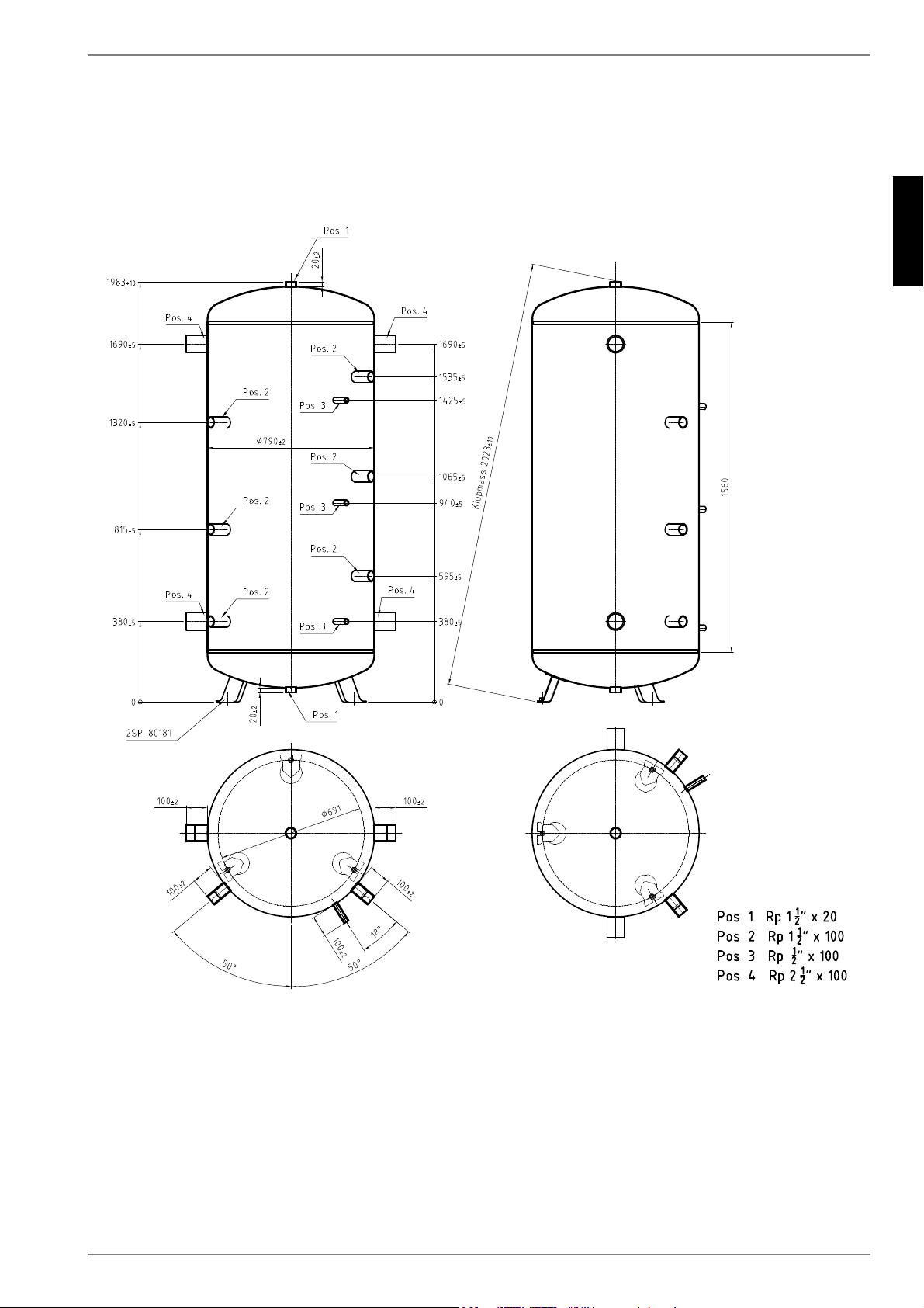
2 Technische Daten
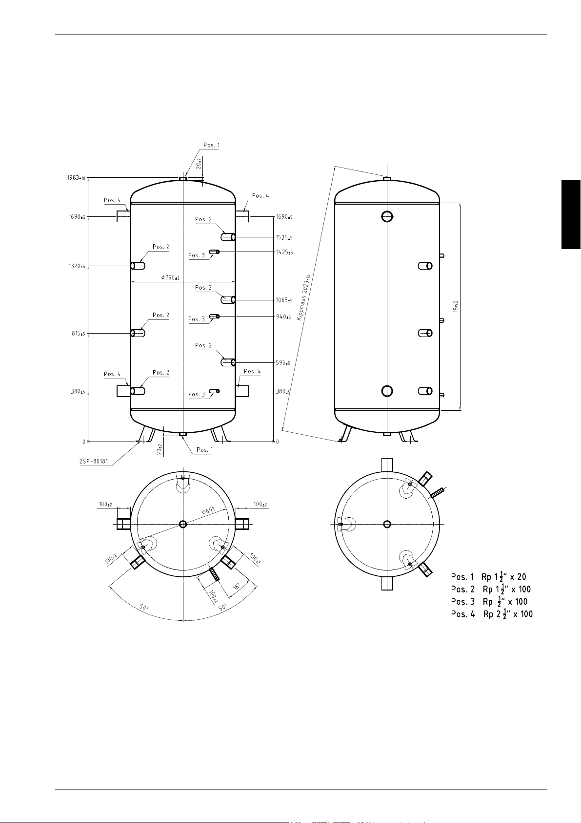
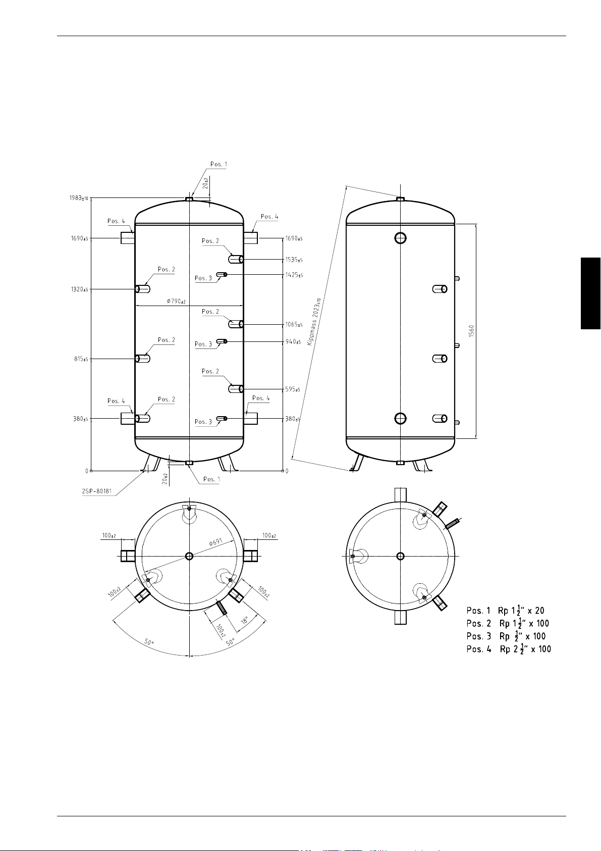
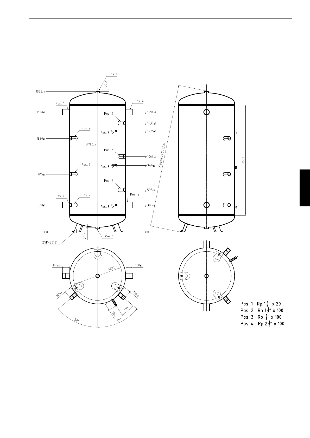
2.1 Abmessungen Pufferspeicher PSW 1000
DE-4
Deutsch
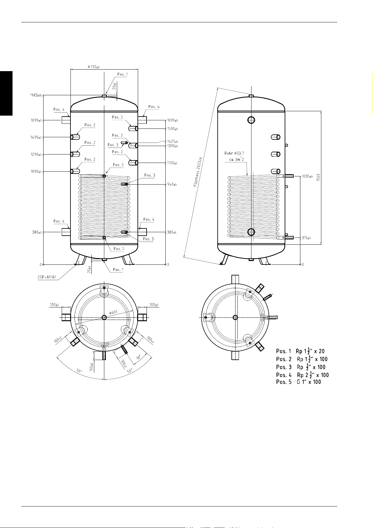
2.2
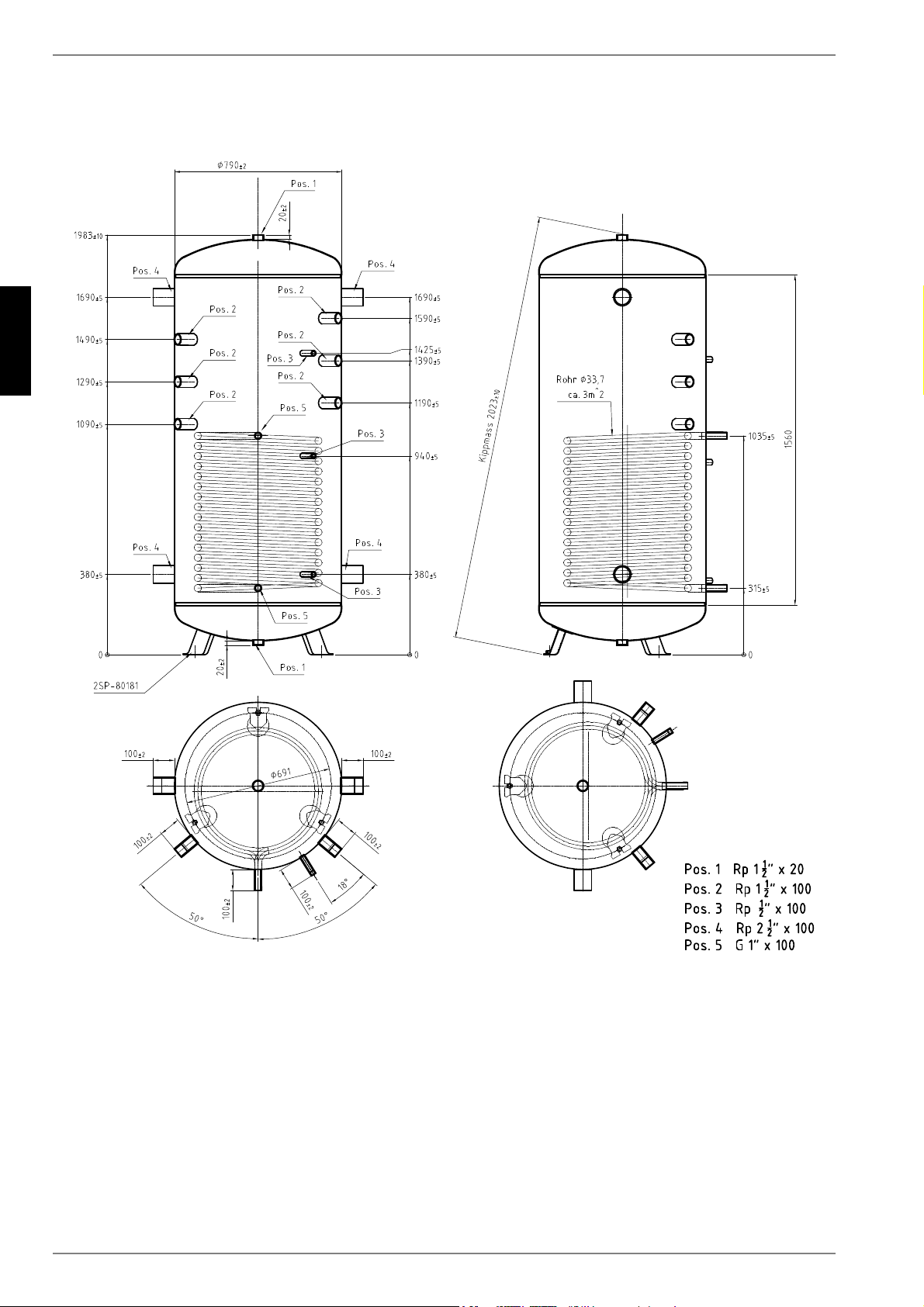
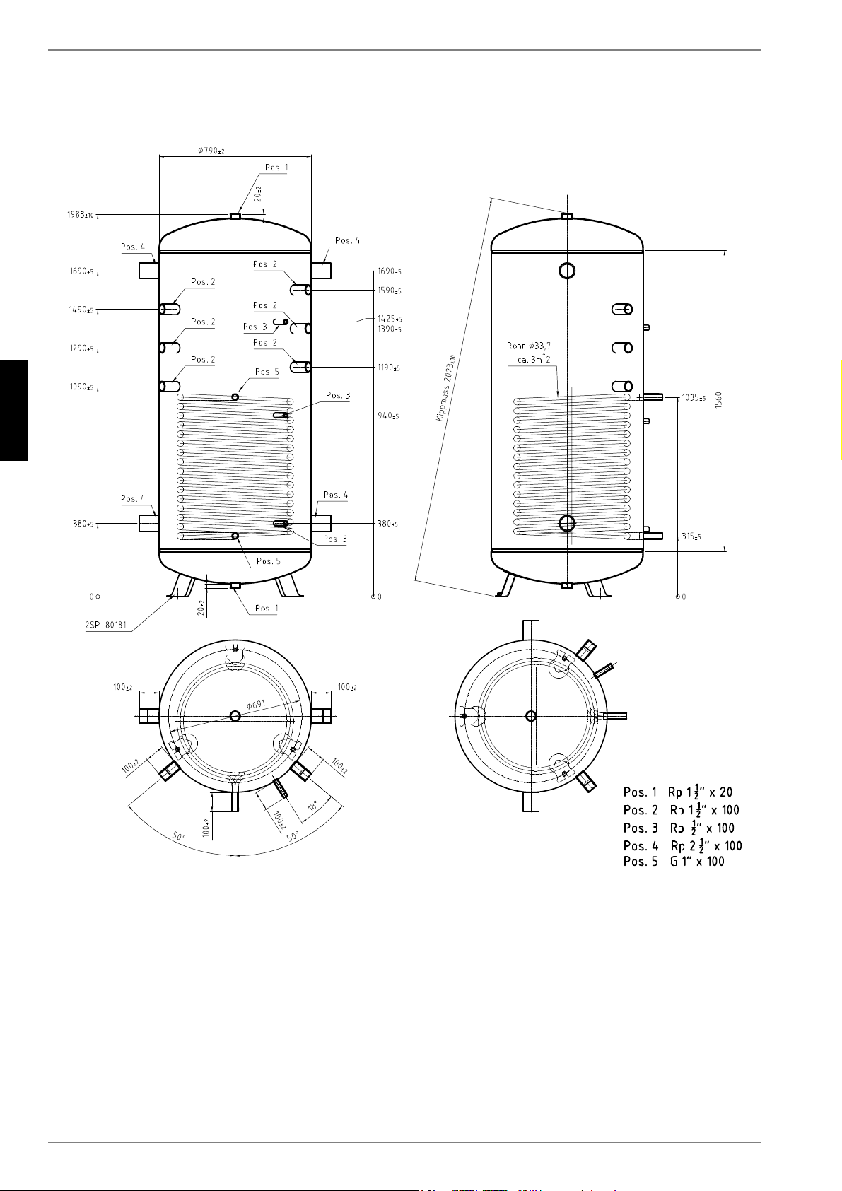
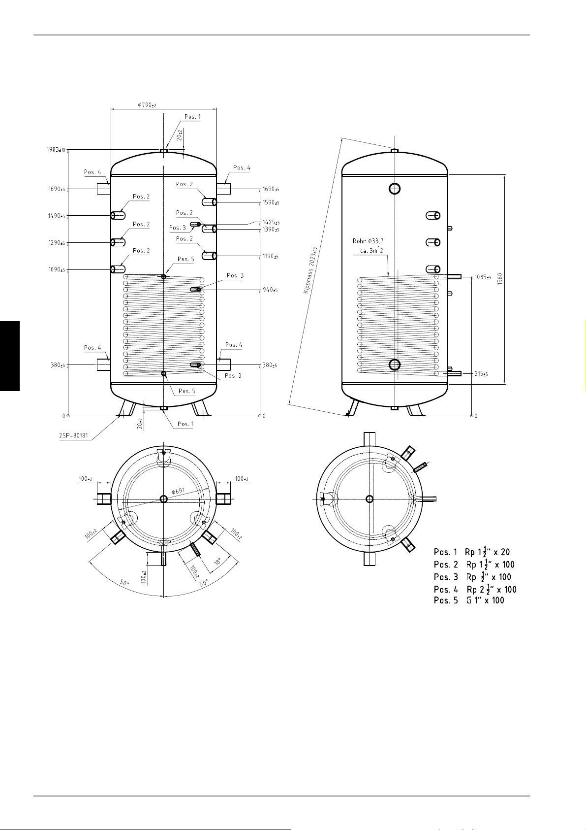
2.2 Abmessungen Pufferspeicher PSW 1000 SOL
www.dimplex.de DE-5
Deutsch
2.3
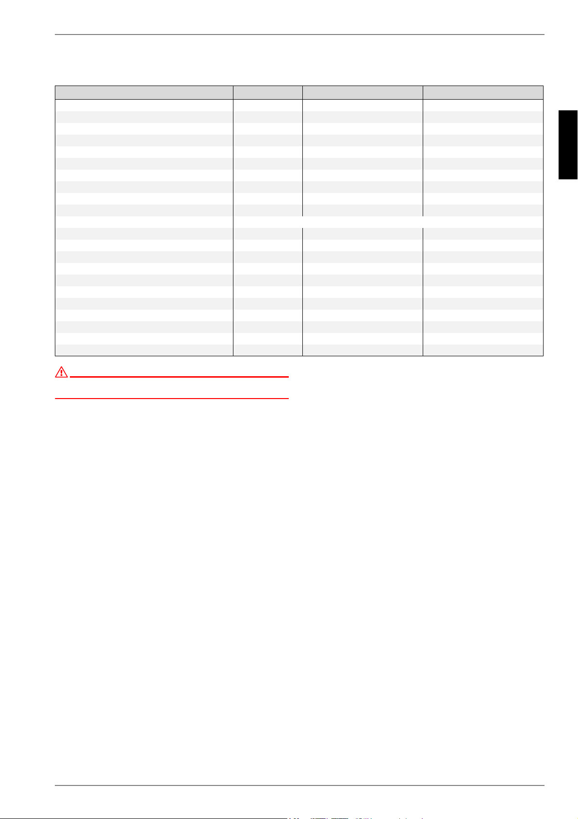
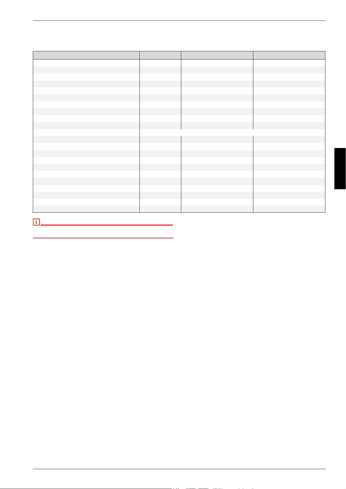
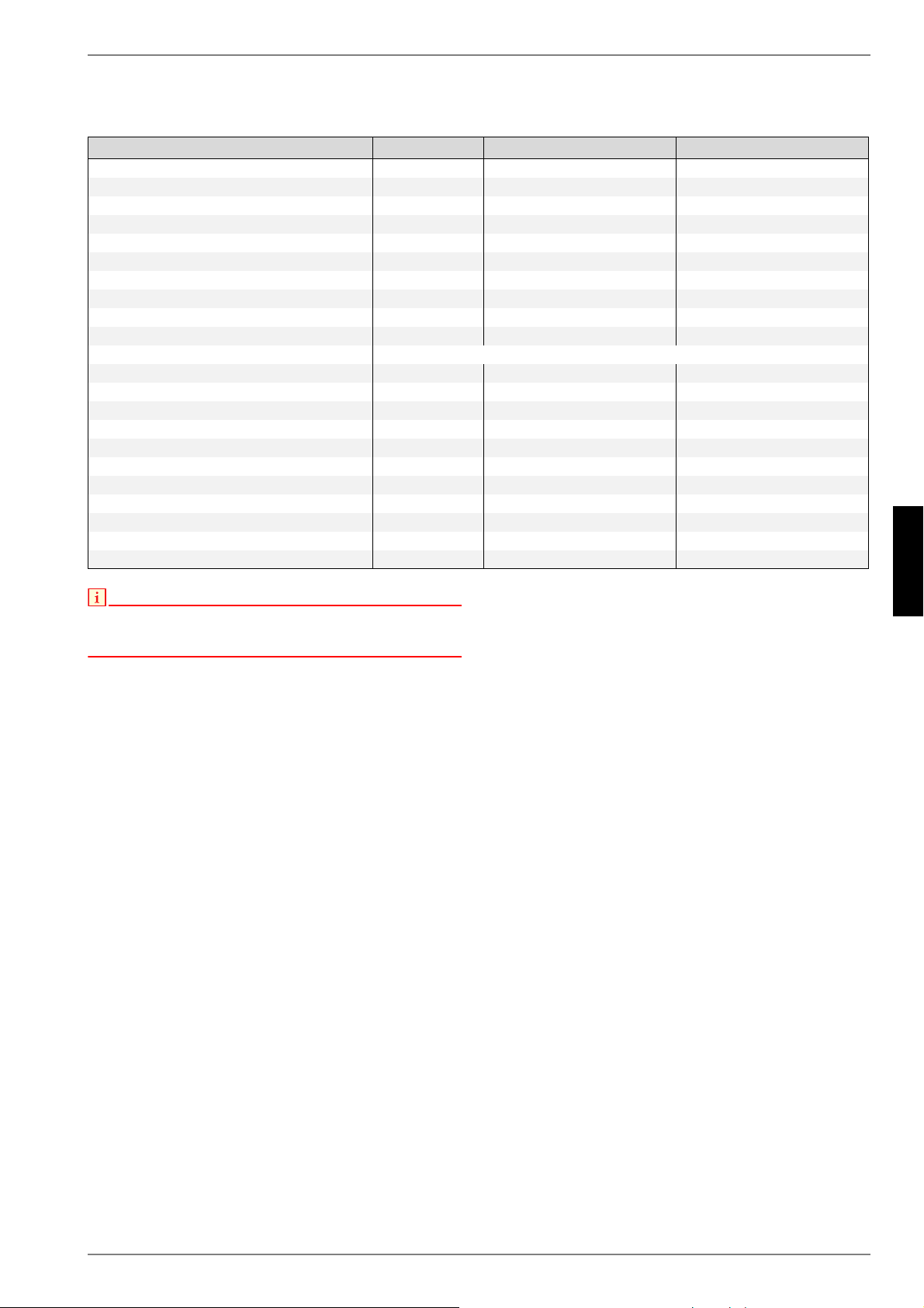
2.3 Technische Daten Pufferspeicher
HINWEIS!
Beigefügtes Typschild und Anschlussplan nach Aufstellung und
Montage der Dämmung sichtbar auf den Speichermantel aufkleben.
Technische Angaben in PSW 1000 PSW 1000 SOL
Nenninhalt
Liter 1000 1000
Solar-Wärmetauscherfläche
m² -- 3
Nutzinhalt
Liter 980 950
Kippmass
mm 2023 2023
Höhe
mm 1983 1983
Durchmesser ohne Isolierung
mm 790 790
Durchmesser mit Isolierung
mm 980 890
Dämmstärke Isolierung
mm 90 90
Gewicht ohne Isolierung
kg 93 123
Gewicht Isolierung
kg 13 13
Anschlüsse
Heizstabeinsätze 1 1/2“ IG
Anzahl 6 6
Anschluss für Entlüftung
Zoll 1 1/2“ IG (Blindstopfen) 1 1/2“ IG (Blindstopfen)
Anschluss für Entleerung
Zoll 1 1/2“ IG (Blindstopfen) 1 1/2“ IG (Blindstopfen)
Heizwasservorlauf
Zoll 2 1/2“ IG 2 1/2“ IG
Heizwasserrücklauf
Zoll 2 1/2“ IG 2 1/2“ IG
Solaranschluss Vorlauf
Zoll 1“ AG
Solaranschluss Rücklauf
Zoll 1“ AG
Tauchhülsen Rp 1/2“, Länge 150mm
Anzahl 3 3
Stellfüße
Anzahl 3 3
zul. Betriebstemperatur Heizwasser
°C 95 95
zul. Betriebsdruck Heizwasser
bar 3 3

DE-6
Deutsch
2.3

www.dimplex.de GB-1
English
Table of contents
1 Installation ..................................................................................................................................GB-2
1.1 Safety valve ......................................................................................................................................... GB-2
1.2 Start-up ................................................................................................................................................ GB-2
2 Technical data ............................................................................................................................GB-3
2.1 Buffer tank dimensions PSW 1000 ...................................................................................................... GB-3
2.2 Buffer tank dimensions PSW 1000 SOL.............................................................................................. GB-4
2.3 Technical Data Buffer tank .................................................................................................................. GB-5
GB-2
English
1
1 Installation
The buffer tank must be mounted and installed by an authorised
specialist company!
The buffer tank must be installed in a frost-free location. The pipe
runs to the heat generator must be kept as short as possible.
The operating overpressures indicated on the type plate must not
be exceeded. Electric heating elements (immersion heaters)
must only be connected by authorised electricians according to
the corresponding circuit diagram. All relevant requirements of
the utility company, the Association of German Engineers (VDE)
and DIN 4751-2 must be observed.
NOTE
The buffer tanks are not enamelled and, for this reason, must never be
used for heating water for domestic use.
NOTE
All connections lead out from the buffer tank and are flush to the
insulation. If a connecting stub is not in use, it should be sealed using a
cap or sealing plug.
NOTE
During the cold months, the thermal insulation of the buffer tank must be
stored at room temperature before installation in order to avoid damage
to the insulation and fastening mechanism.
NOTE
A means of draining the tank should be provided on the lower stub (base
of the buffer tank).
1.1 Safety valve
If the buffer tank is fitted with one or more immersion heaters, it
must additionally be equipped with a type-tested diaphragm
safety valve which cannot be shut off.
The connection diameter must have a nominal width (NW) of at
least 20. The air outlet pipe must not allow any pressure increase
to take place.
The operational reliability of the safety valve must be checked at
regular intervals.
1.2 Start-up
Ensure that the water supply is turned on and the buffer tank is
filled before start-up.
The initial filling and start-up must be carried out by an authorised
specialist company.
The entire system, including all assembled components, must be
inspected to ensure that everything is working properly and that
there is no leakage.
The electric heating element (if present) should be de-scaled and
tested anually (or more frequently in hard water areas).
NOTE
The thermal insulation supplied with the buffer tank is only suitable for
heating purposes.
If the tank is to be used for cooling purposes, it must be fitted with steam-
resistant insulation (to be provided by the customer). This must include
all heating connections (also including the sleeves for the immersion
heaters) in order to prevent condensate from forming on the buffer tank
during cooling operation.
www.dimplex.de GB-3
English
2.1
2 Technical data
2.1 Buffer tank dimensions PSW 1000
GB-4
English
2.2
2.2 Buffer tank dimensions PSW 1000 SOL

GB-6
English
2.3

www.dimplex.de FR-1
Français
Table des matières
1 Installation .................................................................................................................................. FR-2
1.1 Vanne de sécurité.................................................................................................................................FR-2
1.2 Mise en service.....................................................................................................................................FR-2
2 Caractéristiques techniques ..................................................................................................... FR-3
2.1 Dimensions du ballon tampon PSW 1000 ............................................................................................FR-3
2.2 Dimensions du ballon tampon PSW 1000 SOL....................................................................................FR-4
2.3 Données techniques du ballon tampon ................................................................................................FR-5
FR-2
Français
1
1 Installation
Le montage et l'installation du ballon doivent être effectués par
une entreprise spécialisée agréée !
Le ballon tampon doit être installé dans un endroit protégé du gel
; les conduites vers le générateur de chaleur doivent être tenues
aussi courtes que possible.
Les surpressions de service indiquées sur la plaque signalétique
ne doivent pas être dépassées. Seul un spécialiste électricien
compétent est habilité à raccorder les cartouches électriques
chauffantes (résistances immergées) selon le schéma de
câblage correspondant. Les prescriptions de la société
d'électricité ainsi que les prescriptions VDE et DIN 4751-2
doivent être impérativement respectées.
REMARQUE
Les ballons tampon ne sont pas émaillés et ne doivent en aucun cas être
utilisés pour le réchauffement d’eau sanitaire.
REMARQUE
Tous les raccordements sont sortis du ballon et affleurent par rapport à
l'isolation. Si une tubulure de raccordement n’est pas utilisée, elle doit
être bouchée avec un capuchon ou un bouchon.
REMARQUE
L'isolation thermique du ballon doit être conservée à température
ambiante durant les mois d'hiver avant l'installation afin d'éviter tout
dommage sur l'isolation et sur le mécanisme de verrouillage !
REMARQUE
Prévoir une possibilité de vidange sur la tubulure du bas (base du ballon).
1.1 Vanne de sécurité
Si le ballon tampon est équipé d’une ou plusieurs résistances im-
mergées, celle(s)-ci doi(ven)t être pourvue(s) en plus d'une
vanne de sécurité à membrane homologuée, ne pouvant être
bloquée.
Prévoir un diamètre nominal d’au moins DN 20 pour le
raccordement. La conduite d’évacuation d’air ne doit en aucun
cas rendre possible une élévation de la pression.
Contrôler à intervalles réguliers le bon fonctionnement de la
vanne de sécurité.
1.2 Mise en service
Avant la mise en service, vérifier si l’alimentation en eau est as-
surée et le ballon d’eau chaude sanitaire rempli.
Le premier remplissage et la première mise en service doivent
être effectuées par une entreprise autorisée.
Lors de la mise en service, contrôler le bon fonctionnement et
l’étanchéité de l'ensemble de l’installation, y compris les pièces
pré-montées.
La cartouche électrique chauffante (si existante) doit être
détartrée une fois par an, et, pour une qualité de l’eau
relativement dure à des intervalles plus courts. Un contrôle des
fonctions doit être également effectué.
REMARQUE
À la livraison, l'isolation du ballon tampon est uniquement conçue à des
fins de chauffage.
Si le ballon doit être utilisé à des fins de rafraîchissement, il doit être
équipé d'une isolation étanche à la diffusion, à procurer par le client.
Tous les raccords de chauffage doivent être intégrés (y compris les
manchons de la résistance immergée) pour éviter la formation de
condensat en mode rafraîchissement sur le ballon tampon.
www.dimplex.de FR-3
Français
2.1
2 Caractéristiques
techniques
2.1 Dimensions du ballon tampon PSW 1000
FR-4
Français
2.2
2.2 Dimensions du ballon tampon PSW 1000 SOL
www.dimplex.de FR-5
Français
2.3
2.3 Données techniques du ballon tampon
REMARQUE
Apposer la plaque signalétique jointe et le schéma électrique de manière
visible sur l'enveloppe du ballon une fois l'isolation montée et installée.
Données techniques en PSW 1000 PSW 1000 SOL
Capacité nominale
litres 1000 1000
Surface d'échange thermique solaire
m² -- 3
Capacité utile
litres 980 950
Hauteur (appareil basculé)
mm 2023 2023
Hauteur
mm 1983 1983
Diamètre sans isolation
mm 790 790
Diamètre avec isolation
mm 980 890
Épaisseur d'isolant
mm 90 90
Poids sans isolation
kg 93 123
Poids isolation
kg 13 13
Raccords
Raccords cartouche chauffante filet. int. 1 ½“
Nombre 6 6
Raccordement de la purge
Pouce(s) filet. int. 1 ½“ (bouchons borgnes) filet. int. 1 ½“ (bouchons borgnes)
Raccordement de la vidange
Pouce(s) filet. int. 1 ½“ (bouchons borgnes) filet. int. 1 ½“ (bouchons borgnes)
Circuit de départ d’eau de chauffage
Pouce(s) filet. int. 2 ½“ filet. int. 2 ½“
Circuit de retour d’eau de chauffage
Pouce(s) filet. int. 2 ½“ filet. int. 2 ½“
Circuit de départ raccordement solaire
Pouce(s) filet. ext. 1“
Circuit de retour raccordement solaire
Pouce(s) filet. ext. 1“
Doigts de gant Rp 1/2“, Longueur 150mm
Nombre 3 3
Pieds réglables
Nombre 3 3
Température de service admissible eau de chauffage
°C 95 95
Pression de service admissible eau de chauffage
bars 3 3

FR-6
Français
2.3

www.dimplex.de PL-1
Polski
Spis tresci
1 Ustawienie................................................................................................................................... PL-2
1.1 Zawór bezpieczeństwa .........................................................................................................................PL-2
1.2 Pierwsze uruchomienie.........................................................................................................................PL-2
2 Dane techniczne ......................................................................................................................... PL-3
2.1 Wymiary zasobnika buforowego PSW 1000.........................................................................................PL-3
2.2 Wymiary zasobnika buforowego PSW 1000 SOL ................................................................................PL-4
2.3 Dane techniczne zasobnika buforowego.............................................................................................. PL-5
PL-2
Polski
1 Ustawienie
Montaż i instalację zasobnika musi przeprowadzić
specjalistyczna firma!
Zasobnik buforowy należy ustawić w zabezpieczonym przed
mrozem miejscu, rurociągi prowadzące do generatora ciepła
powinny być jak najkrótsze.
Nie wolno przekroczyć podanego na tabliczce znamionowej
nadciśnienia roboczego. Elektryczne grzałki (grzałka nurkowa)
mogą być podłączane tylko przez autoryzowanych fachowców
elektryków według odpowiedniego schematu. Należy koniecznie
przestrzegać przepisów EVU, VDE i DIN 4751-2.
WSKAZÓWKA
Zasobniki buforowe nie są emaliowane i dlatego nie mogą
w żadnym wypadku być używane do podgrzewania wody użytkowej.
WSKAZÓWKA
Wszystkie podłączenia są wyprowadzone z zasobnika
i zaizolowane. Jeżeli jeden z króćców przyłączeniowych nie jest używany,
to należy go uszczelnić pokrywą lub zatyczką.
WSKAZÓWKA
Izolację cieplną zasobnika należy podczas zimnych miesięcy przed
montażem przechowywać w temperaturze pokojowej, aby zapobiec
uszkodzeniom izolacji
i mechanizmu zamykania!
WSKAZÓWKA
Należy zaplanować urządzenie opróżniające na dolnym króćcu (spód
zasobnika).
1.1 Zawór bezpieczeństwa
Jeżeli zasobnik buforowy jest wyposażony w jedną lub więcej
grzałek nurkowych, to musi posiadać dodatkowo sprawdzony
pod względem typu konstrukcyjnego, niezamykający się
membranowy zawór bezpieczeństwa.
Średnica podłączenia musi mieć co najmniej wielkość
znamionową (NW) 20. Przewód wydmuchowy nie może
powodować żadnego wzrostu ciśnienia.
Należy regularnie sprawdzać prawidłowe funkcjonowanie
zaworów bezpieczeństwa.
1.2 Pierwsze uruchomienie
Przed pierwszym uruchomieniem sprawdzić, czy jest otwarty
dopływ wody i czy zasobnik jest pełny.
Pierwsze napełnienie i uruchomienie musi przeprowadzić firma
specjalistyczna z uprawnieniami.
Podczas pierwszego uruchomienia należy sprawdzić
funkcjonowanie i szczelność całej instalacji łącznie
z montowanymi częściami.
Grzałkę elektryczną (jeżeli jest) należy raz w roku, przy twardej
wodzie częściej, oczyścić z osadu wapiennego i sprawdzić jej
funkcjonowanie.
WSKAZÓWKA
Dostarczona fabrycznie izolacja zasobnika buforowego nadaje się tylko
do celów grzewczych.
Jeżeli zbiornik ma być wykorzystany w celach chłodzenia musi zostać
wyposażony przez użytkownika w izolację zapobiegającą dyfuzji pary
wodnej.
Należy w to włączyć wszystkie przyłącza ogrzewania łącznie z mufami dla
grzałki zanurzeniowej aby uniknąć tworzenia się kondensatu na zbiorniku
buforowym w trybie chłodzenia.
www.dimplex.de PL-3
Polski
2 Dane techniczne
2.1 Wymiary zasobnika buforowego PSW 1000
PL-4
Polski
2.2 Wymiary zasobnika buforowego PSW 1000 SOL
www.dimplex.de PL-5
Polski
2.3 Dane techniczne zasobnika buforowego
WSKAZÓWKA
Po ustawieniu i montażu izolacji należy przykleić
w widocznym miejscu na obudowie zasobnika załączoną tabliczkę
znamionową i plan podłączeń.
Dane techniczne w PSW 1000 PSW 1000 SOL
pojemność znamionowa
litr 1000 1000
powierzchnia słonecznego wymiennika ciepła
m -- 3
pojemność użytkowa
litr 980 950
w przechyle
mm 2023 2023
wysokość
mm 1983 1983
średnica bez izolacji
mm 790 790
średnica z izolacją
mm 980 890
grubość izolacji izolacja
mm 90 90
ciężar bez izolacji
kg 93 123
ciężar izolacji
kg 13 13
przyłącza
wkłady grzałki 1 1/2“ gwint wew.
Ilość 6 6
podłączenie dla odpowietrzania
cal 1 1/2“ gwint wew. (zaślepka) 1 1/2“ gwint wew. (zaślepka)
podłączenie dla opróżniania
cal 1 1/2“ gwint wew. (zaślepka) 1 1/2“ gwint wew. (zaślepka)
zasilanie wody grzewczej
cal 2 1/2“ gwint wew. 2 1/2“ gwint wew.
powrót wody grzewczej
cal 2 1/2“ gwint wew. 2 1/2“ gwint wew.
podłączenie zasilania słonecznego
cal 1“ gwint zew.
podłączenie powrotu ogrzewania słonecznego
cal 1“ gwint zew.
tuleje zanurzeniowe Rp 1/2“, Długość 150mm
Ilość 33
nóżki
Ilość 3 3
dopuszczalna temperatura robocza wody grzewczej
°C 95 95
dopuszczalne ciśnienie robocze wody grzewczej
bar 3 3

PL-6
Polski

www.dimplex.de PL-7
Polski

GDD GmbH
D-95326 Kulmbach
Irrtümer und Änderungen vorbehalten.
Subject to alterations and errors.
Sous réserve d’erreurs et modifications.
Zastrzegamy sobie prawo do zmian oraz bledów.