INSTALLATION INSTRUCTIONS
FOR RESIDENTIAL HYDRONIC BUFFER TANK
FOR MODELS: RBT 030, 050, 080 & 119
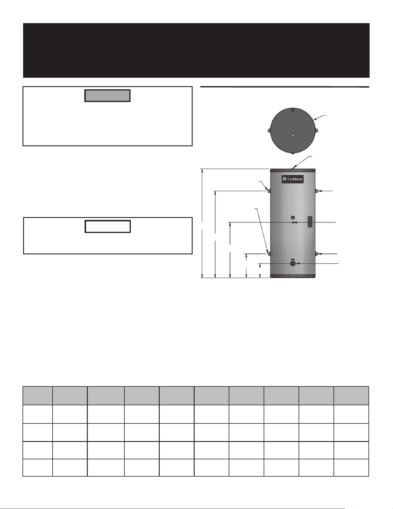
Dimensions and Specifications
Model
Number
Gallon
Capacity
A B
C D E F
Supply/
Return
Boiler
Tappings
RBT 30 30 4" 9 1/2"
17 1/8" 24 1/4" 34 1/4" 20 1/2" 1 1/2" 1 1/2"
RBT 50 50
3 3/4" 9 1/2"
25 3/4" 41 5/8" 53 7/8" 20 1/2" 1 1/2" 1 1/2"
RBT 80 80
3 3/4" 11 3/4"
29" 46 1/4" 58 3/8" 24" 2" 2"
RBT 119 119 3 3/4" 11 3/4" 30 1/8" 48 1/2" 61 5/8" 29 1/2" 2" 2"
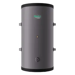
Figure 1 Buffer tank dimensions, refer to table below
• Hydronic buffer tanks are built with four (4) connections. Two
(2) connections can be piped to the heating appliance and two
(2) can be piped to the distribution system. If piped correctly
the buffer can serve as a hydraulic separator as well as a thermal
buffer. The heating appliance is therefore de-coupled from the
distribution system. Reference the piping diagrams on pages 2
and 3 of this instruction sheet.
• The buffer tank is also supplied with a 3/4" NPT vent connection,
3/4" drain opening, and a 3/8" sensor bulbwell. This bulbwell
is designed to accommodate sensors supplied with the boilers
or a Honeywell Aquastat control (TST20016) which can be
ordered from your Lochinvar distributor.
3/4" NPT VENT
CONNECTION
TO BUILDING
LOOP
FROM BUILDING
LOOP
FROM BOILER
BULBWELL
TO BOILER
3/4" NPT DRAIN
"F"
"E"
"D"
"C"
"B"
"A"
Application
The primary application of a buffer tank is to reduce boiler or
heat pump cycling. Hydronic buffer tanks are designed to be used
in systems operating below the designed load conditions, or in
systems having several low BTU heating loads calling at different
times.
Short cycling can result in reduced operating efficiency which
shortens the life of the appliance.
NOTICE
Use this vessel only in hydronic heating systems. DO NOT use
in potable water systems. The installer must comply with all
plumbing codes. DO NOT operate above the temperature or
pressure specified on the rating plate. Failure to comply may
result in personal injury, property damage, or death.
m WARNING
PRINTED 0715 332254-000
INDIRECT
DHW TANK
BACKFLOW
PREVENTER
PRESSURE
REDUCING VALVE
PRESSURE
GAUGE
ANTI-SCALD
MIXING VALVE
AIR SEPARATOR
EXPANSION
TANK
BALL VALVE
(TYPICAL)
MAKE UP WATER
FLOW CHECK
VALVE
(TYPICAL)
BOILER
CIRCULATOR
(TYPICAL)
BOILER 2
(MEMBER 1)
DOMESTIC
HOT WATER
CIRCULATOR
UNION
(TYPICAL)
HOT
WATER
OUT
COLD
WATER
IN
BOILER 1
(LEADER)
SYSTEM SUPPLY
SENSOR
(WHEN USED)
TEMPERATURE /
PRESSURE
GAUGE
DRAIN
(TYPICAL)
Y-STRAINER
(RECOMMENDED)
(TYPICAL)
BUFFER
TANK
AIR VENT
DRAIN
RECIRCULATION
PUMP
CHECK VALVE
RELIEF VALVE
IMG00564
ZONE #1 ZONE #2 ZONE #3 ZONE #4
2 of 4
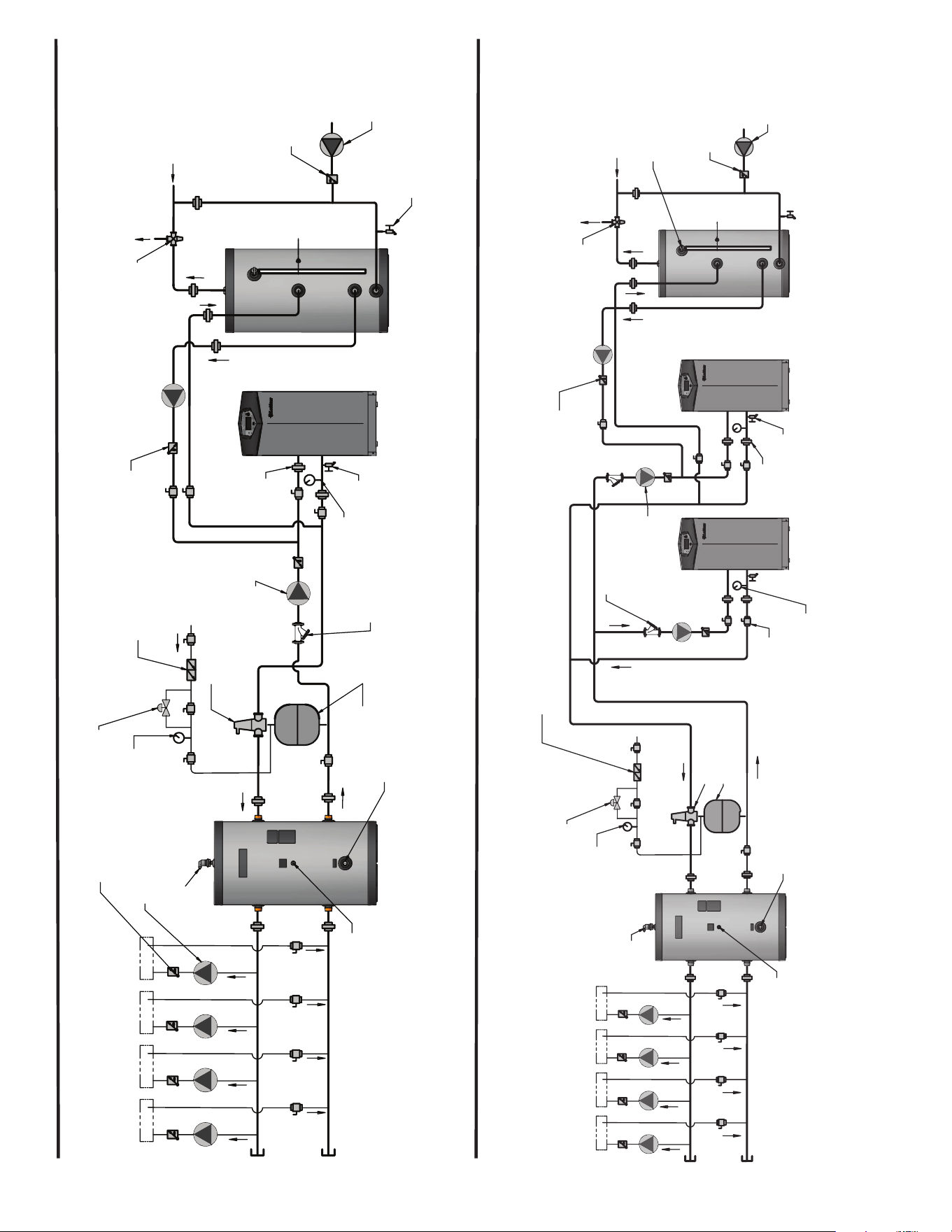
Figure 2 Single heater with zoned with circulators
BOILER
INDIRECT
DHW TANK
DOMESTIC
HOT WATER
CIRCULATOR
BACKFLOW
PREVENTER
PRESSURE
REDUCING VALVE
PRESSURE
GAUGE
ANTI-SCALD
MIXING VALVE
COLD
WATER
IN
TEMPERATURE /
PRESSURE
GAUGE
AIR SEPARATOR
EXPANSION
TANK
UNION
(TYPICAL)
DRAIN
FLOW CHECK
VALVE
MAKE UP WATER
HOT
WATER
OUT
ZONE CIRCULATORS
(TYPICAL)
FLOW CHECK
VALVE
(TYPICAL)
BOILER
CIRCULATOR
SYSTEM SUPPLY
SENSOR
(WHEN USED)
Y-STRAINER
(RECOMMENDED)
BUFFER
TANK
AIR VENT
RECIRCULATION
PUMP
CHECK VALVE
CHECK VALVE
DRAIN
IMG00563
ZONE #1 ZONE #2 ZONE #3 ZONE #4
Figure 3 Multiple heaters zoned with circulators

3 of 4
Figure 4 Geothermal heat pump
AIR SEPARATOR
MAKE UP WATER
BUFFER
TANK
AIR VENT
DRAIN
FROM EARTH
TO EARTH
GEO-THERMAL
UNIT
FLOW CHECK
VALVE
(TYPICAL)
ZONE CIRCULATORS
(TYPICAL)
SYSTEM SUPPLY
SENSOR (WHEN USED)
PRESSURE REDUCING
VALVE
PRESSURE
GAUGE
BACKFLOW
PREVENTER
UNION
(TYPICAL)
HEAT SOURCE
CIRCULATOR
EXPANSION
TANK
ZONE #1 ZONE #4ZONE #3
ZONE #2
Please note that these illustrations are meant to show system piping concept only, the installer is responsible for all
equipment and detailing required by local codes.
NOTICE

4 of 4