Loading ...
Loading ...
Loading ...
15
En
Creating sounds and categories/parameters
! Vibrato: Periodic change in sound pitch
! Wah Wah: Periodic change in tone
! Tremolo: Periodic change in volume
LFO parameters
The following parameters appear under the [LFO] category in the display
except for “Parameters in the [LFO DESTINATION] category.”
Frequency
The [Frequency] parameter sets the oscillation frequency (modulation
speed) of the LFO.
! The larger the setting value of [Frequency], the higher the oscillation
frequency becomes (modulation speed gets faster).
! When [Sync] is set to [On], you can set the modulation speed
synchronized with BPM (tempo setting).
Sync
When the [Sync] parameter is set to [On], the LFO frequency is
synchronized to the BPMs of the arpeggiator, sequencer and MIDI clock.
! The LFO resets the waveform each time you press the keyboard
(except when playing legato style) and returns to the start point.
! When [Sync] is set to [On], the relationship between the [LFO]
category’s [Frequency] value and the [ARPEGGIATOR/SEQUENCER]
category’s [BPM] value (tempo setting) is as follows.
[Frequency]
value
Tempo Split note
32Q
BPM/32 Octuple whole note (Maxima)
16Q
BPM/16 Quadruple whole note (Longa)
8Q
BPM/8 Double whole note
6Q
BPM/6 Dotted whole note
4Q
BPM/4 Whole note
3Q
BPM/3 Dotted half note
1/2
BPM/2 Half note
1D
BPM/1.5 Dotted quarter note
1
BPM Quarter note
1T
BPM51.5
Quarter-note triplets
8D
BPM54/3
Dotted eighth note
8th
BPM52
Eighth note
8thT
BPM53
Eighth-note triplets
16thD
BPM58/3
Dotted 16th note
16th
BPM54
16th note
16thT
BPM56
16th-note triplets
32nd
BPM58
32nd note
32ndT
BPM512
32nd-note triplets
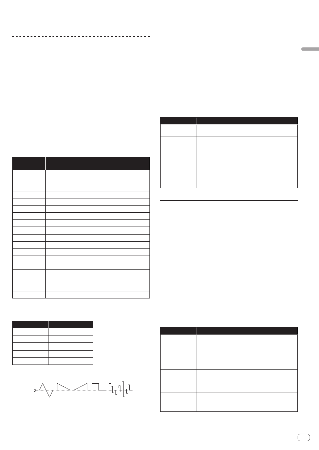
Shape
The LFO waveform can be selected from the following five types.
Setting value Waveform
Tri
Triangle
RevSaw
Reverse Sawtooth
Saw
Sawtooth
Square
Square
Random
Random
Triangle Sawtooth
Reverse
Sawtooth
Square Random
LFO waveshapes
- polarity +
! Both triangle and random waveforms (also called “sample and hold”)
generate modulation effects in both positive and negative directions.
! Sawtooth, reverse sawtooth, and square waves generate modulation
effects only in the positive direction.
! Here are some examples of LFO effects:
— Apply a triangle wave LFO to an oscillator to create vibrato.
— Apply a square wave LFO to an oscillator to create trills.
— To generate a white noise waveform with the LFO select
[Random] and set the [LFO]–[Frequency] to its maximum value.
Initial Amount
The [Initial Amt] parameter sets the amount of LFO modulation applied
to a selected destination.
Increasing the [Initial Amt] setting increases the amount of modulation
applied by the LFO.
Parameters in the [LFO DESTINATION] category
The parameters in this category are used to select the target (modulation
destination) of the LFO.
The following are the six modulation destinations. You can combine
them freely by setting each of them to [On]/[Off].
Parameter Explanation
Osc1 Freq
The oscillation frequency (pitch) of the Oscillator 1 is
modulated.
Osc2 Freq
The oscillation frequency (pitch) of the Oscillator 2 is
modulated.
Osc1-2PW
The pulse width is modulated when both the [Shape]
(waveform) parameters of the [Oscillator 1] and [Oscillator
2] categories are set to [Pulse] (pulse wave).
LP Cutoff
The cutoff frequency of the low-pass filter is modulated.
HP Cutoff
The cutoff frequency of the high-pass filter is modulated.
VCA
The volume is modulated.
SLIDER category
The slider serves the same function as a pitch or mod wheel. You can
control up to seven different parameters with the slider, and set different
amounts of modulation for each, using the [SLIDER DESTINATION]
category.
In addition, you can also use the slider to control filter envelope and
effects level, for even greater expressiveness.
SLIDER parameters
[SLIDER DESTINATION] is displayed as a category in the display.
Parameters in the [SLIDER DESTINATION] category
Select the target (slider destination) to be controlled with the slider.
There are seven destinations. You can set different amounts of
modulation for each destination.
! The value that you set for each parameter determines the maximum
amount of modulation that can be applied.
! Positive values apply modulation in the positive direction.
! Negative values apply modulation in the negative direction.
Parameter Explanation
Osc1 Freq
Sets the maximum amount of modulation applied to
Oscillator 1 frequency (pitch).
Osc2 Freq
Sets the maximum amount of modulation applied to
Oscillator 2 frequency (pitch).
LPF Amount
Sets the maximum amount of modulation applied to the
low-pass filter cutoff frequency.
HPF Amount
Sets the maximum amount of modulation applied to the
high-pass filter cutoff frequency.
LFO Amount
Sets the maximum amount of modulation applied by the
LFO.
FX1 Mix
Sets the maximum mix level of FX1.
FX2 Mix
Sets the maximum mix level of FX2.
Loading ...
Loading ...
Loading ...