2
En
Contents
How to read this manual
Thank you for buying this Pioneer DJ product.
Be sure to read this manual and the “Operating Instructions” (Quick
Start Guide) included with this unit. Both documents include important
information that you should understand before using this product.
! In this manual, the names of buttons, controls and terminals
indicated on the product, and program options appearing on the
unit display, etc., are indicated within square brackets ([ ]). (e.g.
[GLOBAL] button, [PHONES] terminal, [OSCILLATOR 1])
! Please note that the screens and specifications of the software
described in this manual as well as the external appearance and
specifications of the hardware are currently under development and
may differ from the final specifications.
! Please note that depending on the operating system version, web
browser settings, etc., operation may differ from the procedures
described in this manual.
Before starting
Features ........................................................................................................ 4
Part names and functions
Control panel ................................................................................................ 5
Rear Panel .................................................................................................... 7
Connections
Connecting inputs and outputs ................................................................. 8
Operation
Choosing and playing a program ............................................................... 9
Editing a program ........................................................................................ 9
Saving an edited program ........................................................................... 9
Initializing a program to create a sound from scratch ........................... 10
Using the sequencer ................................................................................. 10
Using the slider .......................................................................................... 11
Using the Quick Program function .......................................................... 11
Creating sounds and categories/parameters
OSCILLATOR category .............................................................................. 12
MIXER category ......................................................................................... 12
FILTER category ......................................................................................... 13
FILTER ENVELOPE category ..................................................................... 13
AMP ENVELOPE category ........................................................................ 14
GLIDE category .......................................................................................... 14
LFO (Low Frequency Oscillator) category ................................................ 14
SLIDER category ........................................................................................ 15
MODULATION category ............................................................................ 16
EFFECTS category ...................................................................................... 16
AFTERTOUCH category ............................................................................. 17
MISC PARAMETERS (Miscellaneous parameters) category ................ 17
ARPEGGIATOR/SEQUENCER category .................................................. 18
ARPEGGIATOR category ........................................................................... 18
SEQUENCER category .............................................................................. 18
Parameter list ............................................................................................. 19
Changing the unit settings ([GLOBAL SETTING])
[GLOBAL SETTING] menu items .............................................................. 21
Keyboard mode scale list .......................................................................... 23
Alternate tuning list ................................................................................... 24
Calibration .................................................................................................. 25
Using with external equipment
Connecting this unit to an external MIDI device or computer and
playing......................................................................................................... 26
Synchronizing and Playing this unit with an external MIDI device or
computer .................................................................................................... 26
Using the [TRIGGER IN] of this unit to control the play functions of this
unit .............................................................................................................. 27
MIDI implementation
MIDI Messages .......................................................................................... 28
NRPN (Non-Registered Parameter Number) Messages ....................... 29
Sysex Messages ......................................................................................... 30
MIDI Continuous Controllers (CC) Transmitted/Received ..................... 33
Program Parameter Data ......................................................................... 33
Block diagram
Block diagram (signal flow diagram) ....................................................... 36
Additional information
Troubleshooting ......................................................................................... 37
Precautions regarding our repair services .............................................. 38
About trademarks and registered trademarks ....................................... 38
Specifications............................................................................................. 38
3
En
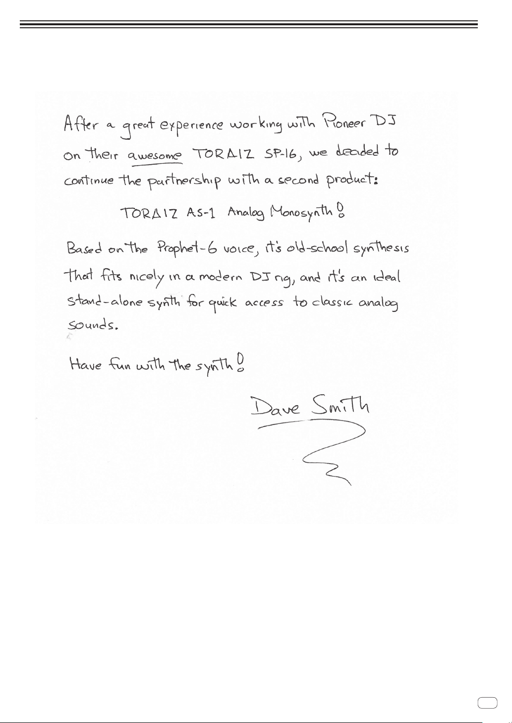
A message from Dave Smith

4
En
Before starting
Features
The TORAIZ AS-1 is a fully programmable monophonic analog
synthesizer that features discrete analog filters based on the acclaimed
Prophet-6 polyphonic synthesizer designed by Dave Smith Instruments
LLC. Its built-in 64-step sequencer and extensive library of preset sounds
make it an inspiring and expressive musical tool. And its easy-to-use
control panel packs a tremendous amount of sound-creation power and
versatility into a compact, robust metal chassis that is equally suited to
studio or stage.
Analog synthesizer circuit
The synthesizer circuitry of the TORAIZ AS-1 is based on the Prophet-6,
and was developed in cooperation with Dave Smith Instruments LLC.
The 4-pole, resonant low-pass filter gives the TORAIZ AS-1 the same
unique analog punch as the Prophet-6 and also provides it with powerful
tone-shaping and self-resonating capabilities.
Fully programmable synthesizer engine
All sounds can be saved as presets and accessed instantly in the studio
or on stage. Synthesizer parameters are clearly displayed in the high-
resolution OLED.
Extensive library of preset sounds
The factory presets are designed to cover a broad variety of musical
styles and genres. You can use them as is, or edit and save them
according to your preference.
64 step-sequencer and arpeggiator
The TORAIZ AS-1’s step-sequencer and arpeggiator are great tools for
phrase making and live performances. Since the 64-step sequencer is
capable of step input, you can instantly store the phrase you have just
come up with. Furthermore, you can change the sound rhythm and key
of the phrase made with the 64-step sequencer and arpeggiator in real
time, which will inspire you to create new phrases.
Intuitive interface and professional-
quality design
All TORAIZ AS-1 controls are arranged for easy, control-panel access in
much the same way as on DJ gear. This allows you to quickly and easily
tweak sounds in real time. And because it is compact and constructed
with a robust metal chassis, you can safely take it anywhere for music
production and live performance.

5
En
Part names and functions
Part names and functions
Control panel
onmlkji pf g h
1 3 4 5 6 72
8 9 a b c d e
1 SHIFT button
If a button has two functions, you can toggle between them by
turning the [SHIFT] button ON or OFF.
To turn on the [SHIFT] button, press and hold it so that it lights up. To
turn off the [SHIFT] button, just release it so that the light goes off.
See “Choosing and playing a program” (page 9).
2 GLOBAL button
Switches to global settings mode.
See “Changing the unit settings ([GLOBAL SETTING])” (page 21).
3 PROGRAM/BANK control
Switches programs.
To switch banks, turn on the [SHIFT] button before you turn the
control.
See “Choosing and playing a program” (page 9).
4 PARAM/CATEGORY control
Selects the parameter to be adjusted.
To switch between categories, turn on the [SHIFT] button before you
turn the [PARAM/CATEGORY] control.
See “Editing a program” (page 9).
5 Display
Displays bank number, program number, program name,
parameters, etc.
See “Choosing and playing a program” (page 9).
6 VALUE control
Adjusts the parameter/menu setting appearing in the display.
See “Editing a program” (page 9).
7 VOLUME control
Adjusts the audio output level.
See “Volume” (page 17) and “No sound or low sound” (page 37).
The volume of [AUDIO OUT] and [PHONES] output are linked.
When playing using headphones, be careful not to raise the volume
too much.
Depending on the [VOLUME] control setting, stimulusly loud sounds
may occur when you play the keyboard.
8 LPF CUTOFF control
Adjusts the cutoff frequency of the LPF (low-pass filter).
See “FILTER category” (page 13).
9 LPF RESONANCE control
Adjusts the resonance of the LPF (low-pass filter).
See “FILTER category” (page 13).
a HPF CUTOFF control
Adjusts the cutoff frequency of the HPF (high-pass filter).
See “FILTER category” (page 13).
b ENVELOPE ATTACK control
Adjusts the attack of the amplifier envelope and the filter envelope.
See “FILTER ENVELOPE category” (page 13).
c ENVELOPE DECAY/RELEASE control
Adjusts the decay and release of the amplifier envelope and the filter
envelope.
See “FILTER ENVELOPE category” (page 13).

6
En
d LFO FREQ/AMOUNT control
Adjusts the frequency of the LFO (Low Frequency Oscillator).
See “LFO (Low Frequency Oscillator) category” (page 14).
To adjust the amount of the LFO, turn on the [SHIFT] button before
you turn the [LFO FREQ/AMT] control.
See “SLIDER category” (page 15).
e FX ON/OFF button
Turns the effect On/Off.
See “EFFECTS category” (page 16).
f LATCH button
Holds the effect of the slider.
See “Using the slider” (page 11).
g Slider
Adjusts the effect of the slider.
See “Using the slider” (page 11).
h Keyboard
Use the keyboard to play the currently selected sound.
See “Choosing and playing a program” (page 9).
i OCTAVE DOWN button
Lowers the keyboard’s playing range an octave.
To lower it in semitone steps, turn on the [SHIFT] button before you
press the [OCTAVE DOWN] button.
See “Choosing and playing a program” (page 9) and
“OSCILLATOR category” (page 12).
j OCTAVE UP button
Raises the keyboard’s playing range an octave.
To raise it in semitone steps, turn on the [SHIFT] button before you
press the [OCTAVE DOWN] button.
See “Choosing and playing a program” (page 9) and
“OSCILLATOR category” (page 12).
k SEQUENCER record button
Puts the sequencer in the recording state.
See “Using the sequencer” (page 10).
l SEQUENCER play button
Plays the sequence.
See “Using the sequencer” (page 10).
m HOLD button
Turns On/Off the keyboard hold function.
See “Choosing and playing a program” (page 9) and
“ARPEGGIATOR category” (page 18).
n ARP button
Turns the arpeggiator function On/Off.
See “Choosing and playing a program” (page 9) and
“ARPEGGIATOR category” (page 18).
o CLOCK BPM/DIVIDE control
Adjusts BPM.
To adjust the tempo of the sequencer/arpeggiator, turn on the
[SHIFT] button before you turn the [CLOCK BPM/DIVIDE] control.
See “ARPEGGIATOR/SEQUENCER category” (page 18).
p CLOCK TAP button
Tap the [CLOCK TAP] button with your finger to set the BPM.
See “ARPEGGIATOR/SEQUENCER category” (page 18).
7
En
Part names and functions
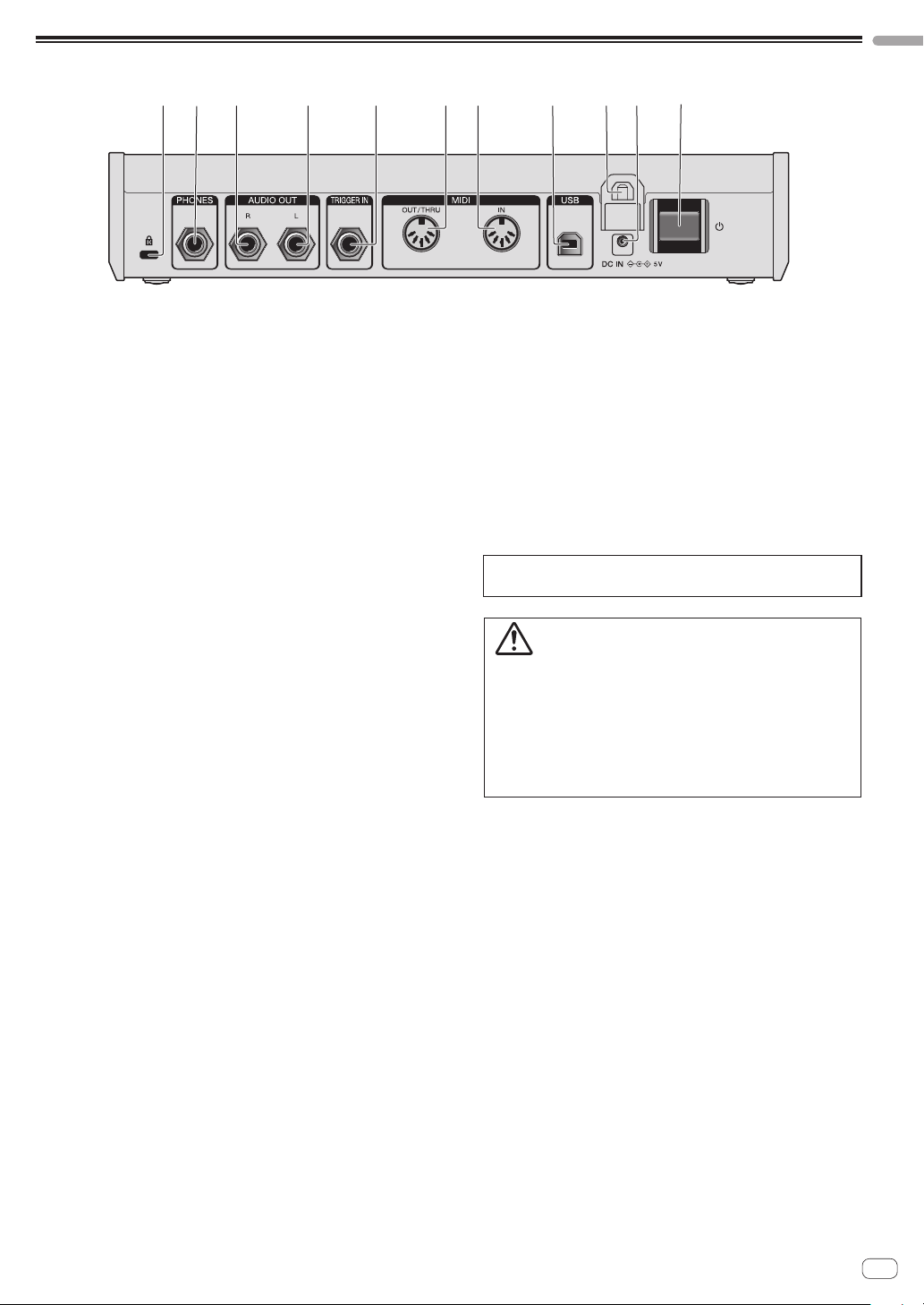
Rear Panel
21 3 4 5
8
b6 7
9
a
1 Kensington lock slot
2 PHONES output
Connect headphones.
3 AUDIO OUT R
Connect to an analog input terminal (right) of a power amplifier,
mixer, etc.
4 AUDIO OUT L
Connect to an analog input terminal (left) of a power amplifier, mixer,
etc.
5 TRIGGER IN
Connect a foot switch or a device that sends an audio signal to be a
trigger signal.
For detailed operational specifications of this terminal, see
“Changing the unit settings ([GLOBAL SETTING])” (page 21).
6 MIDI OUT/THRU
Connect to a device that receives MIDI signals from this unit.
7 MIDI IN
Connect to a device that sends MIDI signals to this unit.
8 USB-B terminal
Connect to your computer.
! USB hubs cannot be used.
! To optimize performance, connect this unit and computer directly
with a USB 2.0 compliant USB cable.
9 Cable hook
Connect the AC adapter cable here to prevent accidental
disconnection. See “How to use the cable hook” (page 8).
a DC IN terminal
Connect the AC adapter cable here.
b u button
Turns the power of this unit On/Off.
This switch is between off and on for this product.
Caution
Even if you turn off the unit by operating the switch/button of the unit or
remote control (if supplied) and the display goes out and the unit looks
like the same way as the unit being unplugged from the power, the power
is still supplied to the unit according to this product specifications. To
completely shut down the power supply, disconnect the plug (shut-off
device) of the power cord. In order to easily do so, set up the unit near the
power outlet so that you can access the power cord plug (shut-off device)
without difficulty. Keeping the unit plugged in the power outlet for an
extended period of time may cause a fire.
8
En
Connections
! Be sure to turn off the power and unplug the power cord from the power outlet whenever making or changing connections.
! Connect the power cord after all the connections between devices have been completed.
! Be sure to use the included power cord and AC adaptor.
! Refer to the operating instructions for components to be connected.
! Connect this unit and your computer directly using a USB cable.
— Use a USB cable which conforms to USB 2.0.
— USB hubs cannot be used.
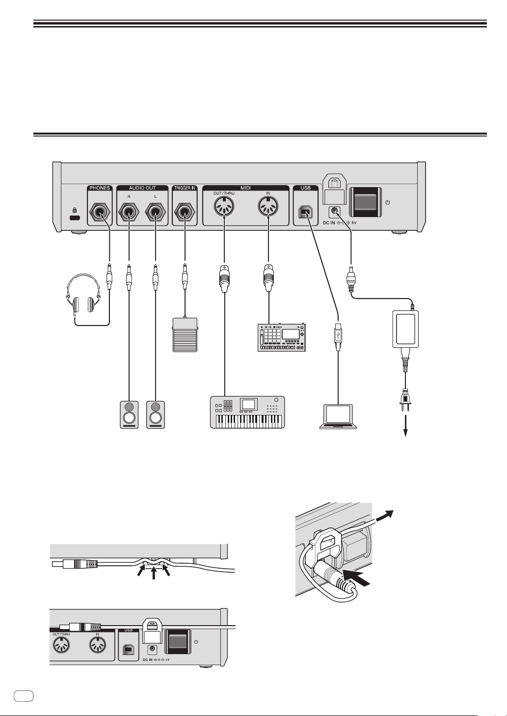
Connecting inputs and outputs
To power outlet
AC adaptor
(included)
ComputerSynthesizer, sound module, etc.Powered speakers
Foot switch
Headphones
MIDI keyboard,
sequencer, etc.
Power cord
(included)
How to use the cable hook
Connect the AC adapter cable to the cable hook to prevent accidental
disconnection.
! If the AC power adaptor cable is unplugged while you are playing the
synthesizer, the sound will stop abruptly.
1 Fit the connection cable of the AC adaptor into the
cable hook.
Secure the cable into place.
2 Connect the plug of the connection cable to the
[DC IN] terminal. If the cable on the left side of the
cable hook is too long, tighten it moderately.
Pull gently to tighten.
Plug in.
9
En
Operation
Operation
This chapter explains how to operate the unit from sound creation to playing.
For details on the categories, parameters and parameter values described in the operating procedures, see “Creating sounds and categories/
parameters” (page 12).
Choosing and playing a program
The TORAIZ AS-1 has ten banks ([F1]-[F5] and [U1]-[U5]) each of which
stores 99 programs. To recall the desired program, select a bank and a
program number in that order.
! The programs in the banks [F1]-[F5] are read-only and the programs
in the banks [U1]-[U5] are rewritable. Though you can edit any
program in any bank, you can only save a program to a user bank
[U1]-[U5].
(“F” represents “Factory bank” and “U” represents “User bank.”)
! When you purchase this product, the programs in the banks
[U1]-[U5] are identical to the programs in the banks [F1]-[F5].
About the last memory function
By selecting a program and pressing the [GLOBAL/WRITE] button
twice (press the [GLOBAL/WRITE] button to display the [GLOBAL
SETTING] screen and again press the [GLOBAL/WRITE] button to
return to the main screen), the selected program will be displayed
first on the main screen next time you turn on the unit.
1 Press the [u] button on the rear panel to turn on
the unit.
The main screen appears in the display.
2 Turn on the external devices connected to the
[AUDIO OUT] (e.g. powered speakers, power
amplifier, audio mixer, etc.).
3 Press and hold the [SHIFT] button and turn the
[PROGRAM/BANK] control to select a bank number.
The bank number in the display changes when you turn the control.
! If you press and hold the [SHIFT] button, it turns On only while you
are pressing the button. To turn it off, simply release the button.
Program number
Bank number
Program name
U5
Basic Program
Attack 0
P27
AMP ENVELOPE
120
BPM
:
4 Turn off the [SHIFT] button and turn the
[PROGRAM/BANK] control to select the desired
program.
The program number and program name in the display change when
you turn the control.
5 Play the keyboard.
The synthesizer plays the corresponding sound.
! If the [HOLD] button is On (lit), the sound plays continuously.
Each press of the [HOLD] button turns it On or Off in turn.
! If the [ARP] button is On (lit), any held notes are arpeggiated.
Each press of the [ARP] button turns it On or Off in turn.
! If you press the [OCTAVE UP] button/[OCTAVE DOWN] button while
performing the arpeggio play, you can raise/lower the scale by an
octave. To raise/lower in chromatic scale units, press and hold the
[SHIFT] button and press either button.
Editing a program
There are two ways to edit a program.
! Use the controls and buttons of the control panel to directly adjust
the main parameters (as shown in step 2 below).
! Choose the desired parameter shown in the display and adjust the
detailed parameters (as shown in steps 3 to 5 below).
For the operations of the buttons and controls, see “Part names and
functions” (page 5) and for details of the parameters, see “Creating
sounds and categories/parameters” (page 12).
1 Choose a program you wish to edit.
Follow steps 3 and 4 in “Choosing and playing a program” above.
2 Operate the [LPF CUTOFF], [LPF RES], [HPF
CUTOFF], [ENVELOPE ATTACK], [ENVELOPE DECAY/
REL], [LFO FREQ/AMT] controls and/or [FX] button.
The sound changes as you adjust the parameter.
3 Press and hold the [SHIFT] button and turn the
[PARAM/CATEGORY] control to choose the desired
category.
The category name in the display changes when you turn the control.
! See step 3 in “Choosing and playing a program” above for how to
turn on/off the [SHIFT] button.
Parameter name
Category name
Parameter value
U5
Basic Program
Attack 0
P27
AMP ENVELOPE
120
BPM
:
4 Turn off the [SHIFT] button and turn the [PARAM/
CATEGORY] control to choose the desired parameter
name.
The parameter name in the display changes when you turn the control.
5 Turn the [VALUE] control to adjust the parameter
value.
The sound changes as you adjust the parameter value shown in the
display.
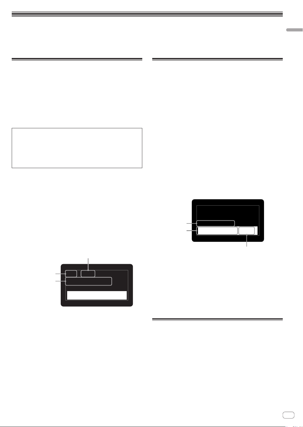
Saving an edited program
1 Press and hold the [SHIFT] button and press the
[GLOBAL/WRITE] button.
The following screen appears in the display and the [GLOBAL/WRITE]
button flashes. (The [SHIFT] button turns off automatically.)
! See step 3 in “Choosing and playing a program” above for how to
turn on/off the [SHIFT] button.
10
En
TB
U5
Basic Program
Attack 0
P27
Press Write to Save
or Hold to Cancel
2 If you wish to change the program name, turn the
[PARAM/CATEGORY] control to select the character
to be changed and turn the [VALUE] control to select
the desired character.
! You can choose from alphanumeric characters, symbols and a
blank.
! If you do not change the program name, this step is not necessary.
3 Press the [GLOBAL/WRITE] button again.
The currently selected program is overwritten by the edited program.
! To cancel saving, press the [HOLD] button instead of the [GLOBAL/
WRITE] button. The display returns to the main screen without
saving the edited program.
Initializing a program to create a
sound from scratch
When you wish to create a sound from scratch, you can use the “basic
program,” which is a simple, single-oscillator sound. To do this, select
a program and initialize it. You can then use this as a starting point for
sound creation.
1 Select a program you wish to initialize.
! Follow steps 3 and 4 in “Choosing and playing a program” (page
9).
2 Turn off the [SHIFT] button, and press the
[GLOBAL/WRITE] button.
The [GLOBAL SETTING] screen appears in the display and the[GLOBAL/
WRITE] button lights up.
! See step 3 in “Choosing and playing a program” (page 9) for how
to turn on/off the [SHIFT] button.
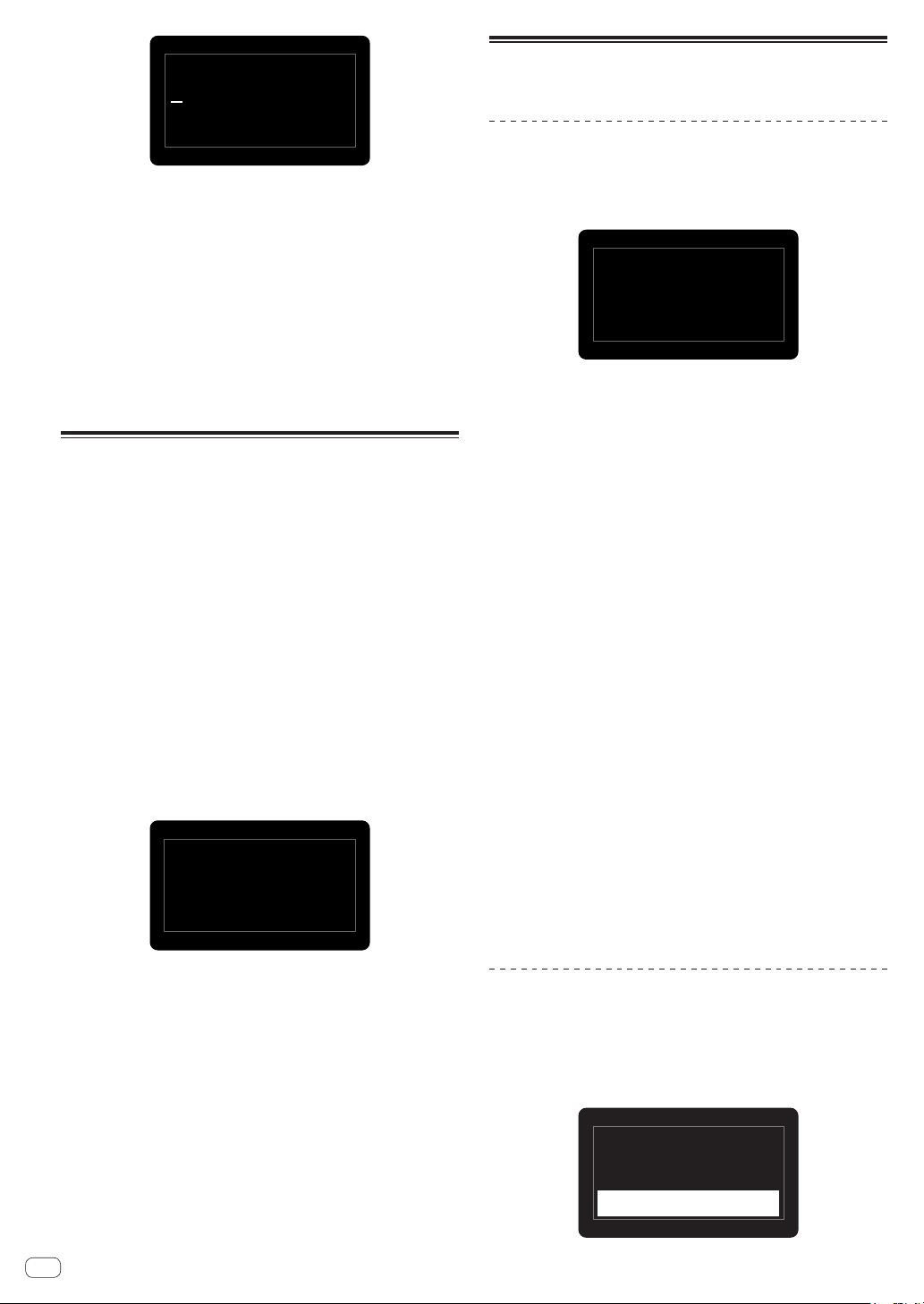
3 Turn the [PARAM/CATEGORY] control until the
[Basic Program] screen appears in the display.
When the [Basic Program] is selected, the [LATCH] button flashes.
23.
Press Latch to
0
Basic Program
Load Basic Patch
4 Press the [LATCH] button.
The currently selected program is initialized and the display returns to
the main screen.
! To create a sound, follow steps 2 to 5 in “Editing a program” (page
9).
For details such as parameter settings, see “Creating sounds and
categories/parameters” (page 12).
! To cancel initializing, press the [GLOBAL/WRITE] button again
instead of the [LATCH] button. The display returns to the main
screen without initializing the program.
Using the sequencer
This unit can create up to 64-step sequence patterns for each program.
Performing step recording
1 Press the [SEQUENCER record] button.
The [Record] screen appears in the display and the unit enters step
recording mode.
Note:–
–
Hit HOLD to Tie
Record
HOLD
sets Slew:
Off
120
BPM
:
Vel:–
–
Hit ARP to Rest
S
HIFT
+
2 Touch one of the keyboard keys.
The corresponding note is entered into a step, and the unit automatically
proceeds to the next step.
! Up to 64 steps can be entered.
! To enter a tie, press the [HOLD] button. When a note is tied,
the sound of the note you entered in the previous step plays
continuously.
! To enter a rest, press the [ARP] button.
! To switch [On]/[Off] of [Slew] of the step shown in the display, press
and hold the [SHIFT] button and press the [HOLD] button.
For how to turn on/off the [SHIFT] button, see step 3 in ““Choosing
and playing a program” (page 9).
3 Press the [SEQUENCER record] button.
The step recording ends.
! If you press the [SEQUENCER play] button while the unit is in step
recording state, it allows you to start sequencer playback as soon as
the step recording ends.
4 Press the [SEQUENCER play] button.
Playback of the entered sequence starts.
! If you touch a key of the keyboard while playing the sequence, the
pitch of the sequence shifts according to the scale of the key.
! To switch On/Off of [LOCK SEQUENCE], press and hold the [SHIFT]
button and press the [SEQUENCER] button.
— On: When you start playback of the sequence, the [SEQUENCER
play] button flashes. Even if you change the program, the
sequence pattern when [LOCK SEQUENCE] is switched On is
maintained.
— Off: When you start playback of the sequence, the [SEQUENCER
play] button lights up. When you change the program, the
sequence pattern also changes to the corresponding one.
! If you press and hold the [SHIFT] button and press the [TAP] button
while playing the sequence, the sequence jumps to the first step
(restarts).
Changing the number of steps you want
to play
1 Turn the [PARAM/CATEGORY] control to display
the [Length] parameter screen in the [SEQUENCER]
category.
U5
Basic Program
Length 64 Steps
P27
SEQUENCER
120
BPM
:
11
En
Operation
2 Turn the [VALUE] control to change the number of
steps to be played back.
The unit plays the sequence repeatedly (loop playback) according to the
number of steps shown in the display.
! To change the number of steps, hold down the [SHIFT] button and
turn the [VALUE] control.
! If you select [Length] less than the number of steps of the recorded
sequence, the playback forcibly returns to the first step after playing
the step specified by [Length].
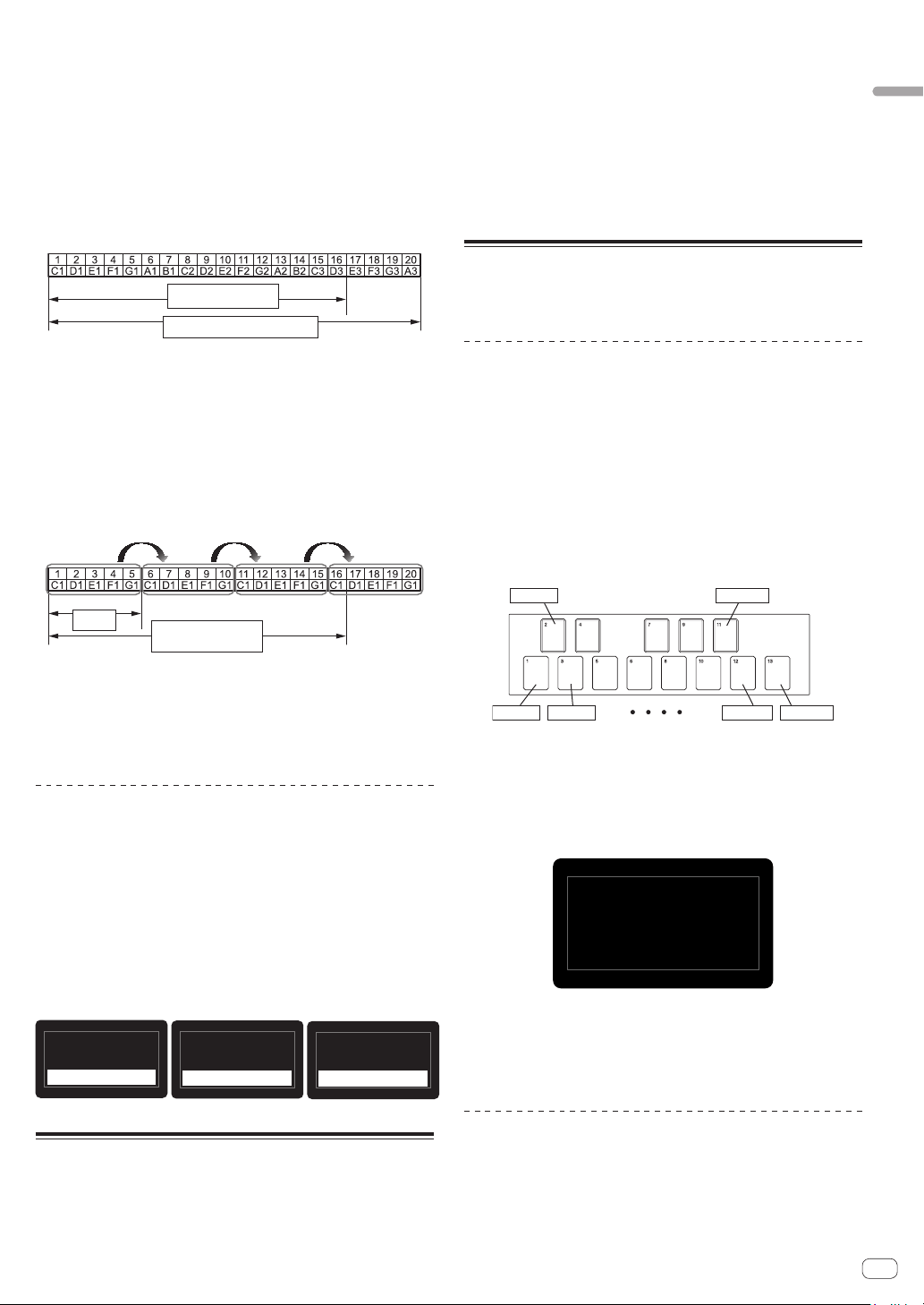
Example: When the number of steps in the recorded sequence is 20
and [Length] is set to [16 steps].
Step number
Number of steps
Recorded sequence
Entered notes
Loop playback range
The unit loops playback until the 16th step. Steps 17 to 20 are not
played, but the sequence pattern remains.
! If you select [Length] greater than or equal to the number of steps
of the recorded sequence, the unit plays the sequence pattern
repeatedly until it reaches [Length], then returns to the first step for
loop playback.
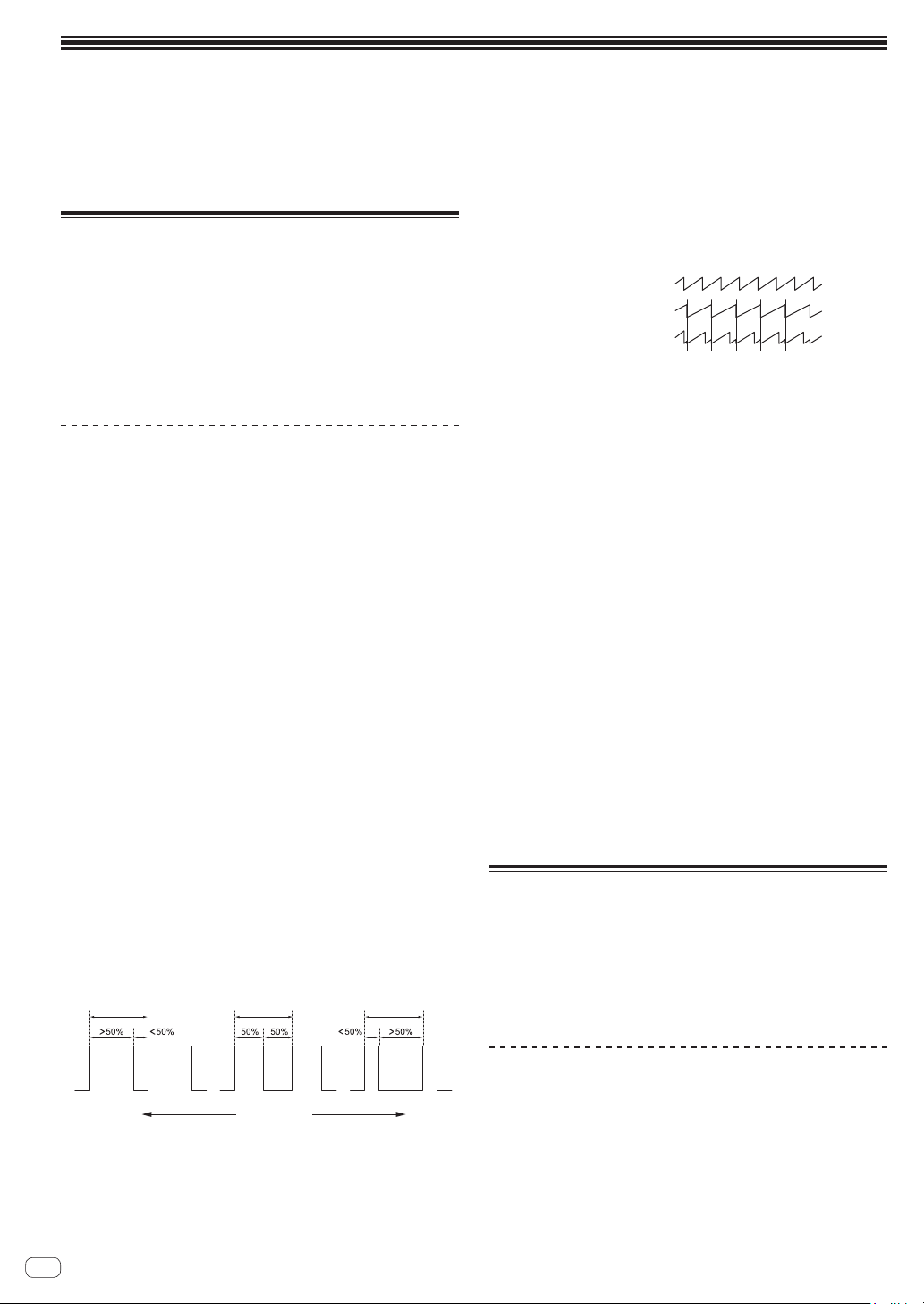
Example: When the number of steps of the recorded sequence is five
and [Length] is set to [16 steps].
Number
of steps
Loop playback range
Recorded
sequence
Entered notes
The unit plays the recorded five-step sequence pattern repeatedly
until the 16th step, then it forcibly returns to the first step to loop
playback.
! If you change the [Length] setting while playing a sequence, the
change will be reflected after the step specified by the previous
[Length] setting is played.
Changing the entered note setting
Each step has the following settings: [Note], [Vel], [Slew].
1 Turn the [PARAM/CATEGORY] control to display
the [Note], [Vel] or [Slew] parameter screen under
the [SEQUENCER] category of the step you wish to
change.
2 Turn the [VALUE] control to change the value of the
displayed parameter.
Changes in each parameter value are reflected instantly, regardless of
the playback/stop status of the sequence.
U5
Basic Program
Note 1
G
10
P27
SEQUENCER
120
BPM
:
U5
Basic Program
Vel 1 127
P27
SEQUENCER
120
BPM
:
U5
Basic Program
Slew 1
O
f f
P27
SEQUENCER
120
BPM
:
Using the slider
You can assign multiple parameters to the slider and dynamically
change the tone using the slider.
1 Turn the [PARAM/CATEGORY] control and choose
the parameter you wish to change using the slider
from the [SLIDER DESTINATION] category.
2 Turn the [VALUE] control to set the maximum value
of the parameter assigned to the slider.
3 Operate the slider.
! To make the slider hold its value even after you release your finger,
press the [LATCH] button so that the [LATCH] button turns on (lights
up).
Using the Quick Program function
The unit can assign up to 13 programs as Quick Programs to each
keyboard key and instantly recall them.
Assigning quick programs to the
keyboard keys
1 Press the [GLOBAL/WRITE] button.
The [GLOBAL SETTING] screen appears in the display.
2 Turn the [PARAM/CATEGORY] control to display the
[Quick Program] screen.
3 Turn the [VALUE] control to select a key to which
you wish to assign the quick program.
The numbers [Prog: 1] to [Prog: 13] correspond to the numbers on the
keyboard keys.
Prog: 2 Prog: 11
Prog: 1 Prog: 3 Prog: 12 Prog: 13
4 Press and hold the [SHIFT] button and turn the
[PROGRAM/BANK] control to select the bank number
that contains the program you wish to assign.
The bank number in the display changes.
! See step 3 in “Choosing and playing a program” (page 9) for how
to turn on/off the [SHIFT] button.
Prog:1
4
.
Q
uick
P
rogram
Ul P1
5 Turn off the [SHIFT] button and turn the
[PROGRAM/BANK] control to select the desired
program to assign to the selected key.
The program number in the display change.
Recalling the assigned Quick Programs
1 Press and hold the [SHIFT] and [LATCH] buttons and
touch the desired key.
This instantly switches to the program assigned in “Assigning quick
programs to the keyboard keys” above.
12
En
Creating sounds and categories/
parameters
This chapter explains the synthesis categories and parameters included in the program for creating sounds.
For details for how to change the categories, parameters and parameter values described here, see “Operation” (page 9).
OSCILLATOR category
The oscillator categories ([OSCILLATOR 1], [OSCILLATOR 2] and
[OSCILLATORS]) generate waveforms with various harmonic
configurations that form the basis of the sounds of this unit.
The unit has the two oscillators (Oscillator 1, Oscillator 2) and in
addition, a sub-oscillator of Oscillator 1 and an independent noise
generator.
Each of the two oscillators is capable of generating triangle, sawtooth,
and variable-width pulse waves. You can also continuously change these
three types of waveforms using the [Shape] parameter.
OSCILLATOR parameters
[OSCILLATOR 1], [OSCILLATOR 2] and [OSCILLATORS] are displayed
as categories in the display.
The following are the parameters displayed under one or two of the
categories.
Frequency
(Both the [OSCILLATOR 1] and [OSCILLATOR 2] categories have this
parameter.)
The [Frequency] parameter adjusts the basic pitch of the oscillator over
a range of five octaves.
! If you use the [OCTAVE UP] and [OCTAVE DOWN] buttons, the
range is nine octaves total.
Shape
(Both the [OSCILLATOR 1] and [OSCILLATOR 2] categories have this
parameter.)
The [Shape] parameter adjusts the waveform generated by the oscillator.
The waveform can change from triangular wave, sawtooth wave and
pulse wave continuously.
The three waveforms appear in the display as follows.
! Triangular wave: [Tri]
! Sawtooth Wave: [Saw]
! Pulse wave: [Pulse]
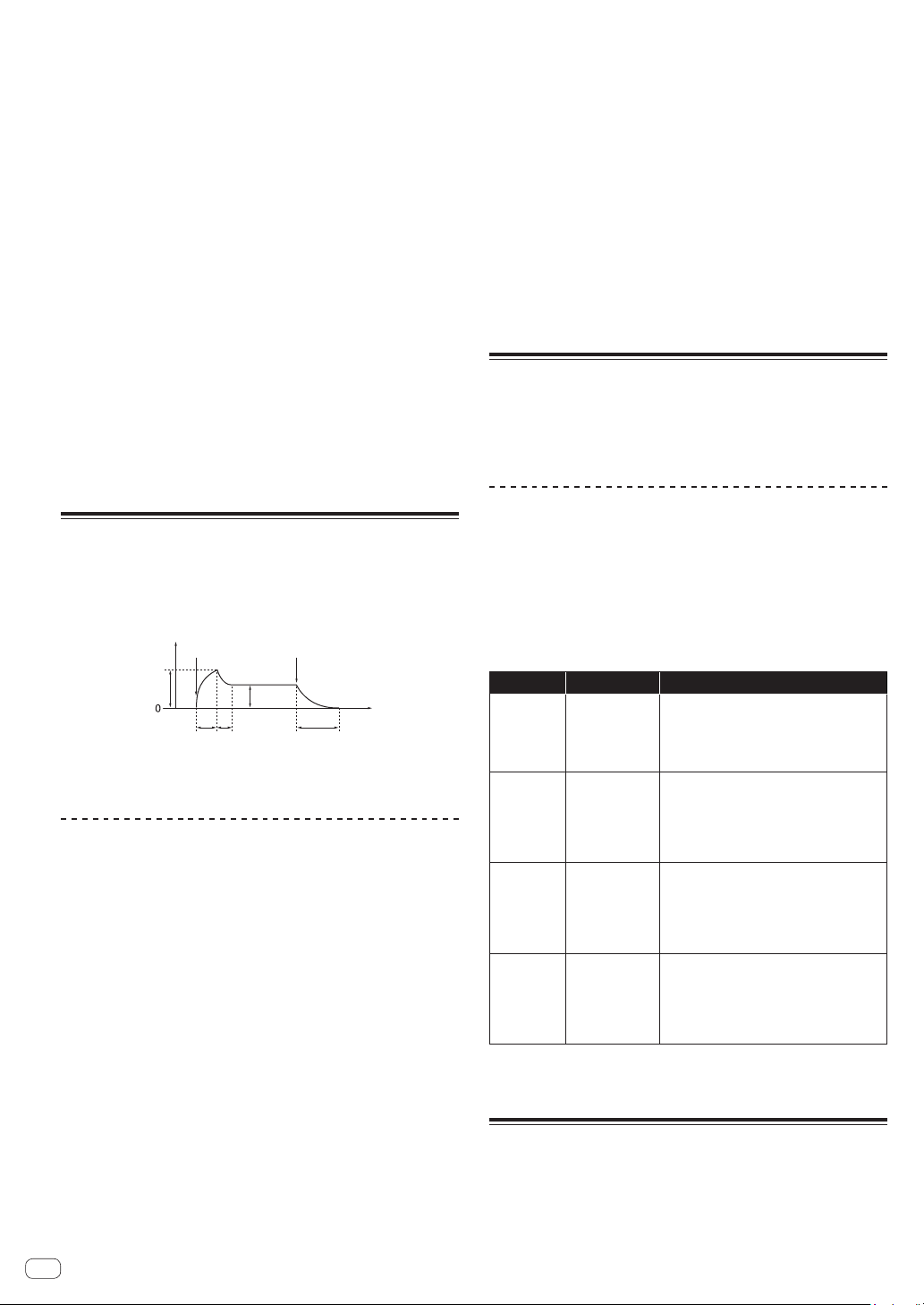
Pulse Width
(Both the [OSCILLATOR 1] and [OSCILLATOR 2] categories have this
parameter.)
The [Pulse Width] parameter adjusts the pulse width of the pulse wave.
! When [Pulse Width] is set to [127], the pulse wave becomes a
square wave (pulse width: 50%).
! When [Pulse Width] is set to [0] or [255], the duty ratio of the pulse
wave becomes 0% (pulse width: 0%), so the sound is not output.
Duty cycle (100%) Duty cycle (100%) Duty cycle (100%)
Set value: large
Set value: small
Square wave
Sync
(For [OSCILLATOR 1] category)
The [Sync] parameter sets the oscillator hard sync to [On]/[Off].
When the oscillator hard sync is set to [On], it forces Oscillator 1
to restart its cycle every time Oscillator 2 starts its cycle. This adds
harmonic overtones to the Oscillator 1 frequency, making a complex
waveform.
Oscillator 1
Oscillator1 synced to
Oscillator 2
Oscillator 2
Fine
(For [OSCILLATOR 2] category)
Fine tunes the pitch of Oscillator 2 up or down a quartertone. Slightly
detuning the pitches of Oscillator 1 and Oscillator 2 creates a thicker
sound.
Key Follow
(For [OSCILLATOR 2] category)
Set [Key Follow] to [On]/[Off].
When [Key Follow] is [On], the pitch of Oscillator 2 is controlled by the
keyboard.
! When using Oscillator 2 as an LFO (Low Frequency Oscillator)
source, it will continue to transmit at the frequency set in
[Frequency] by setting [Key Follow] to [Off].
! Even if [Key Follow] is set to [Off], modulations from other
modulation sources are enabled.
Low Freq
(For [OSCILLATOR 2] category)
When [Low Freq] is set to [On], Oscillator 2 can be used as an LFO.
Slop
(For [OSCILLATORS] category)
This parameter affects both Oscillator 1 and Oscillator 2.
Slop adds randomized detuning to both oscillators, giving the unit the
kind of slight tuning instability and “warmth” found on vintage analog
synthesizers.
! Small amounts of Slop will create a subtle vintage analog character.
Larger amounts will produce a more dramatically out-of-tune effect.
MIXER category
In the [MIXER] category, you can set the levels of the individual
oscillators.
To synthesize the waveform of each oscillator, you need to raise the
volume level of each parameter in the [MIXER] category.
! If the low-pass filter’s [RESONANCE] parameter is set high enough
to cause self-oscillation, the filter will produce a sine wave, even if all
the oscillators’ volumes are set to [0].
MIXER parameters
Osc1 Level
Sets the volume of Oscillator 1.
Osc2 Level
Sets the volume of Oscillator 2.
Sub Level
Sets the volume of the sub oscillator of Oscillator 1.

13
En
Creating sounds and categories/parameters
The sub oscillator generates a triangle wave that is one octave lower
than the pitch of Oscillator 1. Because a triangle wave has very few
harmonics, you can use the triangle sub octave to add weight to a sound
without changing its overall harmonic content.
Noise Level
Sets the volume of the white noise generated by the noise generator.
Noise is effective for making percussive sounds and sound effects such
as wind or ocean waves.
FILTER category
In the filter category ([LOW-PASS FILTER], [HIGH-PASS FILTER]), the
tone is processed by cutting or emphasizing the harmonic component of
the Oscillators.
This unit is equipped with a 4-pole (24 dB per octave) analog resonant
low-pass filter and a 2-pole (12 dB per octave) analog resonant high-pass
filter.
The low-pass filter attenuates the high frequencies, and the high-pass
filter attenuates the low frequencies. By using these two filters at the
same time, it also functions as a bandpass filter.
Also, you can emphasize a band of frequencies near the filter cutoff by
adjusting the resonance ([Resonance]) level.
FILTER parameters
[LOW-PASS FILTER] and [HIGH-PASS FILTER] are displayed as
categories in the display.
The following are the parameters displayed under either or both
categories.
Cutoff
(Both the [LOW-PASS FILTER] and [HIGH-PASS FILTER] categories have
this parameter.)
The [Cutoff] parameter adjusts the cutoff frequency of each filter.
The cutoff frequency is adjusted to the lower range when the set value of
the parameter decreases and to the higher range when it increases.
! As you decrease the value of the [LOW-PASS FILTER], you remove
the high frequences in the sound.
! As you increase the value of the [HIGH-PASS FILTER], you remove
the low frequences in the sound.
! The [FILTER ENVELOPE] allows you to control the filter’s cutoff
frequency over time.
Resonance
(Both the [LOW-PASS FILTER] and [HIGH-PASS FILTER] categories have
this parameter.)
The [Resonance] parameter adds a distinctive character to the sound by
emphasizing the overtones around the cutoff frequency.
! As the [Resonance] level is increased, the overtone component is
emphasized and the effect increases.
! The low-pass filter starts self-oscillation by increasing the
[Resonance] level, and the filter itself generates a sine wave.
! Setting [Resonance] to a high value when the Oscillators are also
set to a high value in the [MIXER] can cause distortion. Reduce
oscillator levels if necessary.
Key Amount
(Both the [LOW-PASS FILTER] and [HIGH-PASS FILTER] categories have
this parameter.)
[Key Amount] controls how the filter cutoff frequency is affected by the
keyboard. Settings are [Off/Half/Full].
! When set to [Full], the higher the note played on the keyboard, the
more the filter opens. The cutoff frequency changes are in semitone
units.
! When set to [Half], the higher the note played on the keyboard, the
more the filter opens. However, the cutoff frequency changes are in
half-semitone units.
! When set to [Off], playing higher or lower on the keyboard does not
affect filter frequency.
! When the low-pass filter is self-oscillating, you can play according
to the [Key Amount] setting in the [LOW-PASS FILTER] category as
follows.
— When set to [Full], you can play one octave twelve scale with the
oscillation sound (sine wave) of the filter.
— When set to [Half], you can play one octave twelve scale by
playing the keyboard two octaves.
Velocity
(Both the [LOW-PASS FILTER] and [HIGH-PASS FILTER] categories have
this parameter.)
When the [Velocity] parameter is set to [On], you can change the effect
of the filter envelope ([FILTER ENVELOPE]) to the cutoff frequency
depending on the velocity (strength of playing the keyboard).
! If you play the keyboard strongly, the amount of change in [LP
Amount] and [HP Amount] in the [FILTER ENVELOPE] category will
increase.
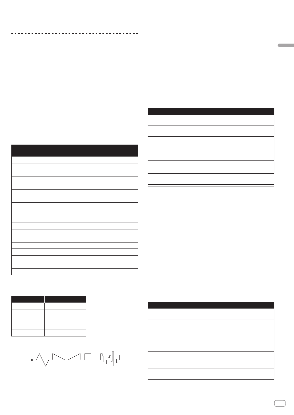
FILTER ENVELOPE category
The [FILTER ENVELOPE] is used to control the cutoff frequencies of
the two filters over time using the [Attack], [Decay], [Sustain], and
[Release] controls.
In general, sounds produced by an instrument are brighter at their
beginning (the attack stage) and grow mellower as they die out (the
decay and release stages). This is what the [FILTER ENVELOPE] is
designed to simulate.
Standard ADSR envelope
Cutoff
Note on
Sustain
level
Note off
Release time
Decay
time
Attack
time
Cutoff
Time
FILTER ENVELOPE parameters
LP Amount
The [LP Amount] parameter sets the amount of modulation from the
filter envelope to the low-pass filter. Higher amounts more dramatically
affect the cutoff frequency.
! Higher positive [LP Amount] settings cause the Filter Envelope to
more dramatically affect the filter cutoff frequency.
! Higher negative [LP Amount] settings cause the Filter Envelope to
be inverted and more dramatically affect the filter cutoff frequency in
the reverse direction.
Cutoff Cutoff
Note on Note off
Note on Note off
Time
Time
Plus direction Minus direction
HP Amount
The [HP Amount] parameter sets the amount of modulation from the
filter envelope to the high-pass filter. Higher amounts more dramatically
affect the cutoff frequency.
! Higher positive [HP Amount] settings cause the Filter Envelope to
more dramatically affect the filter cutoff frequency.
! Higher negative [HP Amount] settings cause the Filter Envelope to
be inverted and more dramatically affect the filter cutoff frequency in
the reverse direction.
14
En
Attack
The [Attack] parameter sets the attack time of the filter envelope.
This sets the length of time from note-on (pressing a key) until the filter
opens to the frequency set using the [Cutoff] parameter.
! The larger the setting value of [Attack], the longer it takes to reach
the maximum value.
Decay
The [Decay] parameter sets the decay time of the filter envelope.
This sets the time to reach the sustain level, after reaching the cutoff
frequency set in [Cutoff] through the attack stage.
! The larger the setting value of [Decay], the longer the time to reach
the sustain level becomes.
Sustain
The [Sustain] parameter sets the sustain level of the filter envelope.
This sets the cutoff frequency that is held while the sound is sustaining
through the decay time (while you are pressing the keyboard).
! The larger the setting value of [Sustain], the higher the sustain level.
! When [Sustain] is set to the maximum value, the [Decay] time has
no effect.
! When [Sustain] is set to the minimum value, the [Release] time has
no effect.
Release
The [Release] parameter sets the filter envelope release time.
This controls how quickly the filter closes after a note is released.
! The larger the setting value of [Release], the longer the decay time
until the filter closes.
AMP ENVELOPE category
The [AMP ENVELOPE] is used to control the overall loudness of a sound
over time using the [Attack], [Decay], [Sustain], and [Release] controls.
In general, sounds produced by an instrument change volume over time.
This is what the [AMP ENVELOPE] is designed to simulate.
Level
Note on Note off
Time
Release
time
Decay
time
Attack
time
Attack level
Sustain
level
Standard ADSR envelope
AMP ENVELOPE parameters
Amount
The [Amount] parameter sets the attack level (the maximum value of the
amplifier envelope) by the amplifier envelope.
Velocity
When the [Velocity] is set to [On], [Amount] of the amplifier envelope
can be changed by velocity (how hard you strike).
! The stronger you play the keyboard, the greater the change of
[Amount] (volume) becomes.
Attack
The [Attack] parameter sets the attack time of the amplifier envelope.
This sets the time from note-on (pressing a key) till it reaches the attack
level set in [Amount] (how fast the rising time to the crest is).
! The larger the setting value of [Attack], the longer it takes to reach
the attack level.
Decay
The [Decay] parameter sets the decay time of the amplifier envelope.
This sets the time to reach the sustain level, after reaching the attack
level.
! The larger the setting value of [Decay], the longer the time to reach
the sustain level becomes.
Sustain
The [Sustain] parameter sets the sustain level of the amplifier envelope.
This sets the volume that is held while the sound is sustaining through
the decay time (while you are pressing the keyboard).
! The larger the setting value of [Sustain], the higher the sustain level.
! When [Sustain] is set to the maximum value, the [Decay] time has
no effect.
! When [Sustain] is set to the minimum value, the [Release] time has
no effect.
Release
The [Release] parameter sets the amplifier envelope release time.
This sets the decay time until the envelope level becomes 0 from note-off
(the sound goes off).
! The larger the setting value of [Release], the longer the decay time
until the envelope level becomes 0.
GLIDE category
Glide (also called “portamento”) causes the pitch of a note to glide up or
down from the pitch of the previously played note.
The TORAIZ AS-1 provides four glide modes. You can select between
them to obtain the desired glide behavior.
GLIDE parameters
Rate
The [Rate] parameter sets the rate of the glide.
The larger the setting value of [GLIDE], the longer it takes to transition
from one note to the next.
If you set [GLIDE] to [0], glide will not be applied.
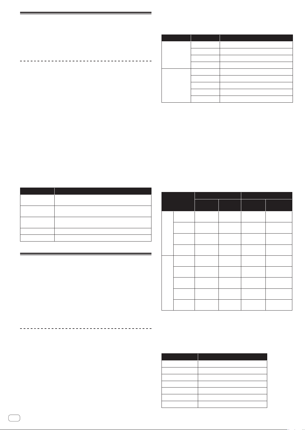
Mode
The following four modes can be selected.
Mode Formal name Explanation
FxRate
Fixed Rate
The glide rate is fixed.
! The time to transition between notes
varies with the interval between the notes;
the greater the interval, the longer the
transition time.
FxTime
Fixed Time
The glide time is fixed.
! The time required to transition between
notes is always constant regardless of the
interval between notes.
! Even if you release the keyboard once and
then press the keyboard, glide is applied.
FxRtA
Fixed Rate A
The effect is the same as [FxRate] but glide is
applied only when playing legato style.
! Legato playing style is a style of playing
by connecting notes (the technique of
playing a key/note while briefly continuing
to hold down the previous key/note).
FxTmA
Fixed Time A
The effect is the same as [FxTime] but glide is
applied only when playing legato style.
! Legato playing style is a style of playing
by connecting notes (the technique of
playing a key/note while briefly continuing
to hold down the previous key/note).
On/Off
Select [On]/[Off] of the glide function.
LFO (Low Frequency Oscillator)
category
The [LFO] is a low frequency oscillator that modulates a sound in a
periodic way.
The following are the typical examples of the effects using the [LFO].
15
En
Creating sounds and categories/parameters
! Vibrato: Periodic change in sound pitch
! Wah Wah: Periodic change in tone
! Tremolo: Periodic change in volume
LFO parameters
The following parameters appear under the [LFO] category in the display
except for “Parameters in the [LFO DESTINATION] category.”
Frequency
The [Frequency] parameter sets the oscillation frequency (modulation
speed) of the LFO.
! The larger the setting value of [Frequency], the higher the oscillation
frequency becomes (modulation speed gets faster).
! When [Sync] is set to [On], you can set the modulation speed
synchronized with BPM (tempo setting).
Sync
When the [Sync] parameter is set to [On], the LFO frequency is
synchronized to the BPMs of the arpeggiator, sequencer and MIDI clock.
! The LFO resets the waveform each time you press the keyboard
(except when playing legato style) and returns to the start point.
! When [Sync] is set to [On], the relationship between the [LFO]
category’s [Frequency] value and the [ARPEGGIATOR/SEQUENCER]
category’s [BPM] value (tempo setting) is as follows.
[Frequency]
value
Tempo Split note
32Q
BPM/32 Octuple whole note (Maxima)
16Q
BPM/16 Quadruple whole note (Longa)
8Q
BPM/8 Double whole note
6Q
BPM/6 Dotted whole note
4Q
BPM/4 Whole note
3Q
BPM/3 Dotted half note
1/2
BPM/2 Half note
1D
BPM/1.5 Dotted quarter note
1
BPM Quarter note
1T
BPM51.5
Quarter-note triplets
8D
BPM54/3
Dotted eighth note
8th
BPM52
Eighth note
8thT
BPM53
Eighth-note triplets
16thD
BPM58/3
Dotted 16th note
16th
BPM54
16th note
16thT
BPM56
16th-note triplets
32nd
BPM58
32nd note
32ndT
BPM512
32nd-note triplets
Shape
The LFO waveform can be selected from the following five types.
Setting value Waveform
Tri
Triangle
RevSaw
Reverse Sawtooth
Saw
Sawtooth
Square
Square
Random
Random
Triangle Sawtooth
Reverse
Sawtooth
Square Random
LFO waveshapes
- polarity +
! Both triangle and random waveforms (also called “sample and hold”)
generate modulation effects in both positive and negative directions.
! Sawtooth, reverse sawtooth, and square waves generate modulation
effects only in the positive direction.
! Here are some examples of LFO effects:
— Apply a triangle wave LFO to an oscillator to create vibrato.
— Apply a square wave LFO to an oscillator to create trills.
— To generate a white noise waveform with the LFO select
[Random] and set the [LFO]–[Frequency] to its maximum value.
Initial Amount
The [Initial Amt] parameter sets the amount of LFO modulation applied
to a selected destination.
Increasing the [Initial Amt] setting increases the amount of modulation
applied by the LFO.
Parameters in the [LFO DESTINATION] category
The parameters in this category are used to select the target (modulation
destination) of the LFO.
The following are the six modulation destinations. You can combine
them freely by setting each of them to [On]/[Off].
Parameter Explanation
Osc1 Freq
The oscillation frequency (pitch) of the Oscillator 1 is
modulated.
Osc2 Freq
The oscillation frequency (pitch) of the Oscillator 2 is
modulated.
Osc1-2PW
The pulse width is modulated when both the [Shape]
(waveform) parameters of the [Oscillator 1] and [Oscillator
2] categories are set to [Pulse] (pulse wave).
LP Cutoff
The cutoff frequency of the low-pass filter is modulated.
HP Cutoff
The cutoff frequency of the high-pass filter is modulated.
VCA
The volume is modulated.
SLIDER category
The slider serves the same function as a pitch or mod wheel. You can
control up to seven different parameters with the slider, and set different
amounts of modulation for each, using the [SLIDER DESTINATION]
category.
In addition, you can also use the slider to control filter envelope and
effects level, for even greater expressiveness.
SLIDER parameters
[SLIDER DESTINATION] is displayed as a category in the display.
Parameters in the [SLIDER DESTINATION] category
Select the target (slider destination) to be controlled with the slider.
There are seven destinations. You can set different amounts of
modulation for each destination.
! The value that you set for each parameter determines the maximum
amount of modulation that can be applied.
! Positive values apply modulation in the positive direction.
! Negative values apply modulation in the negative direction.
Parameter Explanation
Osc1 Freq
Sets the maximum amount of modulation applied to
Oscillator 1 frequency (pitch).
Osc2 Freq
Sets the maximum amount of modulation applied to
Oscillator 2 frequency (pitch).
LPF Amount
Sets the maximum amount of modulation applied to the
low-pass filter cutoff frequency.
HPF Amount
Sets the maximum amount of modulation applied to the
high-pass filter cutoff frequency.
LFO Amount
Sets the maximum amount of modulation applied by the
LFO.
FX1 Mix
Sets the maximum mix level of FX1.
FX2 Mix
Sets the maximum mix level of FX2.
16
En
MODULATION category
Many of the unique sounds associated with the Prophet-5 and Prophet-6
synthesizers were produced by creative use of “Poly Mod.” Poly Mod
allows you to use the Filter Envelope and Oscillator 2 as modulation
sources to create a wide range of complex harmonic effects, ranging
from FM (frequency modulation) to audio-range filter modulation.
MODULATION parameters
[MODULATION SOURCE] and [MODULATION DESTINATION] are
displayed as categories in the display.
Under these two categories, you can select the parameters for
generating the modulation effect and the degree of modulation to be
applied.
For the parameters selected in the [MODULATION DESTINATION]
category, you can set the modulation depth in either the plus direction or
the minus direction.
There are two parameters, Filter Envelope ([Filter Env]) and Oscillator
2 Amount ([Osc2 Amt]) in the [MODULATION SOURCE] category.
The amount of change to the modulation destinations by the two
modulations can be adjusted by setting each parameter’s value.
! When [Low Freq] of [OSCILLATOR 2] is set to [On] when using
Oscillator 2 as the modulation source, you can obtain an LFO-like
effect.
Parameters in the [MODULATION DESTINATION]
category
Select the target(s) to be modulated (modulation destination(s)) from the
following five parameters. By setting each parameter to [On] or [Off],
you can create a variety of combinations.
Parameter Explanation
Osc1 Freq
The oscillation frequency (pitch) of Oscillator 1 is
modulated.
Osc1 Shape
Waveform can be changed continuously by modulating the
[Shape] parameter in the [OSCILLATOR 1] category.
Osc1 PW
The pulse width is modulated when [Shape] (waveform) in
[Oscillator 1] is set to [Pulse] (pulse wave).
LP Cutoff
The cutoff frequency of the low-pass filter is modulated.
HP Cutoff
The cutoff frequency of the high-pass filter is modulated.
EFFECTS category
This unit is equipped with two high-quality 24-bit 48 kHz digital effectors
(FX 1, FX 2). This allows you to add a delay, chorus, phaser, etc. without
the need for external effects devices.
Although the effects are digitally processed, the main signal path is
analog. The effects operate on a separate path and are converted to
analog, and then mixed into the final signal path.
Effects settings are saved with each program.
Time-based effects such as delay can be tempo-synced to the
arpeggiator, sequencer, and MIDI clock and a repetitive effect synced to
the chosen BPM can be obtained.
EFFECTS parameters
FX On/Off
The [FX On/Off] parameter turns on or off the entire [EFFECTS]
parameters.
! This parameter is linked with the [FX ON/OFF] button on the control
panel.
! The [FX On/Off] parameter (or the [FX ON/OFF] button) enables
and disables both FX1 and FX2, using a true bypass, ensuring a pure
analog signal path.
FX Type
(The [FX1 Type] and [FX2 Type] parameters appear when selecting in
the display.)
You can select the desired effect type each for the [FX1 Type] and [FX2
type] parameters as shown in the following table. The effect types
selected here will be edited by the parameters as shown in the table
below.
Parameter Effect type Explanation
FX1 Type
Off
Disables FX1.
BBD
Vintage BBD (Bucket-Brigade Delay)
Dist
Distortion
RingMod
Vintage Ring Modulator
FX2 Type
Off
Disables FX2.
Chorus
Vintage Chorus
PhaserH
Vintage Phaser (High Resonance)
PhaserL
Vintage Phaser (Low Resonance)
PhaserM
Vintage Phaser (Maestro phaser emulation)
FX Mix
(The [FX1 Mix] and [FX2 Mix] parameters appear when selecting in the
display.)
The [FX1 Mix] and [FX2 Mix] parameters set the mix balance between
the effect sound (wet sound) and the original sound (dry sound).
! Setting the parameter to the minimum value results in 100% dry
sound and setting the parameter to the maximum value results in
100% wet sound.
! Effected signals are processed in send/return paths, which ensures
pure analog signal paths for the unprocessed sounds.
FX Param
The group of the parameters to adjust the effect of the selected effect
type. Each effect has two adjustable parameters, as shown in the table
below.
Effect type
Parameter 1 Parameter 2
Displayed
as
Adjusting
Effect
Displayed
as
Adjusting
Effect
FX1
Type
Off
FX1
Param 1
n/a
FX1
Param 2
n/a
BBD BBD Time
Delay time
BBD Fdbk
Feedback
amount
Dist Dist Drive
Distortion
amount
Dist Tone
Tone
RingMod
Ring Md
Tune
Frequency
Ring Mod
KeyF
Tracking
FX2
Type
Off
Fx2
Param 1
n/a
FX2
Param 2
n/a
Chorus
Chorus
Rate
Rate
Chorus
Dpth
Depth
PhaserH
Phaser
Rate
Rate
Phaser
Dpth
Depth
PhaserL
Phaser
Rate
Rate
Phaser
Dpth
Depth
PhaserM
Phaser
Rate
Rate
Phaser
Dpth
Depth
FX1 Sync
When the [FX1 Sync] parameter is set to [On] and [BBD] is selected as
an effect type, [BBD Time] (delay time) can be synchronized with the
arpeggiator, sequencer and MIDI clock. [BBD Time] is changed to and
displayed as [Sync Time] which operates according to the values shown
in the following table.
Setting value Delay time
64th
1/16 beats (64th note)
32nd
1/8 beats (32nd note)
1/32 D
3/16 beats (dotted 32nd note)
16th
1/4 beats (sixteenth note)
1/16 D
3/8 beats (dotted 16th note)
8th
1/2 beats (eighth note)
8th D
3/4 beats (dotted eighth note)
17
En
Creating sounds and categories/parameters
Setting value Delay time
Qrtr
1 beat (quarter note)
Qrtr D
1.5 beats (dotted quarter note)
Half
2 beats (half note)
Half D
Three beats (dotted half note)
AFTERTOUCH category
Aftertouch is a performance feature that allows you to add modulation to
a sound by applying additional pressure to a key after the key is already
down.
There are six parameters that can control the amount of modulation
applied with aftertouch.
In the display, set the [Amount] parameter in the [AFTERTOUCH]
category to set the aftertouch amount. Then, set each parameter in the
[AFTERTOUCH DESTINATION] category to [On]/[Off] apply aftertouch
to the desired parameter(s).
AFTERTOUCH parameters
[AFTERTOUCH] and [AFTERTOUCH DESTINATION] are displayed as
categories in the display.
Amount
(This is the parameter in the [AFTERTOUCH] category.)
The [Amount] parameter sets the aftertouch depth.
! If you increase the [Amount] value in the plus direction, aftertouch
effect will increase in the plus direction.
! If you increase the [Amount] value in the minus direction, aftertouch
effect will increase in the minus direction or decrease depending on
the parameter.
Parameters in the [AFTERTOUCH DESTINATION] category
Select the target(s) to which you wish to apply aftertouch (aftertouch
destination(s)).
The following six parameters can be selected as aftertouch destinations.
Use [On/Off] to enable aftertouch for a specific parameter.
Parameter Explanation
Osc 1 Freq
Changes the oscillation frequency (pitch) of Oscillator 1.
! If the [Amount] value is set in the plus direction, the
pitch of Oscillator 1 will rise as you further press down the
keyboard.
! If the [Amount] value is set in the minus direction, the
pitch of Oscillator 1 will lower as you further press down
the keyboard.
Osc 2 Freq
Changes the oscillation frequency (pitch) of Oscillator 2.
! If the [Amount] value is set in the plus direction, the
pitch of Oscillator 2 will rise as you further press down the
keyboard.
! If the [Amount] value is set in the minus direction, the
pitch of Oscillator 2 will lower as you further press down
the keyboard.
LP Cutoff
Changes the cutoff frequency of the low-pass filter.
! If the [Amount] value is set in the plus direction, the cutoff
frequency will rise as you further press down the keyboard.
! If the [Amount] value is set in the minus direction, the
cutoff frequency will lower as you further press down the
keyboard.
! If the [Cutoff] value is set to the maximum or the
minimum, aftertouch may have no effect depending on the
[Amount] value.
HP Cutoff
Changes the cutoff frequency of the high-pass filter.
! If the [Amount] value is set in the plus direction, the cutoff
frequency will rise as you further press down the keyboard.
! If the [Amount] value is set in the minus direction, the
cutoff frequency will lower as you further press down the
keyboard.
! If the [Cutoff] value is set to the maximum or the
minimum, aftertouch may have no effect depending on the
[Amount] value.
Parameter Explanation
VCA
Changes the volume.
! If the [Amount] value is set in the plus direction, the
volume will increase as you further press down the
keyboard.
! If the [Amount] value is set in the minus direction, the
volume will decrease as you further press down the
keyboard.
! If the [Amount] and [Sustain] values in the [AMP
ENVELOPE] category are set to the maximum, aftertouch
may have no effect.
LFO Amt
Changes the [Initial Amt] value in the [LFO] category.
! If the [Amount] value is set in the plus direction, the effect
of the LFO will increase as you further press down the
keyboard.
! Even if the [Amount] value is set in the minus direction,
the effect of the LFO will increase, but the LFO waveform is
inverted (reversed phase).
MISC PARAMETERS (Miscellaneous
parameters) category
You can set various important functions using the parameters in the
[MISC PARAMETERS] category.
Parameters in the [MISC PARAMETERS]
category
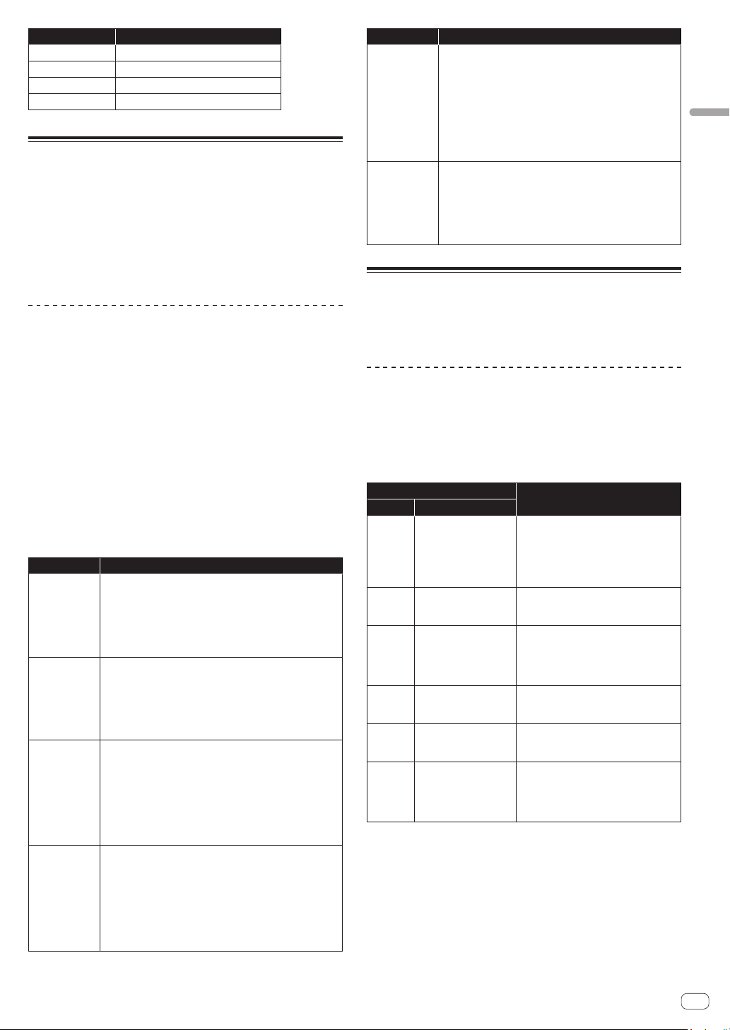
KeyMode
The [KeyMode] parameter sets the key assignment (also called “note
priority”). This determines what note has priority when more than one
note is played on the keyboard or via MIDI.
[KeyMode] parameter
Operation
Value Meaning
Low
Low-note priority
(Single trigger)
It is the most popular method when using
a vintage synthesizer.
It is often used to play trill while holding
down one of the keys. The lower note
is played without the envelope being
retriggered.
Hi
High-note priority
(Single trigger)
When playing trill by holding down one of
the keys, the higher note is played without
the envelope being retriggered.
Last
Last-note priority
(Single trigger)
When playing trill by holding down one
of the keys, the last pressed key is played
without the envelope being retriggered
regardless of whether or a lower note or a
higher note is played..
LowR
Low-note priority +
retrigger
(Multi trigger)
When playing trill by holding down
a lower note, the envelope is always
retriggered.
HiR
High-note priority +
retrigger
(Multi trigger)
When playing trill by holding down a
higher note, the envelope is always
retriggered.
LastR
Last-note priority +
retrigger
(Multi trigger)
When playing trill by holding down one
of the keys, the pitch of the last pressed
key is played with the envelope being
retriggered whether or a lower note or a
higher note is played..
Volume
The volume of each program can be set independently. This is useful for
ensuring that your sounds have roughly the same volume from program
to program.
PitchbndRange
You can set the pitch bend range in semitone unit up to +/– 12
semitones (1 octave).
18
En
ARPEGGIATOR/SEQUENCER category
The arpeggiator and sequencer have the following features:
! The sequencer has a maximum of 64-steps, with the ability to add
ties and rests.
! The arpeggiator has a range of three octaves and several operating
modes including, UP, DOWN, UP & DOWN, etc.
ARPEGGIATOR/SEQUENCER parameters
BPM
The [BPM] (Beat Per Minute) parameter sets the tempo at which
the arpeggiator and sequencer operate when [MIDI Clock Mode] of
[GLOBAL SETTING] is set to master mode ([Off]/[Master]).
! When [MIDI Clock Mode] is set to slave mode ([Slave]/[Slave Thru]/
[Slave No S/S]), this [BPM] setting is ignored and synchronizes with
the external MIDI clock.
! The [BPM] setting is linked with the [CLOCK TAP] button on the
control panel, and the [CLOCK TAP] button flashes according to the
set tempo.
! You can also set [BPM] by tapping the [CLOCK TAP] button on the
control panel at least three times at your desired tempo, or by turning
the [CLOCK BPM/DIVIDE] dial.
! The setting range of [BPM] is between 30 and 250.
! The [BPM] setting will affect the frequency of the LFO and the
BBD effect when [Sync] of the [LFO] category or [FX 1 Sync] of the
[EFFECTS] category is set to [On].
TimeDiv
Sets the time value for each sequencer/arpeggiator step relative to the
BPM. This value applies to both internal and external clock sources. The
following table lists the values:
[TimeDiv]
setting value
[BPM] setting
(tempo)
Split note
2 BPM/2
Half note
4 BPM
Quarter note
8D BPM x2
Dotted eighth note
8 BPM x2
Eighth note
8S BPM x2
Eighth note (Swing)
8T BPM x3
Eighth note triplets
16 BPM x4
16th note
16S BPM x4
16th note (Swing)
16T BPM x6
16th note triplets
32 BPM x8
32nd note
ARPEGGIATOR category
When you turn on the arpeggiator and hold a chord on the keyboard, the
TORAIZ AS-1 will play a pattern based on the individual notes held.
You can choose a mode (up, down, random, etc.), an octave range (1, 2,
or 3), and a tempo.
! If you turn on the [HOLD] button on the control panel, the arpeggio
continues to play even if you release your fingers from the keyboard.
When the [HOLD] button is On, the arpeggio performance will be as
follows.
— If you play a new chord, the current arpeggio play is replaced by
the new one.
— If you press another key while pressing down more than one key,
the pitch of the newly pressed key will be added to the current
arpeggio by the auto latch feature.
! The sequencer cannot be used while the arpeggiator function is On.
ARPEGGIATOR parameters
On/Off
The [On/Off] parameter turns on/off the arpeggiator function.
This parameter is linked with the [ARP] button on the control panel.
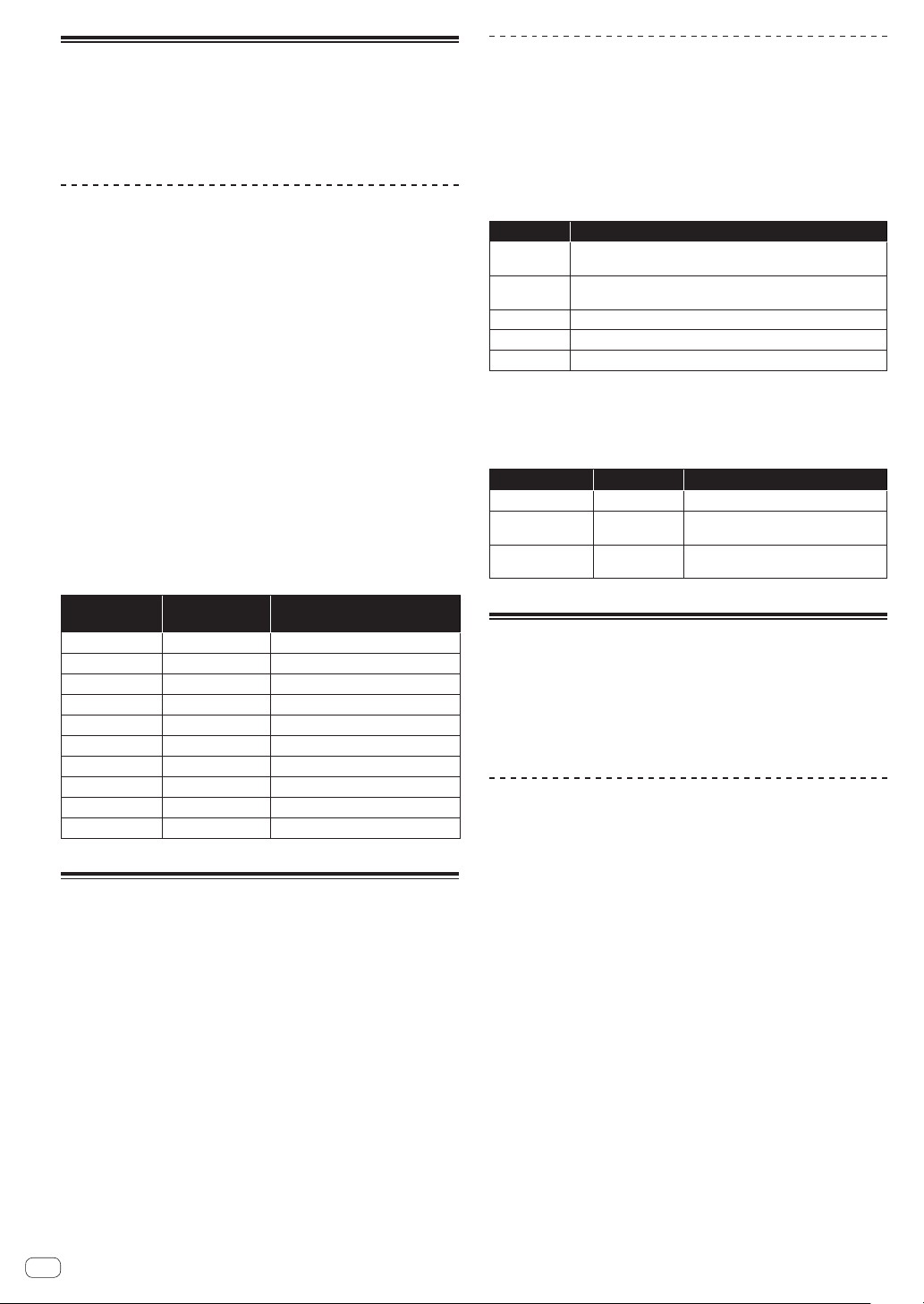
Mode
The [Mode] parameter sets the behavior of the arpeggiator
corresponding to the played chord.
You can choose from the following five modes.
Mode Arpeggio behavior
Up
A played chord is arpeggiated from the lowest pitch to higher
pitches.
Down
A played chord is arpeggiated from the highest pitch to lower
pitches.
Up+Dwn
Repeatedly plays from lowest to highest and back to lowest.
Random
The notes of a chord are played in random order.
Assign
Plays notes in the order the keys were pressed.
Range
The [Range] parameter sets the range from one octave to three octaves
in which a chord is arpeggiated.
The settings and arpeggio behavior are as follows.
[Range] setting In octave unit Arpeggiated behavior
10ct
1 octave Only the held notes are arpeggiated.
20ct
2 octaves
The held notes and the same notes one
octave above them arpeggiate.
30ct
3 octaves
The held notes and the same notes one
and two octave above them arpeggiate.
SEQUENCER category
The sequencer allows you to create a single sequence of up to 64 steps,
including rests and ties. Saving a sound saves any sequence you have
created for it.
! When the sequencer is playing, the arpeggiator is disabled.
! For how to create sequencer patterns and play them, see “Using the
sequencer” (page 10).
SEQUENCER parameters
Length
The [Length] parameter sets the number of steps in the sequence.
! Up to 64 steps can be set.
Note
The [Note] parameter sets notes for each step.
! From [C0] to [C10] can be set.
! See “Using the sequencer” (page 10) for adding ties.
Vel
The [Vel] parameter sets the velocity for each step.
! To create a rest, set the value to [Rest].
Slew
The [Slew] sets the slur setting to [On]/[Off].
When set to [On], you can smoothly connect adjacent different pitches.
19
En
Creating sounds and categories/parameters
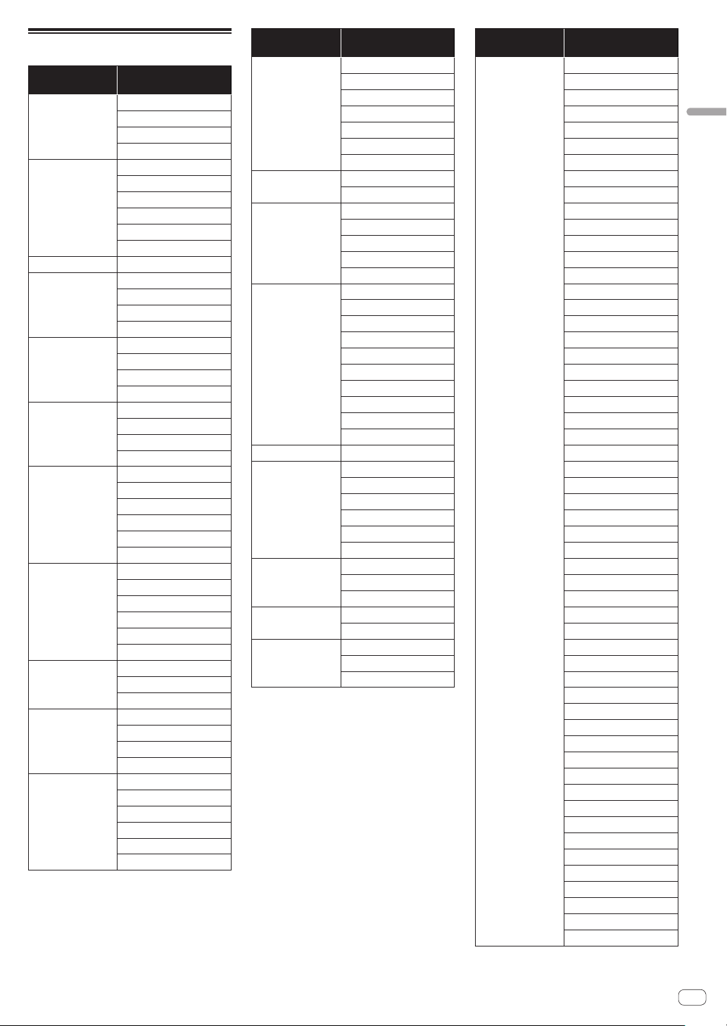
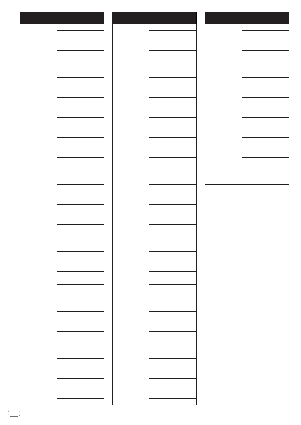
Parameter list
Category name
in the display
Parameter
OSCILLATOR 1 Frequency
Shape
Pulse Width
Sync
OSCILLATOR 2 Frequency
Fine
Shape
Pulse Width
Key Follow
Low Freq
OSCILLATORS Slop
MIXER Osc1Level
Osc2Level
Sub Level
Noise Level
LOW-PASS FILTER Cutoff
Resonance
Key Amount
Velocity
HIGH-PASS
FILTER
Cutoff
Resonance
Key Amount
Velocity
FILTER ENVELOPE LP Amount
HP Amount
Attack
Decay
Sustain
Release
AMP ENVELOPE Amount
Velocity
Attack
Decay
Sustain
Release
GLIDE Rate
Mode
On/Off
LFO Frequency
Sync
Shape
Initial Amt
LFO
DESTINATION
Osc 1 Freq
Osc 2 Freq
Osc 1-2 PW
LP Cutoff
HP Cutoff
VCA
Category name
in the display
Parameter
SLIDER
DESTINATION
Osc 1 Freq
Osc 2 Freq
LPF Amount
HPF Amount
LFO Amount
FX1 Mix
FX2 Mix
MODULATION
SOURCE
Filter Env
Osc 2 Amt
MODULATION
DESTINATION
Osc 1 Freq
Osc 1 Shape
Osc 1 PW
LP Cutoff
HP Cutoff
EFFECTS FX On/Off
FX1 Type
FX1 Mix
FX1 Param 1
FX1 Param 2
FX1 Sync
FX2 Type
FX2 Mix
FX2 Param 1
FX2 Param 2
AFTERTOUCH Amount
AFTERTOUCH
DESTINATION
Osc 1 Freq
Osc 2 Freq
LP Cutoff
HP Cutoff
VCA
LFO Amt
MISC
PARAMETERS
Key Mode
Volume
Pitchbnd Range
ARPEGGIATOR/
SEQUENCER
BPM
TimeDiv
ARPEGGIATOR On/Off
Mode
Range
Category name
in the display
Parameter
SEQUENCER Length
Note 1
Vel 1
Slew 1
Note 2
Vel 2
Slew 2
Note 3
Vel 3
Slew 3
Note 4
Vel 4
Slew 4
Note 5
Vel 5
Slew 5
Note 6
Vel 6
Slew 6
Note 7
Vel 7
Slew 7
Note 8
Vel 8
Slew 8
Note 9
Vel 9
Slew 9
Note 10
Vel 10
Slew 10
Note 11
Vel 11
Slew 11
Note 12
Vel 12
Slew 12
Note 13
Vel 13
Slew 13
Note 14
Vel 14
Slew 14
Note 15
Vel 15
Slew 15
Note 16
Vel 16
Slew 16
Note 17
Vel 17
Slew 17
Note 18
Vel 18
Slew 18
20
En
Category name
in the display
Parameter
Note 19
Vel 19
Slew 19
Note 20
Vel 20
Slew 20
Note 21
Vel 21
Slew 21
Note 22
Vel 22
Slew 22
Note 23
Vel 23
Slew 23
Note 24
Vel 24
Slew 24
Note 25
Vel 25
Slew 25
Note 26
Vel 26
Slew 26
Note 27
Vel 27
Slew 27
Note 28
Vel 28
Slew 28
Note 29
Vel 29
Slew 29
Note 30
Vel 30
Slew 30
Note 31
Vel 31
Slew 31
Note 32
Vel 32
Slew 32
Note 33
Vel 33
Slew 33
Note 34
Vel 34
Slew 34
Note 35
Vel 35
Slew 35
Note 36
Vel 36
Slew 36
Note 37
Vel 37
Slew 37
Category name
in the display
Parameter
Note 38
Vel 38
Slew 38
Note 39
Vel 39
Slew 39
Note 40
Vel 40
Slew 40
Note 41
Vel 41
Slew 41
Note 42
Vel 42
Slew 42
Note 43
Vel 43
Slew 43
Note 44
Vel 44
Slew 44
Note 45
Vel 45
Slew 45
Note 46
Vel 46
Slew 46
Note 47
Vel 47
Slew 47
Note 48
Vel 48
Slew 48
Note 49
Vel 49
Slew 49
Note 50
Vel 50
Slew 50
Note 51
Vel 51
Slew 51
Note 52
Vel 52
Slew 52
Note 53
Vel 53
Slew 53
Note 54
Vel 54
Slew 54
Note 55
Vel 55
Slew 55
Note 56
Vel 56
Slew 56
Category name
in the display
Parameter
Note 57
Vel 57
Slew 57
Note 58
Vel 58
Slew 58
Note 59
Vel 59
Slew 59
Note 60
Vel 60
Slew 60
Note 61
Vel 61
Slew 61
Note 62
Vel 62
Slew 62
Note 63
Vel 63
Slew 63
Note 64
Vel 64
Slew 64
21
En
Changing the unit settings ([GLOBAL SETTING])
Changing the unit settings ([GLOBAL
SETTING])
Global settings are parameters that affect all programs. These include settings such as Master Tune, MIDI Channel, MIDI Clock, and others.
To change Global settings, press the [GLOBAL/WRITE] button and the [GLOBAL SETTING] screen appears. Any change in [GLOBAL SETTING] will be
reflected in all programs.
[GLOBAL SETTING] menu items
No. Menu item (in the display) Setting value/range Explanation
1 Master Coarse -12 to 0* to +12
Sets the sound pitch.
! You can adjust the pitch in chromatic increments from the center [0] in
the range of minus one octave to plus one octave.
2 Master Fine -50 to 0* to +50
Sets the sound pitch.
! You can adjust the pitch in cent increments from the center [0] in the
range of minus 0.5 halftone to plus 0.5 halftone.
3 Scale Mode
Normal*, Ionian, Dorian, Phrygian,
Lydian, Mixolydian, Aeolian, Locrian,
Maj Penta, Min Penta, Whole Tone,
Diminished, Combo Dim, Altered,
Maj Blues, Min Blues, Raga B., Raga
G., Raga T., Hawaiian, Ryukyu, JP
Miyakob
Sets the scale of the keyboard.
! The scale of the white keys of the keyboard changes according to the
selected scale.
! If you select a scale other than [Normal], the black keys play no sound
even if you touch them.
4 Quick Program Prog: 1 to Prog: 13
Sets the quick program. For details on how to do this, see “Using the Quick
Program function” (page 11).
5 MIDI Channel All*, 1 to 16
Sets the channel to send and receive MIDI messages.
6 MIDI Clock Mode
Off*, Master, Slave, Slave Thru, Slave
No S/S
Sets the setting related to the MIDI clock for this unit.
! Off: The unit does not send/receive MIDI clock.
! Master: The unit sends MIDI clock but does not receive it.
! Slave: The unit receives MIDI clock but does not send it.
! Slave Thru: The unit sends the received MIDI clock without change
through [MIDI OUT/THRU].
! Slave No S/S: The unit receives MIDI clock but does not respond to
start and stop messages.
! When [MIDI Clock Mode] is set to [Slave], [Slave Thru], [Slave No
S/S], the [TAP] button goes out if no MIDI clock is input. In that state,
if [Screen Saver] is set to [On], the screen saver functions and the
screen display disappears, the [TAP] button lights up.
7 MIDI Clock Cable MIDI Port*, USB
Selects which rear-panel connector receives MIDI Clock.
8 MIDI Param Send Off, CC, NRPN*
Sets the method to transmit the operations of the unit’s control panel
controllers (like buttons and controls) and any changes in the parameters
by MIDI.
! See “MIDI implementation” (page 28) for the MIDI messages
transmitted when each controller/parameter is operated.
9 MIDI Param Rcv Off, CC, NRPN*
Sets the method to receive MIDI messages.
10 MIDI Control Enble Off, On*
Sets whether or not to receive external MIDI control information.
11 MIDI Sysex Cable MIDI, USB*
Sets the terminal to send and receive SysEx (System Exclusive) messages.
This unit uses SysEx for system updates and program transmission and
reception.
12 MIDI Out Select MIDI, USB, MIDI+USB*
Selects which rear-panel connector transmits MIDI data.
13 MIDI Out/Thru Out*, Thru
Sets the method of sending MIDI data.
14 MIDI Seq/Arp Out Off*, On
Sets whether to transmit MIDI data when playing using this unit’s
sequencer and arpeggiator.
Set this item to [On] when you want to play an external MIDI device
(such as a synthesizer, sequencer, etc.) using this unit’s sequencer and
arpeggiator.
15 Local Control Off, On*
This selects whether or not the keyboard and control panel controls directly
affect the synthesizer.
! Off: MIDI data will be transmitted from this unit, but that data will not
be sent to the internal synthesizer sound generator.
! On: MIDI data is transmitted from this unit, and the data is also
reflected in the internal synthesizer sound generator.
Do not use this setting when you use the unit independently.
Use this setting to prevent MIDI data loop from occurring when you
use the unit in combination with an external MIDI device.
16 Mono/Stereo Stereo*, Mono
Sets the audio output method.
*The setting when you purchased this unit.
22
En
No. Menu item (in the display) Setting value/range Explanation
17 Pot Mode Relative, Passthru, Jump*
This determines how the synthesizer reacts when you edit parameters
using its controls (knobs).
Because parameter values and their corresponding control positions are
saved with each program, changing programs will usually mean that the
current physical control positions don’t show the actual parameter values
for the program. For this reason, turning a control can cause a sound to
change suddenly as the value “jumps” to the physical knob’s position.
Use [Pot Mode] to set control/parameter response according to your
preference.
! Relative: The operating positions of the controls and the actual
parameter values change relatively.
! Passthru: When the operating position of a control coincides with the
actual parameter value, the parameter value will change according to
the control position.
! Jump: The actual parameter values change to the operating positions
of the controls instantly.
18 Alternative Tuning 1* to 17
Sets the built-in tuning mode.
! 1: Standard western chromatic tuning mode
! 2 to 17: Alternative tunings, including non-western, non-chromatic
tunings found in some ethnic and historical instruments.
For details, see “Alternate tuning list” (page 24).
19 Screen Saver Off, On*
Sets whether or not to have a screen saver.
20 Seq Jack Mode Pedal*, Trigger, Gate, Gate+Trigger
Sets the operation when a general foot switch is connected or audio
signals are input to [TRIGGER IN].
! Pedal: plays or stops the sequencer.
! Trigger: When the sequencer is On, the step advances one step each
time it receives a signal.
! Gate: When the unit receives a signal while you are touching the
keyboard, the unit gates or triggers the envelope.
Also, when the sequencer or arpeggiator is On, the unit plays or stops
according to the set BPM value.
! Gate+Trigger: When the unit receives a signal while you are touching
the keyboard, it gates or triggers the envelope.
Also, when the sequencer is On, the step advances one step each time
it receives a signal.
For operational details, see “Using with external equipment” (page 26).
21 Keys Sens 1 to 10 (4*)
Adjusts the touch sensitivity of the keyboard.
The TORAIZ AS-1’s keyboard is an electrostatic capacitive touch pad
and you can adjust the keyboard touch sensitivity to a player and use
environment using this setting.
! [1] is maximum and [10] is the minimum sensitivity.
22 Pedal Polarity Normal*, Reversed
Sets the polarity of the foot pedal connected to [TRIGER IN].
! Normal: Open
! Reversed: Closed
23 Basic Program –
Initializes the selected program.
24 Calibrate –
Calibrates Oscillator 1, Oscillator 2 and low-pass filter.
25 Reset Globals –
Initializes [GLOBAL SETTING].
26 Dump Prog –
Sends the settings of the selected program as a MIDI SysEx message.
27 Dump Bank –
Sends the settings of the programs in the selected bank as MIDI SysEx
messages.
28 Dump All Banks –
Sends the settings of the programs in all the banks as MIDI SysEx
messages.
*The setting when you purchased this unit.
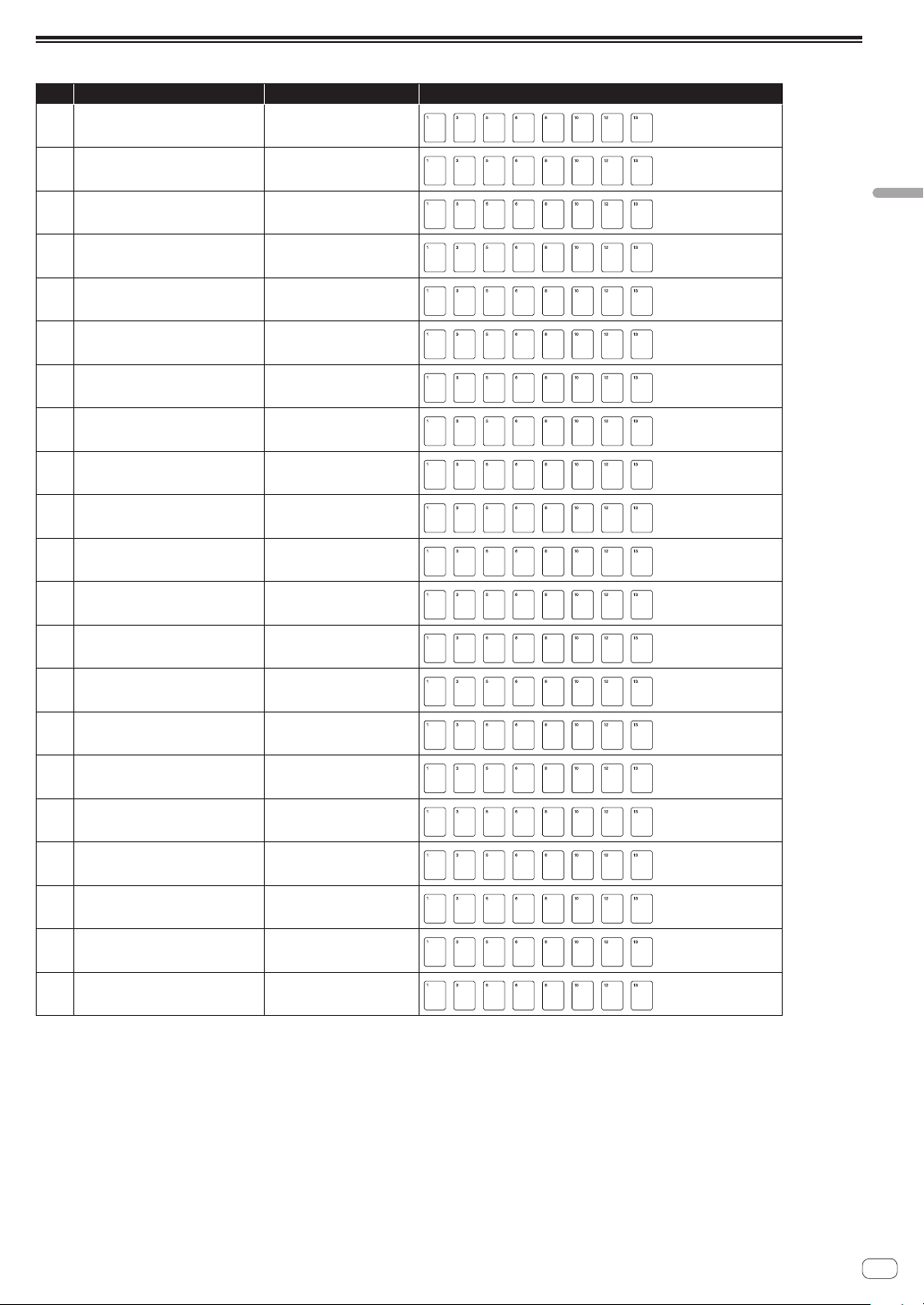
23
En
Changing the unit settings ([GLOBAL SETTING])
Keyboard mode scale list
No. Scale name Name in the display Keyboard assignment
1 Ionian Ionian
C
D F
G
CE
A B
2 Dorian Dorian
C
F
C
B
E
D G A
3 Phrygian Phrygian
C
F
G
C
Ab
D
B
E
4 Lydian Lydian
E
C
D F#
G
C
A B
5 Mixolydian Mixolydian
E
C
D F
G
C
A
B
6 Aeolian Aeolian
C
D F
G
C
Ab
B
E
7 Locrian Locrian
C
D
F
C
G
B
A
E
8 Major Pentatonic MajPenta
E
C
D G
A
E
C D
9 Minor Pentatonic MinPenta
F
C
G F
C
E
B
E
10 Whole tone Whole Tone
E
C
D F# D
C
G
#
A
#
11 Diminished Diminished
C
D F B
G#
A
E
G
12 Combination Diminished Combo Dim
C
F
G A
B
D
G
E
13 Altered Altered
C
E C
D#
D
F#
A
B
14 Major Blues Maj Blues
C
D E
G
D
A C
E
15 Minor Blues Min Blues
F
C
C
E
E
G
G
B
16 Raga Bhairav Raga B.
C
F
G
C
Ab
Db
E
B
17 Raga Gamanasrama Raga G.
C G C
D
E BF# A
18 Raga Todi Raga T.
C G C
D
BF#
E
A
19 Hawaiian Hawaiian
C A D
E
D G C
E
20 Ryukyu Ryukyu
C
D G
B
FF
C E
21 Japanese Miyakobushi JP Miyakob
C G F
D
F C
A
D
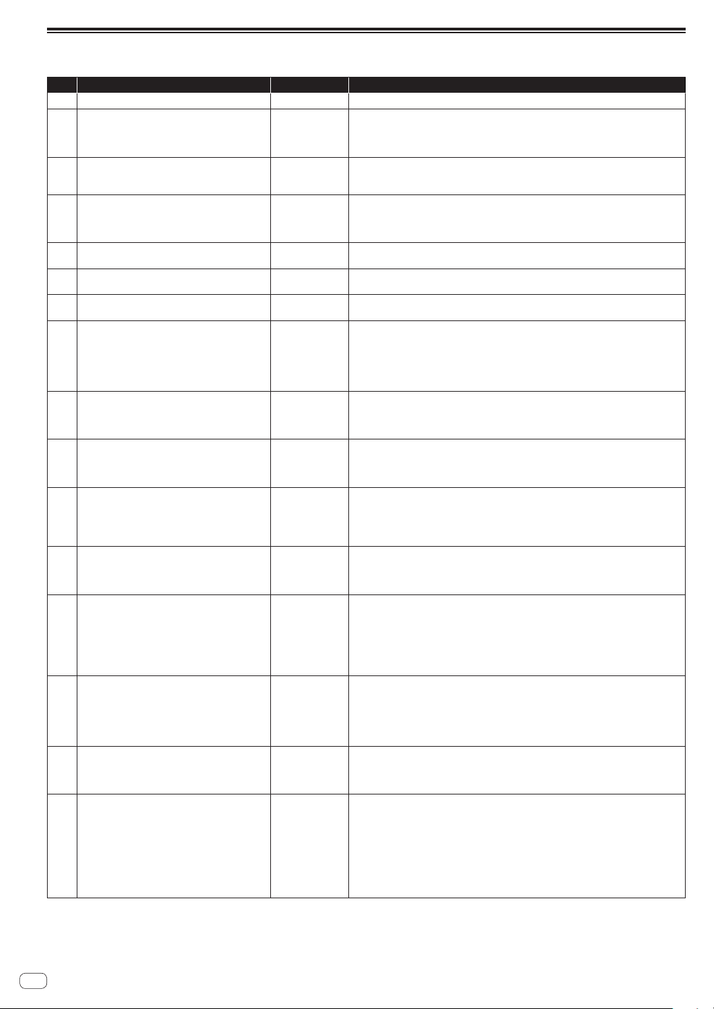
24
En
Alternate tuning list
No. Scale name Displayed Explanation
1 Equal Temperament
Equal Temperme..
The default Western tuning, based on the twelfth root of two.
2 Harmonic Series
HrmA1-60
MIDI notes 36-95 reflect harmonics 2 through 60 based on the fundamental of A= 27.5
Hz. The low C on a standard 5 octave keyboard acts as the root note (55 Hz), and the
harmonics play upwards from there. The remaining keys above and below the 5 octave
range are filled with the same intervals as Carlos’ Harmonic 12 Tone that follows.
3 Carlos Harmonic Twelve Tone
HrmA-12T
Wendy Carlos’ twelve note scale based on octave-repeating harmonics.
A= 1/1 (440 Hz).
1/1 17/16 9/8 19/16 5/4 21/16 11/8 3/2 13/8 27/16 7/4 15/8
4 Meantone Temperament
Meantone
An early tempered tuning, with better thirds than 12-ET. Sounds best in
the key of C. Use this to add an authentic touch to performances of early
Baroque music.
C=1/1 (260 Hz)
5 1/4 Tone Equal Temperament
1/4TonET
24 notes per octave, equally spaced 24root2 intervals. Mexican composer
Julian Carillo used this for custom-built pianos in the early 20th century.
6 19 Tone Equal Temperament
19ToneET
19 notes per octave (19root2) offering better thirds than 12-ET, a better
overall compromise if you can figure out the keyboard patterns.
7 31 Tone Equal Temperament
31ToneET
Many people consider 31root2 to offer the best compromise towards just intonation in an
equal temperament, but it can get very tricky to keep track of the intervals.
8 Pythagorean C
PythagoC
One of the earliest tuning systems known from history, the Pythagorean scale is
constructed from an upward series of pure fifths (3/2) transposed down into a single
octave. The tuning works well for monophonic melodies against fifth drones, but has a very
narrow palate of good chords to choose from.
C=1/1 (261.625 Hz)
1/1 256/243 9/8 32/27 81/64 4/3 729/512 3/2 128/81 27/16 16/9 243/128
9
Just Intonation in A with 7-limit Tritone
at D#
JIA7/5D
A rather vanilla 5-limit small interval JI, except for a single 7/5 tritone at D#, which offers
some nice possibilities for rotating around bluesy sevenths.
A=1/1 (440 Hz)
1/1 16/15 9/8 6/5 5/4 7/5 3/2 8/5 5/3 9/5 15/8
10 3-5 Lattice in A
3-5LattA
A pure 3 and 5-limit tuning which resolves to very symmetrical derived relationships
between notes.
A=1/1 (440 Hz)
1/1 16/15 10/9 6/5 5/4 4/3 64/45 3/2 8/5 5/3 16/9 15/8
11 3-7 Lattice in A
3-7LattA
A pure 3 and 7 -limit tuning which resolves to very symmetrical derived relationships
between notes. Some of the intervals are very close together, offering several choices for
the same nominal chords.
A= 1/1 (440 Hz)
1/1 9/8 8/7 7/6 9/7 21/16 4/3 3/2 32/21 12/7 7/4 63/32
12 Other Music 7-limit Black Keys in C
7LimBlkC
Created by the group Other Music for their homemade gamelan, this offers a wide range of
interesting chords and modes.
C=1/1 (261.625 Hz)
1/1 15/14 9/8 7/6 5/4 4/3 7/5 3/2 14/9 5/3 7/4 15/8
13 Dan Schmidt Pelog/Slendro
PelSlenB
Created for the Berkeley Gamelan group, this tuning fits an Indonesian-style heptatonic
Pelog on the white keys and pentatonic Slendro on the black keys, with B and BA acting as
1/1 for their respective modes. Note that some of the notes will have the same frequency.
By tuning the 1/1 to 60 Hz, Dan found a creative way to incorporate the inevitable line hum
into his scale.
BA, B = 1/1 (60 Hz)
1/1 1/1 9/8 7/6 5/4 4/3 11/8 3/2 3/2 7/4 7/4 15/8
14 Yamaha Just Major C
JlMajYam
When Yamaha decided to put preset microtunings into their FM synth product line, they
selected this and the following tuning as representative just intonations. As such, they
became the de-facto introduction to JI for many people. Just Major gives preferential
treatment to major thirds on the sharps, and a good fourth relative to the second.
C= 1/1 (261.625 Hz)
1/1 16/15 9/8 6/5 5/4 4/3 45/32 3/2 8/5 5/3 16/9 15/8
15 Yamaha Just Minor C
JlMinYam
Similar to Yamaha’s preset Just Major, the Just Minor gives preferential treatment to minor
thirds on the sharps, and has a good fifth relative to the second.
C= 1/1 (261.625 Hz)
1/1 25/24 10/9 6/5 5/4 4/3 45/32 3/2 8/5 5/3 16/9 15/8
16
Harry Partch 11-limit 43 Note Just
Intonation
Partch11
One of the pioneers of modern microtonal composition, Partch built a unique orchestra
with this tuning during the first half of the 20th century, to perform his own compositions.
The large number of intervals in this very dense scale offers a full vocabulary of expressive
chords and complex key changes. The narrow spacing also allows fixed-pitched
instruments like marimbas and organs to perform glissando-like passages.
G = 1/1 (392 Hz, MIDI note 67)
1/1 81/80 33/32 21/20 16/15 12/11 11/10 10/9 9/8 8/7 7/6 32/27 6/5 11/9 5/4
14/11 9/7 21/16 4/3 27/20 11/18 7/5 10/7 16/11 40/27 3/2 32/21 14/9 11/7 8/5
18/11 5/3 27/16 12/7 7/4 16/9 9/5 20/11 11/6 15/8 40/21 64/33 160/81
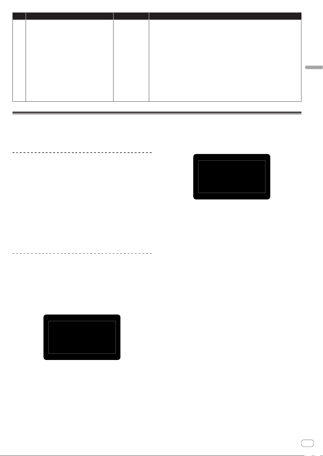
25
En
Changing the unit settings ([GLOBAL SETTING])
No. Scale name Displayed Explanation
17 Arabic 12-tone
ArabianC
A 12-tone approximation of an Arabic scale, which appears in some electronic keyboards
designed for use with Arabic music. Not a JI scale, nor equal tempered. These are the
intervals in Cents relative to C:
60 = Cents 0
61 = Cents + 151
62 = Cents + 204
63 = Cents + 294
64 = Cents + 355
65 = Cents + 498
66 = Cents + 649
67 = Cents + 702
68 = Cents + 853
69 = Cents + 906
70 = Cents + 996
71 = Cents + 1057
72 = Cents + 1200
Calibration
Although the TORAIZ AS-1 has been calibrated at the factory, it is necessary to calibrate the unit using its calibration function for stable operation to
adapt the unit to your usage environment. (Since the unit’s oscillators and filters are composed of analog circuits and operated by voltage control,
oscillation frequency and cutoff frequency may fluctuate due to the influence of external factors such as air temperature and power supply voltage.)
Calibration frequency
When using the TORAIZ AS-1 for the first time, it is recommended to
calibrate the unit using its calibration function after turning on the
power.
! Wait for about 10 to 20 minutes to warm up the unit after turning on
the power before you start calibrating.
! Repeat calibration continuously for several days in the environment
to be used so that you can tune the oscillators and filters to the
condition suitable for your environment.
It is also recommended to do the same when you intend to use the unit
in an environment different from usual, such as using it on stage.
! It is also recommended for your daily usage that you wait about 10
to 20 minutes after tuning on the power before you start using the
unit. This is to warm up the unit and reduce the variation factor of the
analog circuit due to the temperature rise inside the unit.
Performing calibration
1 Press the [GLOBAL/WRITE] button.
The [GLOBAL/WRITE] button lights up and the [GLOBAL SETTING]
screen appears in the display.
2 Turn the [PARAM/CATEGORY] control until the
[Calibrate] screen appears.
The [LATCH] button flashes.
24.
Press
Latch
to
0
Calib
ra
te
Calibrat
e
O
scs/Filt
3 Press the [Latch] button
Calibration starts.
When the calibration is completed, the display automatically returns to
the [Calibrate] screen shown in step 2.
! To cancel without performing the calibration, press the [GLOBAL/
WRITE] button again instead of the [LATCH] button. The display
returns to the main screen without calibration.
Screen example during calibration
OSC1...7
OSC2...7
0
Calibrating
DONE
LP
Filter...
3
HP
Resonance...1
4 Press the [GLOBAL/WRITE] button again.
The display returns to the main screen from the [GLOBAL SETTING]
screen.
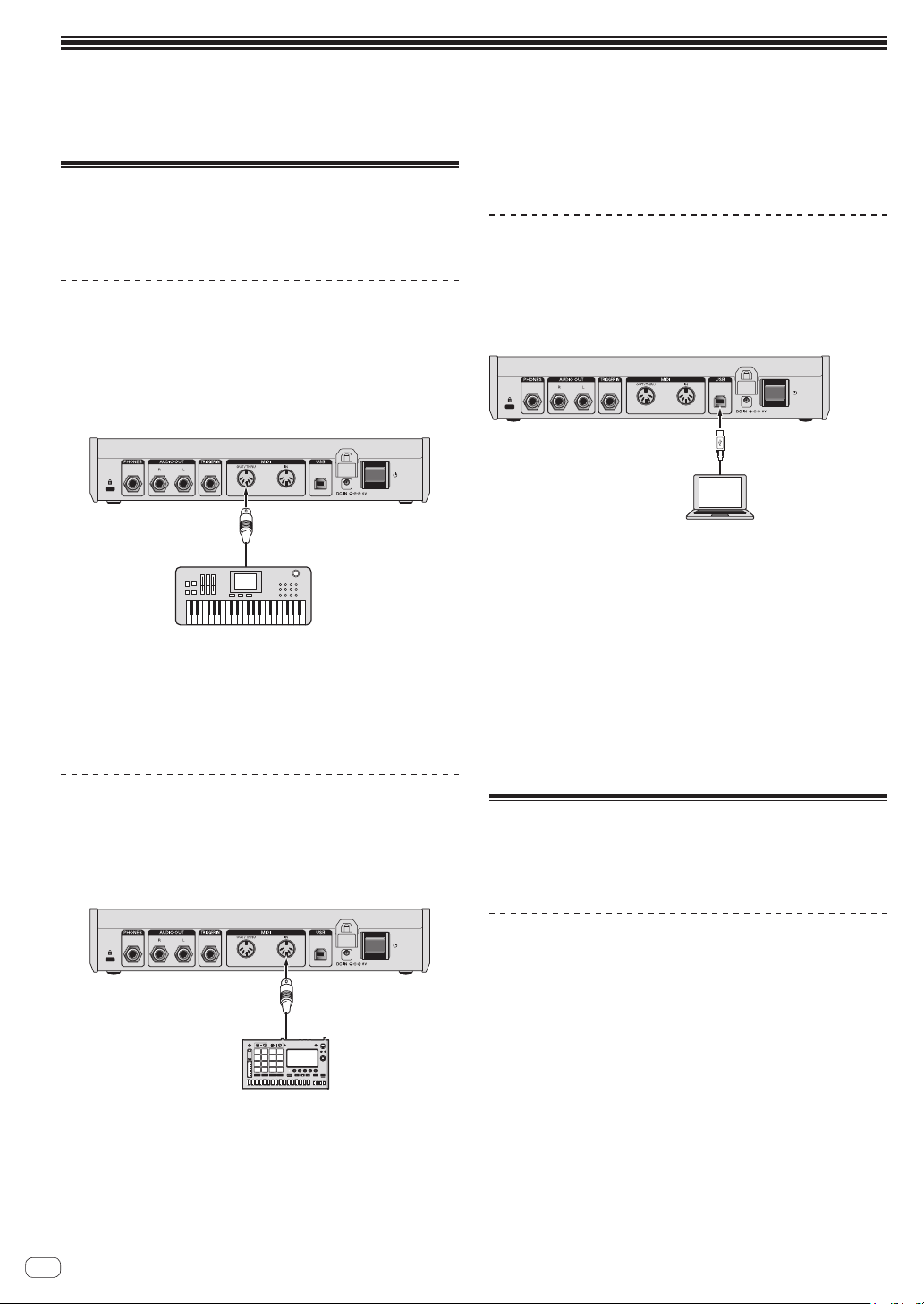
26
En
Using with external equipment
This chapter explains how to connect the TORAIZ AS-1 to an external MIDI device or computer and use it in combination with them.
For details on the setting items described in the operation procedures, see "Changing settings ([GLOBAL SETTING])" (page 22).
Connecting this unit to an external
MIDI device or computer and
playing
Playing an external MIDI device from this
unit
1 Connect the [MIDI OUT/THRU] of this unit to the
MIDI IN terminal of an external MIDI device with a
MIDI cable.
Synthesizer, sound
module, etc.
MIDI IN terminal
This unit
MIDI OUT/THRU
2 Set [MIDI Out Select] of [GLOBAL SETTING] to
[MIDI] or [MIDI + USB].
3 Play with the keyboard, sequencer or arpeggiator.
! To use the sequencer or arpeggiator, set [MIDI Seq/Arp Out] of
[GLOBAL SETTING] to [On].
Playing this unit from an external MIDI
device
1 Connect the [MIDI IN] of this unit to the MIDI OUT
terminal of an external MIDI device with a MIDI cable.
This unit
MIDI OUT terminal
MIDI IN
MIDI keyboard,
sequencer, etc.
2 Set [MIDI Control Enble] of [GLOBAL SETTING] to
[On].
3 Set [MIDI Channel] of [GLOBAL SETTING] to match
the MIDI channel output from the external MIDI
device.
4 Play with an external MIDI device.
Connecting this unit to a computer and
playing
1 Connect the [USB-B] terminal of this unit to a
computer with a USB cable.
Computer
USB-B terminal
This unit
USB terminal
2 Set [MIDI Control Enble] of [GLOBAL SETTING] to
[On].
3 Set [MIDI Out Select] of [GLOBAL SETTING] to
[USB] or [MIDI + USB].
4 Set [MIDI Channel] of [GLOBAL SETTING] to match
the MIDI channel output from a MIDI-compatible
application in the computer.
5 Play with the MIDI-compatible application in the
computer.
! When using the sequencer or arpeggiator of this unit, set [MIDI Seq/
Arp Out] of [GLOBAL SETTING] to [On].
Synchronizing and Playing this unit
with an external MIDI device or
computer
Synchronizing using this unit as a master
and an external MIDI device as a slave
1 Connect this unit to an external MIDI device or
computer.
! For the detailed connections and setting method, see “Connecting
this unit to an external MIDI device or computer and playing” above.
It is necessary to output MIDI signals from this unit.
2 Set [MIDI Clock Mode] of [GLOBAL SETTING] to
[Master].
3 Set [MIDI Clock Cable] of [GLOBAL SETTING] to the
connection cable you have used.
! When connecting with a MIDI cable, set to [MIDI Port] and when
connecting with a USB cable, set to [USB].
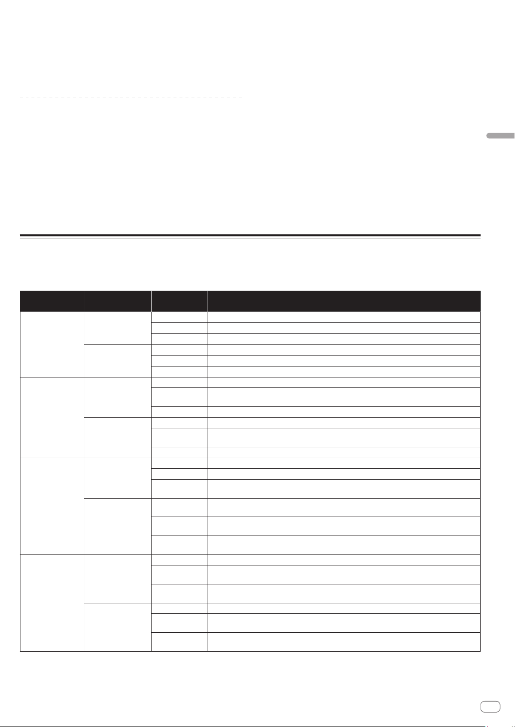
27
En
Using with external equipment
4 Play using the sequencer or arpeggiator of this
unit.
! The operations of play functions such as BPM and sequencer of the
external MIDI device or MIDI compatible application in the computer
synchronize with the BPM set on this unit.
! For the synchronizing settings of the external MIDI device, refer to
the operating instructions for the device.
Synchronizing using this unit as a slave
and an external MIDI device as a master
1 Connect this unit to an external MIDI device or
computer.
! For the detailed connections and setting method, see “Connecting
this unit to an external MIDI device or computer and playing” (page
26). It is necessary to output MIDI signals from the external MIDI
device.
2 Set [MIDI Clock Mode] of [GLOBAL SETTING] to
[Slave], [Slave Thru] or [Slave No S/S].
! For the details for how each setting works, see “Changing the unit
settings ([GLOBAL SETTING])” (page 21).
! If this unit is set as a slave, the [CLOCK TAP] button turns off.
While this unit is receiving the external MIDI Timing Clock, the
[CLOCK TAP] button flashes synchronizing with the MIDI Timing
Clock.
3 Set [MIDI Clock Cable] of [GLOBAL SETTING] to the
connection cable you have used.
! When connecting with a MIDI cable, set to [MIDI Port] and when
connecting with a USB cable, set to [USB].
4 Play using the sequencer or arpeggiator of the
external MIDI device or MIDI-compatible application
in the computer.
! The operations of play functions such as BPM and sequencer of this
unit synchronize with the BPM set on the external MIDI device or
MIDI compatible application in the computer.
! For the synchronizing settings of the external MIDI device, refer to
the manual of the device.
Using the [TRIGGER IN] of this unit to control the play functions of this unit
By connecting a foot pedal or a device that sends an audio signal which works as a trigger signal to the [TRIGGER IN] of this unit, you can control the
play functions of this unit such as sequencer, arpeggiator and the others. This offers you a variety of performance options.
There are four modes to control the play functions of this unit by [TRIGGER IN] input. The mode can be set in [Seq Jack Mode] of [GLOBAL SETTING].
Seq Jack Mode Connected device
(input signal)
Play function Behavior
Pedal
Foot switch
Sequencer Plays/stops the sequence.
Arpeggiator This does not affect the operation.
Keyboard
This does not affect the operation.
Audio signal
(trigger signal)
Sequencer Plays/stops the sequence.
Arpeggiator This does not affect the operation.
Keyboard This does not affect the operation.
Trigger
Foot switch
Sequencer When the sequencer is On, advances one step each time you step on the foot switch.
Arpeggiator
When the arpeggiator is On, plays each sound of the held notes each time you step on the foot switch
according to the arpeggiator setting.
Keyboard This does not affect the operation.
Audio signal
(trigger signal)
Sequencer When the sequencer is On, advances one step each time an audio signal is input.
Arpeggiator
When the arpeggiator is On, plays each sound of the held notes each time an audio signal is input
according to the arpeggiator setting.
Keyboard This does not affect the operation.
Gate
Foot switch
Sequencer When the sequencer is On, plays the sequence while you are stepping on the foot switch.
Arpeggiator When the arpeggiator is On, the held notes are arpeggiated while you are stepping on the foot switch.
Keyboard
The held notes are played when you step on the foot switch. The notes are played continuously
(note-on state continues) if you keep stepping on the foot switch.
Audio signal
(trigger signal)
Sequencer
When the sequencer is On, plays the sequence while an audio signal is input. The sequence plays
continuously when inputting a continuous sound.
Arpeggiator
When the arpeggiator is On, the held notes are arpeggiated while an audio signal is input. The
arpeggio plays continuously when inputting a continuous sound.
Keyboard
The held notes are played when an audio signal is input. The notes are played continuously (note-on
state continues) while a continuous sound is input.
Gate+Trigger
Foot switch
Sequencer When the sequencer is On, advances one step each time you step on the foot switch.
Arpeggiator
When the arpeggiator is On, plays each sound of the held notes each time you step on the foot switch
depending on the arpeggiator setting.
Keyboard
The held notes are played when you step on the foot switch. The notes are played continuously
(note-on state continues) if you keep stepping on the foot switch.
Audio signal
(trigger signal)
Sequencer When the sequencer is On, advances one step each time an audio signal is input.
Arpeggiator
When the arpeggiator is On, plays each sound of the held notes each time an audio signal is input
depending on the arpeggiator setting.
Keyboard
The held notes are played when an audio signal is input. The notes are played continuously (note-on
state continues) while a continuous sound is input.
! Depending on the polarity of the foot pedal used, it may not operate correctly. If necessary, change the setting of [Pedal Polarity] of [GLOBAL
SETTING].
! When using an audio signal as a trigger signal, input a sound with sharp attack and decay like a pulse signal or click sound with a sufficiently high
volume.
28
En
MIDI implementation
This unit sends and receives MIDI data according to the settings selected in the [GLOBAL SETTING] menu.
Check the following list to confirm the types of MIDI data that can be sent and received.
MIDI Messages
System Real Time Messages
Status Explanation
0b1111 1000 MIDI Timing Clock
Received Channel Messages
Status
1st Data Byte 2nd Data Byte 3rd Data Byte
Description
1000 nnnn 0kkkkkkk 0vvvvvvv Note Off. Velocity is ignored.
1001 nnnn 0kkkkkkk 0vvvvvvv Note On. Note off if vvvvvvv = 0.
1011 nnnn 0vvvvvvv 0vvvvvvv Control Change
1100 nnnn 0vvvvvvv Program Change, 0-98 for programs 1-99 within current bank
1101 nnnn 0vvvvvvv Channel Pressure
1110 nnnn 0vvvvvvv 0vvvvvvv
Pitch Bend
LS Byte (LSB) then MS Byte (MSB)
Where:
0kkkkkkk = Note Number 0-127
nnnn =
Channel Number 0 to 15 (MIDI channel 1 to 16)
! Ignored if MIDI channel set to ALL.
0vvvvvvv = Value
Received Controller Messages
Status
1st Data Byte 2nd Data Byte 3rd Data Byte
Description
1011 nnnn 0000 0001 0vvvvvvv Mod Wheel: directly assignable controller
1011 nnnn 0000 0100 0vvvvvvv Foot Controller: directly assignable controller
1011 nnnn 0000 0111 0vvvvvvv Volume: Combined with Master Volume and Voice Volume
1011 nnnn 0100 1010 0vvvvvvv Brightness: Added to low-pass filter cutoff frequency
1011 nnnn 0010 0000 0vvvvvvv Bank Select: 0 - 5 select user banks 1 - 5; 6 - 10 select factory banks 1 - 5; others ignored
1011 nnnn 0100 0000 0vvvvvvv Damper pedal: Holds envelopes in Sustain if 0100 0000 or higher
1011 nnnn 0111 1011 0vvvvvvv All Notes Off: Clear all MIDI notes
1011 nnnn 0111 1001 0vvvvvvv Reset All Controllers: Clears all MIDI controllers to 0, MIDI volume to maximum
Refer also to “MIDI Continuous Controllers (CC) Transmitted/Received” (page 33) and “Received NRPN Message Format” (page 29).
29
En
MIDI Implementation
Transmitted Channel Messages
Status
1st Data Byte 2nd Data Byte 3rd Data Byte
Description
1000 nnnn 0kkkkkkk 0 Note Off
1001 nnnn 0kkkkkkk 0vvvvvvv Note On
1011 nnnn 0vvvvvvv 0vvvvvvv Control Change; see "Transmitted Controller Messages" below.
1100 nnnn 0vvvvvvv Program Change, 0-98 for programs 1-99 within current bank
Where:
0kkkkkkk = Note Number 0-127
nnnn = Channel Number 0 to 15 (MIDI channel 1 to 16)
! Ignored if MIDI channel set to ALL.
0vvvvvvv = Value
Transmitted Controller Messages
Status
1st Data Byte 2nd Data Byte 3rd Data Byte
Description
1011 nnnn 0010 0000 0vvvvvvv Bank Select: 0-9 for banks 1-10
1011 nnnn 0000 0111 0vvvvvvv [VOLUME] control (knob)
Refer also to “MIDI Continuous Controllers (CC) Transmitted/Received” (page 33) and “Transmitted NRPN Message Format” below.
NRPN (Non-Registered Parameter Number) Messages
Transmitted NRPN Message Format
Status Description
1011 nnnn Control Change
011 0011 NRPN parameter number MSB CC
0vvv vvvv Parameter Number MSB
0110 0010 NRPN parameter number LSB CC
0vvv vvvv Parameter Number LSB
0000 0010 NRPN parameter value MSB CC
0vvv vvvv Parameter Value MSB
0010 0110 NRPN parameter value LSB CC
0vvv vvvv Parameter Value LSB
Received NRPN Message Format
Status
1st Data Byte 2nd Data Byte 3rd Data Byte
Description
1011 nnnn 0110 0011 0vvvvvvv NRPN parameter number MSB CC
1011 nnnn 0110 0010 0vvvvvvv NRPN parameter number LSB CC
1011 nnnn 0000 0110 0vvvvvvv NRPN parameter value MSB CC
1011 nnnn 0010 0110 0vvvvvvv NRPN parameter value LSB CC
1011 nnnn 0110 0000 NRPN parameter value increment
1011 nnnn 0110 0001 NRPN parameter value decrement
1011 nnnn 0010 0101 1111111
RPN parameter number MSB CC - Reset NRPN parameter number (when both MSB and LSB
received)
1011 nnnn 0010 0100 1111111
RPN parameter number LSB CC - Reset NRPN parameter number (when both MSB and LSB
received)
30
En
Sysex Messages
Universal SysEx Device Inquiry
Status Description
1111 0000 System Exclusive (SysEx)
0111 1110 Non-realtime message
0vvv vvvv
If MIDI channel is set to 1-16, 0vvv vvvv must match (unless MIDI channel = ALL); always responds
If 0vvv vvvv = 0111 1111
0000 0110 Inquiry message
0000 0001 Inquiry Request
1111 0111 End of exclusive (EOX)
The Toraiz AS-1 responds with:
Status Description
1111 0000 System Exclusive (SysEx)
0111 1110 Non-realtime message
0vvv vvvv If MIDI channel = ALL, ovvv vvvv = 0111 1111. Otherwise 0vvv vvvv = Channel number 0-15
0000 0110 Inquiry message
0000 0010 Inquiry Reply
0000 0000 Pioneer DJ ID (first byte)
0100 0000 Pioneer DJ ID (second byte)
0000 0101 Pioneer DJ ID (third byte)
0000 0000 Toraiz ID (first byte)
0000 0000 Toraiz ID (second byte)
0000 0001 Toraiz ID (third byte)
0000 1000 Toraiz ID (fourth byte)
0001 0000 Device ID
0jjj nnnn
Main Software version
jjj - Minor rev; nnnn - Major rev
1111 0111 End of exclusive (EOX)
The Toraiz AS-1 will send out the program data in the format described in “Program Data Dump” (page 31).
Request Program Dump
Status Description
1111 0000
System Exclusive (SysEx)
0000 0000
Pioneer DJ ID (first byte)
0100 0000
Pioneer DJ ID (second byte)
0000 0101
Pioneer DJ ID (third byte)
0000 0000
Toraiz ID (first byte)
0000 0000
Toraiz ID (second byte)
0000 0001
Toraiz ID (third byte)
0000 1000
Toraiz ID (fourth byte)
0001 0000
Device ID
0000 0101
Request program transmit
0000 vvvv
Bank Number, 0-9
0vvv vvvv
Program Number, 0-99
1111 0111
End of exclusive (EOX)
The Toraiz AS-1 will send out the current program edit buffer in the format described in “Program Edit Buffer Data Dump” (page 32).
31
En
MIDI Implementation
Request Program Edit Buffer Dump
Status Description
1111 0000 System Exclusive (SysEx)
0000 0000 Pioneer DJ ID (first byte)
0100 0000 Pioneer DJ ID (second byte)
0000 0101 Pioneer DJ ID (third byte)
0000 0000 Toraiz ID (first byte)
0000 0000 Toraiz ID (second byte)
0000 0001 Toraiz ID (third byte)
0000 1000 Toraiz ID (fourth byte)
0001 0000 Device ID
0000 0110 Request program edit buffer transmit
1111 0111 End of exclusive (EOX)
The Toraiz AS-1 will send out the current values of Global Parameters in the format described in “Global Parameters Data Dump” (page 32).
Request Global Parameter Dump
Status Description
1111 0000 System Exclusive (SysEx)
0000 0000 Pioneer DJ ID (first byte)
0100 0000 Pioneer DJ ID (second byte)
0000 0101 Pioneer DJ ID (third byte)
0000 0000 Toraiz ID (first byte)
0000 0000 Toraiz ID (second byte)
0000 0001 Toraiz ID (third byte)
0000 1000 Toraiz ID (fourth byte)
0001 0000 Device ID
0000 1110 Request global parameter transmit
1111 0111 End of exclusive (EOX)
Program Data Dump
Status Description
1111 0000 System Exclusive (SysEx)
0000 0000 Pioneer DJ ID (first byte)
0100 0000 Pioneer DJ ID (second byte)
0000 0101 Pioneer DJ ID (third byte)
0000 0000 Toraiz ID (first byte)
0000 0000 Toraiz ID (second byte)
0000 0001 Toraiz ID (third byte)
0000 1000 Toraiz ID (fourth byte)
0001 0000 Device ID
0000 0010 Program Data
0000 vvvv Bank number 0-9
0vvv vvvv Program number 0-99
0vvv vvvv 1024 bytes expanded to 1171 MIDI bytes in "packed MS bit" format.
1111 0111 End of exclusive (EOX)
32
En
Program Edit Buffer Data Dump
Status Description
1111 0000 System Exclusive (SysEx)
0000 0000 Pioneer DJ ID (first byte)
0100 0000 Pioneer DJ ID (second byte)
0000 0101 Pioneer DJ ID (third byte)
0000 0000 Toraiz ID (first byte)
0000 0000 Toraiz ID (second byte)
0000 0001 Toraiz ID (third byte)
0000 1000 Toraiz ID (fourth byte)
0001 0000 Device ID
0000 0011 Edit Buffer Data
0vvv vvvv 1024 bytes expanded to 1171 MIDI bytes in "packed MS bit" format.
1111 0111 End of exclusive (EOX)
Global Parameters Data Dump
Status Description
1111 0000 System Exclusive (SysEx)
0000 0000 Pioneer DJ ID (first byte)
0100 0000 Pioneer DJ ID (second byte)
0000 0101 Pioneer DJ ID (third byte)
0000 0000 Toraiz ID (first byte)
0000 0000 Toraiz ID (second byte)
0000 0001 Toraiz ID (third byte)
0000 1000 Toraiz ID (fourth byte)
0001 0000 Device ID
0000 1111 Global parameter data
0vvv vvvv 54 nibbles (LSB then MSB) for 27 Global parameters
1111 0111 End of exclusive (EOX)
33
En
MIDI Implementation
MIDI Continuous Controllers (CC)
Transmitted/Received
This unit's [GLOBAL SETTING] and MIDI Continuous Controllers (CC)
are related as follows.
! When [MIDI Param Send] is set to [CC], this unit transmits CC.
! When [MIDI Param Rcv] is set to [CC], this unit recognizes CC and
receives from CC.
The following table details how MIDI Continuous Controllers (CC) are
mapped to this unit's controls.
CC Parameter
3 V_BPM,
5 V_GLIDE_MODE,
8 V_OSC_1_SUB_LEVEL,
39 V_VOICE_VOLUME,
40 V_ENV_VCA_AMT,
41 V_ENV_VCA_VEL_ON_OFF,
43 V_ENV_VCA_ATT,
44 V_ENV_VCA_DEC,
45 V_ENV_VCA_SUS,
46 V_ENV_VCA_REL,
47 V_ENV_LOWPASS_AMT,
50 V_ENV_FILTER_ATT,
51 V_ENV_FILTER_DEC,
52 V_ENV_FILTER_SUS,
53 V_ENV_FILTER_REL,
54 V_ENV_HIGHPASS_AMT,
58 M_ARP_ON_OFF,
59 M_ARP_MODE,
60 M_ARP_RANGE,
62 M_ARP_TIME_SIG,
65 V_GLIDE_ON_OFF,
67 V_OSC_1_FREQ,
69 V_OSC_1_LEVEL,
70 V_OSC_1_SHAPE,
71 V_OSC_1_PULSE_WIDTH,
75 V_OSC_2_FREQ,
76 V_OSC_2_FREQ_FINE,
77 V_OSC_2_LEVEL,
78 V_OSC_2_SHAPE,
79 V_OSC_2_PULSE_WIDTH,
102 V_LOWPASS_FREQ,
103 V_LOWPASS_RESONANCE,
104 V_LOWPASS_KEY_AMT,
105 V_LOWPASS_VEL_ON,
106 V_HIGHPASS_FREQ,
107 V_HIGHPASS_RESONANCE,
108 V_HIGHPASS_KEY_AMT,
109 V_HIGHPASS_VEL_ON,
Program Parameter Data
The following table lists Toraiz AS-1's program parameters.
NRPN Value Parameter
0 0-60 V_OSC_1_FREQ,
1 0-1 V_OSC_1_SYNC,
2 0-127 V_OSC_1_LEVEL,
3 0-254 V_OSC_1_SHAPE,
4 0-255 V_OSC_1_PULSE_WIDTH,
5 0-60 V_OSC_2_FREQ,
6 0-254 V_OSC_2_FREQ_FINE,
7 0-127 V_OSC_2_LEVEL,
8 0-254 V_OSC_2_SHAPE,
9 0-255 V_OSC_2_PULSE_WIDTH,
10 0-1 V_OSC_2_LOW_FREQ,
11 0-1 V_OSC_2_KEY_ON_OFF,
27 0-127 V_OSC_1_SUB_LEVEL,
28 0-3 V_GLIDE_MODE,
29 0-1 V_GLIDE_ON_OFF,
30 0-127 V_GLIDE_RATE,
31 0-12 V_PBEND_RANGE,
32 0-127 V_NOISE_LEVEL,
33 0-127 V_SLOP,
45 0-164 V_LOWPASS_FREQ,
46 0-255 V_LOWPASS_RESONANCE,
47 0-2 V_LOWPASS_KEY_AMT,
48 0-1 V_LOWPASS_VEL_ON,
49 0-127 V_HIGHPASS_FREQ,
50 0-255 V_HIGHPASS_RESONANCE,
51 0-2 V_HIGHPASS_KEY_AMT,
52 0-1 V_HIGHPASS_VEL_ON,
62 0-127 V_VOICE_VOLUME,
66 0-127 V_ENV_VCA_AMT,
67 0-127 V_ENV_VCA_ATT,
68 0-127 V_ENV_VCA_DEC,
69 0-127 V_ENV_VCA_SUS,
70 0-127 V_ENV_VCA_REL,
71 0-1 V_ENV_VCA_VEL_ON_OFF,
77 0-254 V_ENV_LOWPASS_AMT,
78 0-127 V_ENV_FILTER_ATT,
79 0-127 V_ENV_FILTER_DEC,
80 0-127 V_ENV_FILTER_SUS,
81 0-127 V_ENV_FILTER_REL,
82 0-127 V_ENV_HIGHPASS_AMT,
88 0-255 V_LFO_FREQ,
89 0-255 V_LFO_INITIAL_AMT,
90 0-4 V_LFO_SHAPE,
91 0-1 V_LFO_EXT_SYNC,
93 0-1 V_LFO_FREQ_1_DEST_ON_OFF,
94 0-1 V_LFO_FREQ_2_DEST_ON_OFF,
95 0-1 V_LFO_PW_1_2_DEST_ON_OFF,
96 0-1 V_LFO_AMP_DEST_ON_OFF,
97 0-1 V_LFO_LOWPASS_DEST_ON_OFF,
98 0-1 V_LFO_HIGHPASS_DEST_ON_OFF,
109 0-254 V_PRESSURE_AMT,
110 0-1 V_PRESSURE_FREQ_1_DEST_ON_OFF,
111 0-1 V_PRESSURE_FREQ_2_DEST_ON_OFF,
112 0-1 V_PRESSURE_LOWPASS_DEST_ON_OFF,
113 0-1 V_PRESSURE_HIGHPASS_DEST_ON_OFF,
114 0-1 V_PRESSURE_VCA_DEST_ON_OFF,
115 0-1 V_PRESSURE_LFO_AMT_DEST_ON_OFF,
34
En
NRPN Value Parameter
119 0-3 V_FX_1_SELECT,
120 0-127 V_FX_1_MIX,
121 0-255 V_FX_1_PARAM_1,
122 0-127 V_FX_1_PARAM_2,
123 0-1 V_FX_1_SYNC,
124 0-10 V_FX_1_SYNC_RATE,
127 0-4 V_FX_2_SELECT,
128 0-127 V_FX_2_MIX,
129 0-127 V_FX_2_PARAM_1,
130 0-127 V_FX_2_PARAM_2,
135 0-1 V_FX_ON_OFF,
143 0-254 V_POLYMOD_FILTER_ENV_AMT,
144 0-254 V_POLYMOD_OSC_2_AMT,
145 0-1 V_POLYMOD_FREQ_1_DEST_ON_OFF,
146 0-1 V_POLYMOD_SHAPE_1_DEST_ON_OFF,
147 0-1 V_POLYMOD_PW_1_DEST_ON_OFF,
148 0-1 V_POLYMOD_LOWPASS_DEST_ON_OFF,
149 0-1 V_POLYMOD_HIGHPASS_DEST_ON_OFF,
158 0-5 V_KEY_MODE,
160 0-1 M_ARP_ON_OFF,
161 0-4 M_ARP_MODE,
162 0-2 M_ARP_RANGE,
163 0-9 M_ARP_TIME_SIG,
167 30-250 V_BPM,
168 0-1 M_SEQ_ON_OFF,
170 0-6 M_SEQ_LENGTH,
172 0-1 M_SEQ_RECORD_ON_OFF,
180 0-254 V_SLIDER_OSC_FREQ_1_AMT;
181 0-254 V_SLIDER_OSC_FREQ_2_AMT;
182 0-254 V_SLIDER_LFO_AMT;
183 0-254 V_SLIDER_FX_1_MIX_AMT;
184 0-254 V_SLIDER_FX_2_MIX_AMT;
185 0-254 V_SLIDER_LPF_AMT;
186 0-254 V_SLIDER_HPF_AMT;
256 12-108 M_SEQ_STEP_1_NOTE_1,
257 12-108 M_SEQ_STEP_2_NOTE_1,
258 12-108 M_SEQ_STEP_3_NOTE_1,
259 12-108 M_SEQ_STEP_4_NOTE_1,
260 12-108 M_SEQ_STEP_5_NOTE_1,
261 12-108 M_SEQ_STEP_6_NOTE_1,
262 12-108 M_SEQ_STEP_7_NOTE_1,
263 12-108 M_SEQ_STEP_8_NOTE_1,
264 12-108 M_SEQ_STEP_9_NOTE_1,
265 12-108 M_SEQ_STEP_10_NOTE_1,
266 12-108 M_SEQ_STEP_11_NOTE_1,
267 12-108 M_SEQ_STEP_12_NOTE_1,
268 12-108 M_SEQ_STEP_13_NOTE_1,
269 12-108 M_SEQ_STEP_14_NOTE_1,
270 12-108 M_SEQ_STEP_15_NOTE_1,
271 12-108 M_SEQ_STEP_16_NOTE_1,
272 12-108 M_SEQ_STEP_17_NOTE_1,
273 12-108 M_SEQ_STEP_18_NOTE_1,
274 12-108 M_SEQ_STEP_19_NOTE_1,
275 12-108 M_SEQ_STEP_20_NOTE_1,
276 12-108 M_SEQ_STEP_21_NOTE_1,
277 12-108 M_SEQ_STEP_22_NOTE_1,
278 12-108 M_SEQ_STEP_23_NOTE_1,
279 12-108 M_SEQ_STEP_24_NOTE_1,
280 12-108 M_SEQ_STEP_25_NOTE_1,
281 12-108 M_SEQ_STEP_26_NOTE_1,
282 12-108 M_SEQ_STEP_27_NOTE_1,
NRPN Value Parameter
283 12-108 M_SEQ_STEP_28_NOTE_1,
284 12-108 M_SEQ_STEP_29_NOTE_1,
285 12-108 M_SEQ_STEP_30_NOTE_1,
286 12-108 M_SEQ_STEP_31_NOTE_1,
287 12-108 M_SEQ_STEP_32_NOTE_1,
288 12-108 M_SEQ_STEP_33_NOTE_1,
289 12-108 M_SEQ_STEP_34_NOTE_1,
290 12-108 M_SEQ_STEP_35_NOTE_1,
291 12-108 M_SEQ_STEP_36_NOTE_1,
292 12-108 M_SEQ_STEP_37_NOTE_1,
293 12-108 M_SEQ_STEP_38_NOTE_1,
294 12-108 M_SEQ_STEP_39_NOTE_1,
295 12-108 M_SEQ_STEP_40_NOTE_1,
296 12-108 M_SEQ_STEP_41_NOTE_1,
297 12-108 M_SEQ_STEP_42_NOTE_1,
298 12-108 M_SEQ_STEP_43_NOTE_1,
299 12-108 M_SEQ_STEP_44_NOTE_1,
300 12-108 M_SEQ_STEP_45_NOTE_1,
301 12-108 M_SEQ_STEP_46_NOTE_1,
302 12-108 M_SEQ_STEP_47_NOTE_1,
303 12-108 M_SEQ_STEP_48_NOTE_1,
304 12-108 M_SEQ_STEP_49_NOTE_1,
305 12-108 M_SEQ_STEP_50_NOTE_1,
306 12-108 M_SEQ_STEP_51_NOTE_1,
307 12-108 M_SEQ_STEP_52_NOTE_1,
308 12-108 M_SEQ_STEP_53_NOTE_1,
309 12-108 M_SEQ_STEP_54_NOTE_1,
310 12-108 M_SEQ_STEP_55_NOTE_1,
311 12-108 M_SEQ_STEP_56_NOTE_1,
312 12-108 M_SEQ_STEP_57_NOTE_1,
313 12-108 M_SEQ_STEP_58_NOTE_1,
314 12-108 M_SEQ_STEP_59_NOTE_1,
315 12-108 M_SEQ_STEP_60_NOTE_1,
316 12-108 M_SEQ_STEP_61_NOTE_1,
317 12-108 M_SEQ_STEP_62_NOTE_1,
318 12-108 M_SEQ_STEP_63_NOTE_1,
319 12-108 M_SEQ_STEP_64_NOTE_1,
320 0-127 M_SEQ_STEP_1_VEL_1,
321 0-127 M_SEQ_STEP_2_VEL_1,
322 0-127 M_SEQ_STEP_3_VEL_1,
323 0-127 M_SEQ_STEP_4_VEL_1,
324 0-127 M_SEQ_STEP_5_VEL_1,
325 0-127 M_SEQ_STEP_6_VEL_1,
326 0-127 M_SEQ_STEP_7_VEL_1,
327 0-127 M_SEQ_STEP_8_VEL_1,
328 0-127 M_SEQ_STEP_9_VEL_1,
329 0-127 M_SEQ_STEP_10_VEL_1,
330 0-127 M_SEQ_STEP_11_VEL_1,
331 0-127 M_SEQ_STEP_12_VEL_1,
332 0-127 M_SEQ_STEP_13_VEL_1,
333 0-127 M_SEQ_STEP_14_VEL_1,
334 0-127 M_SEQ_STEP_15_VEL_1,
335 0-127 M_SEQ_STEP_16_VEL_1,
336 0-127 M_SEQ_STEP_17_VEL_1,
337 0-127 M_SEQ_STEP_18_VEL_1,
338 0-127 M_SEQ_STEP_19_VEL_1,
339 0-127 M_SEQ_STEP_20_VEL_1,
340 0-127 M_SEQ_STEP_21_VEL_1,
341 0-127 M_SEQ_STEP_22_VEL_1,
342 0-127 M_SEQ_STEP_23_VEL_1,
343 0-127 M_SEQ_STEP_24_VEL_1,

35
En
MIDI Implementation
NRPN Value Parameter
344 0-127 M_SEQ_STEP_25_VEL_1,
345 0-127 M_SEQ_STEP_26_VEL_1,
346 0-127 M_SEQ_STEP_27_VEL_1,
347 0-127 M_SEQ_STEP_28_VEL_1,
348 0-127 M_SEQ_STEP_29_VEL_1,
349 0-127 M_SEQ_STEP_30_VEL_1,
350 0-127 M_SEQ_STEP_31_VEL_1,
351 0-127 M_SEQ_STEP_32_VEL_1,
352 0-127 M_SEQ_STEP_33_VEL_1,
353 0-127 M_SEQ_STEP_34_VEL_1,
354 0-127 M_SEQ_STEP_35_VEL_1,
355 0-127 M_SEQ_STEP_36_VEL_1,
356 0-127 M_SEQ_STEP_37_VEL_1,
357 0-127 M_SEQ_STEP_38_VEL_1,
358 0-127 M_SEQ_STEP_39_VEL_1,
359 0-127 M_SEQ_STEP_40_VEL_1,
360 0-127 M_SEQ_STEP_41_VEL_1,
361 0-127 M_SEQ_STEP_42_VEL_1,
362 0-127 M_SEQ_STEP_43_VEL_1,
363 0-127 M_SEQ_STEP_44_VEL_1,
364 0-127 M_SEQ_STEP_45_VEL_1,
365 0-127 M_SEQ_STEP_46_VEL_1,
366 0-127 M_SEQ_STEP_47_VEL_1,
367 0-127 M_SEQ_STEP_48_VEL_1,
368 0-127 M_SEQ_STEP_49_VEL_1,
369 0-127 M_SEQ_STEP_50_VEL_1,
370 0-127 M_SEQ_STEP_51_VEL_1,
371 0-127 M_SEQ_STEP_52_VEL_1,
372 0-127 M_SEQ_STEP_53_VEL_1,
373 0-127 M_SEQ_STEP_54_VEL_1,
374 0-127 M_SEQ_STEP_55_VEL_1,
375 0-127 M_SEQ_STEP_56_VEL_1,
376 0-127 M_SEQ_STEP_57_VEL_1,
377 0-127 M_SEQ_STEP_58_VEL_1,
378 0-127 M_SEQ_STEP_59_VEL_1,
379 0-127 M_SEQ_STEP_60_VEL_1,
380 0-127 M_SEQ_STEP_61_VEL_1,
381 0-127 M_SEQ_STEP_62_VEL_1,
382 0-127 M_SEQ_STEP_63_VEL_1,
383 0-127 M_SEQ_STEP_64_VEL_1,
1024 0-100 V_GLOBAL_MASTER_FINE;
1025 0-24 V_GLOBAL_MASTER_COARSE;
1026 0-16 V_GLOBAL_MIDI_CHANNEL;
1027 0-4 V_GLOBAL_MIDI_CLOCK_MODE;
1028 0-1 V_GLOBAL_MIDI_CLOCK_CABLE;
1029 0-2 V_GLOBAL_MIDI_PARAM_SEND;
1030 0-2 V_GLOBAL_MIDI_PARAM_RCV;
1031 0-1 V_GLOBAL_MIDI_CONTROL_ENABLE;
1032 0-1 V_GLOBAL_MIDI_SYSEX_CABLE;
1033 0-2 V_GLOBAL_MIDI_OUT_SELECT;
1034 0-1 V_GLOBAL_MIDI_OUT_THRU;
1035 0-1 V_GLOBAL_LOCAL_CONTROL:
1037 0-2 V_GLOBAL_POT_MODE;
1041 0-3 V_GLOBAL_SEQ_JACK_MODE;
1042 0-1 V_GLOBAL_PEDAL_POLARITY;
1043 0-1 V_GLOBAL_MONO_STEREO;
1044 0-16 V_GLOBAL_ALTERNATE_TUNING;
1045 0-21 V_GLOBAL_SCALE_MODE;
1046 0-1 V_GLOBAL_MIDI_SEQ_OUT;
1047 0-1 V_GLOBAL_SCREEN_SAVER;
1049 0-9 V_GLOBAL_KEY_SENSITIVITY;
NRPN Value Parameter
1050 0-99 V_GLOBAL_QUICK_PROGRAM_1_PRGM_SELECT;
1051 0-99 V_GLOBAL_QUICK_PROGRAM_2_PRGM_SELECT;
1052 0-99 V_GLOBAL_QUICK_PROGRAM_3_PRGM_SELECT;
1053 0-99 V_GLOBAL_QUICK_PROGRAM_4_PRGM_SELECT;
1054 0-99 V_GLOBAL_QUICK_PROGRAM_5_PRGM_SELECT;
1055 0-99 V_GLOBAL_QUICK_PROGRAM_6_PRGM_SELECT;
1056 0-99 V_GLOBAL_QUICK_PROGRAM_7_PRGM_SELECT;
1057 0-99 V_GLOBAL_QUICK_PROGRAM_8_PRGM_SELECT;
1058 0-99 V_GLOBAL_QUICK_PROGRAM_9_PRGM_SELECT;
1059 0-99 V_GLOBAL_QUICK_PROGRAM_10_PRGM_SELECT;
1060 0-99 V_GLOBAL_QUICK_PROGRAM_11_PRGM_SELECT;
1061 0-99 V_GLOBAL_QUICK_PROGRAM_12_PRGM_SELECT;
1062 0-99 V_GLOBAL_QUICK_PROGRAM_13_PRGM_SELECT;
1063 0-9 V_GLOBAL_QUICK_PROGRAM_1_BANK_SELECT;
1064 0-9 V_GLOBAL_QUICK_PROGRAM_2_BANK_SELECT;
1065 0-9 V_GLOBAL_QUICK_PROGRAM_3_BANK_SELECT;
1066 0-9 V_GLOBAL_QUICK_PROGRAM_4_BANK_SELECT;
1067 0-9 V_GLOBAL_QUICK_PROGRAM_5_BANK_SELECT;
1068 0-9 V_GLOBAL_QUICK_PROGRAM_6_BANK_SELECT;
1069 0-9 V_GLOBAL_QUICK_PROGRAM_7_BANK_SELECT;
1070 0-9 V_GLOBAL_QUICK_PROGRAM_8_BANK_SELECT;
1071 0-9 V_GLOBAL_QUICK_PROGRAM_9_BANK_SELECT;
1072 0-9 V_GLOBAL_QUICK_PROGRAM_10_BANK_SELECT;
1073 0-9 V_GLOBAL_QUICK_PROGRAM_11_BANK_SELECT;
1074 0-9 V_GLOBAL_QUICK_PROGRAM_12_BANK_SELECT;
1075 0-9 V_GLOBAL_QUICK_PROGRAM_13_BANK_SELECT;
1152 0-1 V_LOCK_SEQUENCE_ON_OFF;
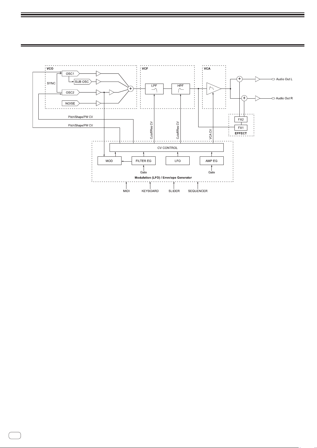
36
En
Block diagram
Block diagram (signal flow diagram)

37
En
Additional information
Additional information
Troubleshooting
! If you think that there is something wrong with this unit, check the items below and access the Pioneer DJ site and check [FAQ] for the [TORAIZ
AS-1].
http://pioneerdj.com/
Sometimes the problem may lie in another component. Inspect the other components and electrical appliances being used. If the problem cannot
be rectified, ask your nearest Pioneer authorized service center or your dealer to carry out repair work.
! This unit may not operate properly due to static electricity or other external influences. In this case, proper operation may be restored by turning the
power off, then turning the power back on.
! If the system operation with a connected external device(s) or the operation of this unit is unstable, try resetting the related item(s) after you
initialize [Global Setting] by performing [Reset Globals] of the [GLOBAL SETTING] menu.
Problem Check Remedy
The power of the unit does not turn on.
No indicator lights up.
Are the power cord and the AC adaptor connected
properly?
Connect the included power cord to the wall outlet properly.
Connect the included power cord to the included AC adaptor
properly.
Connect the included AC adapter’s connection cable to this unit
properly.
Is the [u] button switched on? Press the [u] button to turn on the unit.
A button indicator(s) is/are lit but nothing
appears on the display.
Isn’t the screen saver working? Operate any control and button.
Haven’t you pressed the [u] button on the rear panel while
pressing any button on the control panel?
Turn off the unit and turning it on again without pressing any
button other than the [u] button.
No sound or low sound Is the [VOLUME] control on the control panel set in the
proper position?
Is the level or volume of each category/parameter set
properly?
Turn the [VOLUME] on the control panel to the proper position.
Set the level or volume of each category/parameter to the proper
value.
Are the following set properly?
! [LPF CUTOFF] and [HPF CUTOFF] controls on the
control panel
! [Cutoff] and [Key Amount] parameters of the [LOW-
PASS FILTER] and [HIGH-PASS FILTER] categories
Set the following properly.
! [LPF CUTOFF] and [HPF CUTOFF] controls on the control
panel
! [Cutoff] and [Key Amount] parameters of the [LOW-PASS
FILTER] and [HIGH-PASS FILTER] categories
Distorted sound Is the level or volume of each category/parameter set to
proper value?
Is the filter resonance set to proper value?
Set each category/parameter and filter resonance to proper
values.
The sequencer and arpeggiator do not work.
(Internal synchronous operation)
Is [MIDI Clock Mode] of the [GLOBAL SETTING] menu set
to [Master] or [Off]?
Set [MIDI Clock Mode] to [Master] or [Off].
The sequencer and arpeggiator do not work.
(External synchronous operation)
Is a MIDI cable properly connected? Connect the MIDI OUT terminal of the external device and [MIDI
IN] of this unit using a MIDI cable properly.
Is MIDI clock sent from an external MIDI device? Check that the external MIDI device is set to master mode.
Is [MIDI Clock Cable] of the [GLOBAL SETTING] menu
set properly?
Set [MIDI Clock Cable] to [MIDI Port] or [USB], whichever
receives MIDI Clock.
Controls and buttons on the control panel
do not work even if you turn them right or
left.
Is [Local Control] of the [GLOBAL SETTING] menu set
to [On]?
Set [Local Control] to [On].
MIDI SysEx (system exclusive) data cannot
be sent nor received.
Is a MIDI cable properly connected? Connect an external MIDI device and [MIDI] terminals of this unit
using MIDI cables properly.
Is a USB cable properly connected? Connect you PC and the [USB-B] terminal of this unit directly
using a USB cable which conforms to USB 2.0. USB hubs cannot
be used.
Is [MIDI Sysex Cable] of the [GLOBAL SETTING] menu
properly set?
Set [MIDI Sysex Cable] to [MIDI Port] or [USB] properly,
whichever sends and receives SysEx data.
Is [MIDI Out Select] of the [GLOBAL SETTING] menu
properly set?
Set [MIDI Out Select] to [MIDI Port] or [USB] properly, whichever
sends and receives SysEx data.
Tuning is off. Is [Master Coarse] or [Master Fine] of the [GLOBAL
SETTING] menu properly set?
Set [Mater Coarse] or [Master Fine] to the proper value.
Did you perform calibration? Perform calibration by selecting [Calibrate] in the [GLOBAL
SETTING] menu at least ten minutes after the unit has been
turned on.
Is the slider in latch mode and pitch bend working? If the [LATCH] button is lit, press the [LATCH] button to turn off
the latch mode.
Keyboard operation is unstable.
— Sound comes out even if you do not
touch the keyboard.
— The range where sound comes out is
narrow.
Is [Keys Sens] of the [GLOBAL SETTING] menu set
properly?
Set [Keys Sens] to a proper value.
Haven’t you pressed the [u] button on the rear panel while
touching any keyboard key?
Turn off the unit and turning it on again by pressing the [u] button
without touching any keyboard key nor slider.
! The TORAIZ AS-1’s keyboard is an electrostatic capacitive
touch pad and calibration for the keyboard touch sensitivity is
performed when you turn on the unit.

38
En
Precautions regarding our repair
services
! When we repair your unit, we may need to reset the unit to its factory
defaults, depending on the condition of the unit. Since we do not
back up your settings prior to repair, we recommend that you back
up your original settings (such as your edited programs) as System
Exclusive files via MIDI interface. To do this, use a DAW or other MIDI
Utility software that can transmit and receive MIDI System Exclusive
messages.
About trademarks and registered
trademarks
! "Pioneer DJ" is a trademark of PIONEER CORPORATION, and is used
under license.
! Dave Smith Instruments and Prophet are registered trademarks of
Dave Smith Instruments LLC.
Specifications
AC adapter
Power ............................................................ AC 100 V to 240 V, 50 Hz/60 Hz
Rated current ......................................................................................... 0.4 A
Rated output ................................................................................. DC 5 V, 2 A
Power consumption (standby) ........................................................ 0.075 W
General - Main Unit
Power consumption ............................................................DC 5 V, 1500 mA
Main unit weight ....................................................................1.4 kg (3.1 lbs.)
Max. dimensions
........................... 267.4 mm (width) x 68.6 mm (height) x 177.7 mm (depth)
(10.5 in. (width) × 2.7 in. (height) × 7.0 in. (depth))
Tolerable operating temperature .........+5 °C to +35 °C (+41 °F to +95 °F)
Tolerable operating humidity ...................... 5 % to 85 % (no condensation)
Input/Output terminals
AUDIO OUT R output terminal
1/4˝ TS jack .......................................................................................1 set
AUDIO OUT L output terminal
1/4˝ TS jack .......................................................................................1 set
PHONES output terminal
1/4˝ stereo phone jack .....................................................................1 set
MIDI OUT/THRU output terminal
5P DIN ...............................................................................................1 set
MIDI IN input terminal
5P DIN ...............................................................................................1 set
TRIGGER IN input terminal
1/4˝ TS jack .......................................................................................1 set
USB terminal
B type ................................................................................................. 1 set
! The specifications and design of this product are subject to change
without notice.
! © 2017 Pioneer DJ Corporation. All rights reserved.
<DRI1434-A>
