Loading ...
Loading ...
Loading ...
7
PUSH PUSH
POWER
CONTROL
OUT IR IN
IN
RS232C
DATA IN
SERVICE
PORT
RAA2
AM
ANT
FM
ANT
A059770 MR89 REAR UPPER 1/14/22 JM FILM 2/3/22 REVISED FILM 3/24/22
MR89 AM/FM TUNER
McINTOSH LABORATORY, INC., BINGHAMTON, NY
HANDCRAFTED IN USA WITH US AND IMPORTED PARTS
120V 50/60Hz
30 WATTS
LR
BALANCED
L
R
UNBAL
DIGITAL
OPTICAL
COAXIAL
SERIAL
NUMBER
OUTPUTS
CAUTION
RISK OF ELECTRIC SHOCK
DO NOT OPEN
A059771 MR89 CHASSIS WHITE INK 1/14/22 JM FILM 2/3/22
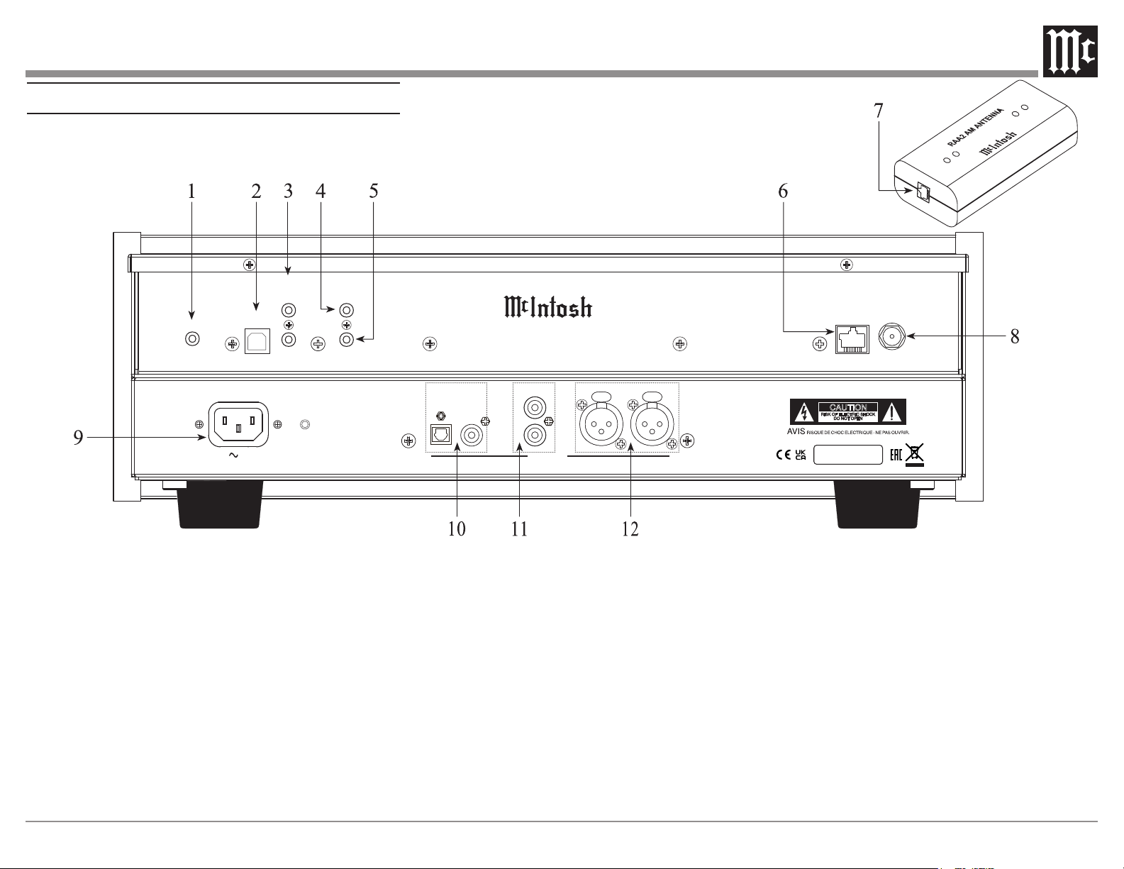
Rear Panel and RAA2 Connections
1 RS232 connector for communications with
an external control device
2 Used for upgrading the MR89 Firmware
3 POWER CONTROL IN receives power
and light control signals from a McIntosh
component (5-15 Volts ON, 0 Volts OFF).
POWER CONTROL OUT sends out a 12V
power control signal, and passes the light
control signal received at power control in
to another McIntosh Component when the
MR89 is On.
4 IR Input for connecting an IR Receiver
5 DATA IN receives operating data from a
McIntosh Preamplier or Control Center
6 AM ANT (Antenna) connector allows a
McIntosh RAA2 Remote Antenna to be
connected
7 Connect to the RAA2 AM ANT connector
on MR89 using the supplied cable
8 75 OHM FM ANT (Antenna) connects to
an external FM Antenna or cable
9 Connect the MR89 power cord to a live
AC outlet. Refer to information on the
back panel of your MR89 to determine the
correct voltage for your unit
10 COAXIAL AND OPTICAL DIGITAL
AUDIO OUTPUTS send signals to a
Preamplier or Control Center with a D/A
Converter or a decoder
11 UNBALANCED AUDIO OUTPUTS
supply analog audio signals to Unbalanced
Inputs of other components
12 BALANCED AUDIO OUTPUTS supply
analog audio signals to Balanced Inputs of
other components
Loading ...
Loading ...
Loading ...