Loading ...
Loading ...
Loading ...
24
NOTE:
These conversions should only be carried out by qualified persons. All connections must
be checked for leaks before re-commissioning the appliance.
Adjustment of components that have adjustments / settings sealed (e.g. paint sealed) can
only be adjusted in accordance with following instructions and shall be re-sealed before re
-commissioning this appliance.
For all relevant gas specifications, refer to ‘Gas Specifications’ table at end of this section.
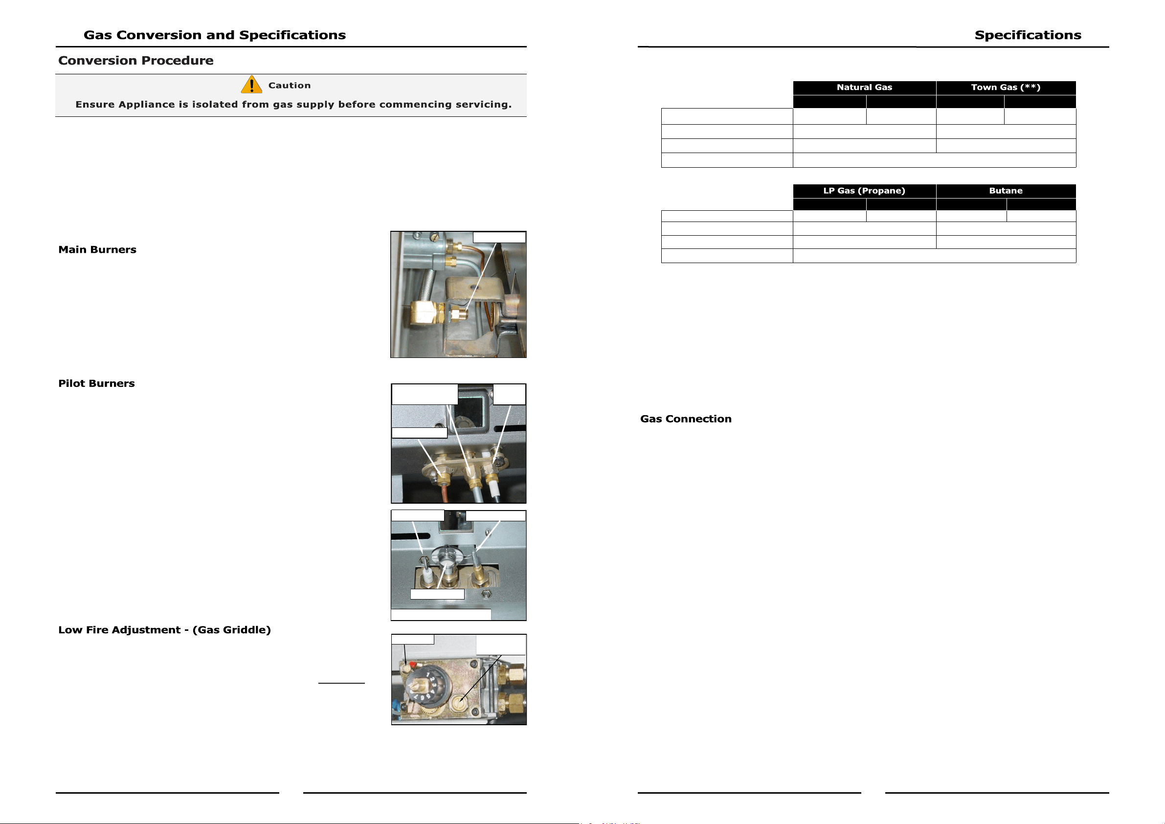
1. Remove the following:-
Gas control knobs.
Control Panel.
Disconnect electrical connection lead from rear of piezo
igniters.
2. Remove main burner injectors and replace with correct size
injectors as shown in ‘Gas Specifications Tables’ at rear of
this section.
1. Carry out the following:-
Lead to piezo igniter.
Unscrew and remove piezo igniter.
Slacken gas supply tube at gas control end.
Disconnect gas supply tube to pilot burner.
2. Remove pilot injectors and replace with correct size injectors as
shown in ‘Gas Specifications Tables’ at rear of this section.
3. Reconnect the following:-
Gas supply tube to pilot burner.
Tighten gas supply tube at gas control end.
Refit piezo igniter.
Re-connect lead to piezo igniter.
To change gas griddle thermostat ‘Low Fire’ adjustment, low fire screw on
gas control valve should be screwed fully in, then un-screwed by 1 full
turn as shown in ‘Gas Specifications’ table at end of this section.
1. Screw ‘Low Fire’ screw fully ‘IN’ and then unscrew by 1 Full Turn of
‘Low Fire’ screw. (Refer to ‘Gas Specification’ table at rear of this
section).
2. Ensure Gas Control Pilot Screw is adjusted to 3 turns out c.c.w.
3. Refit control panel
4. Refit gas control knob.
NOTE: ‘Low Fire Screw’ should be sealed with coloured paint on completion of low fire adjustment
Main Injector
Piezo
Igniter
Pilot Injector Gas
Supply Pipe
Thermocouple
Thermocouple
Pilot Injector
Piezo Igniter
Viewed from inside Burner Box
Low Fire
Adjust Screw
Pilot Screw
5
- All Other Markets
(*) NOTE:
(*) Measure burner operating pressure at at gas valve outlet test point with burner
operating at 'High Flame' setting.
NAT, LPG & Butane Only - Operating pressure is ex-factory set and is not to be adjusted,
unless when converting between gases, if required.
(**) TOWN GAS Only - Adjust burner operating pressure using adjustable gas regulator
supplied.
Refer to ‘Gas Conversion and Specifications' section in this manual for further details.
Gas supply connection point is located 130mm from right hand side of appliance, 32mm from rear,
655mm from floor and is entered from beneath appliance. An optional underside connection is
available.
Connection is ¾” BSP male.
GP8910GE/GEC GP8121GE/GEC GP8910GE/GEC GP8121GE/GEC
Input Rating (N.H.G.C.) 80 MJ/hr 108 MJ/hr 80 MJ/hr 108 MJ/hr
Supply Pressure 1.13 - 3.40 kPa 0.75 - 1.50 kPa
Burner Operating Pressure (*) 0.90 kPa 0.45 kPa
Gas Connection ¾” BSP Male
GP8910GE/GEC GP8121GE/GEC GP8910GE/GEC GP8121GE/GEC
Input Rating (N.H.G.C.) 80 MJ/hr 108 MJ/hr 80 MJ/hr 108 MJ/hr
Supply Pressure 2.75 - 4.50 kPa 2.75 - 4.50 kPa
Burner Operating Pressure (*) 2.6 kPa 2.6 kPa
Gas Connection ¾” BSP Male
Loading ...
Loading ...
Loading ...