Loading ...
Loading ...
Loading ...
10
NOTE: ALL GAS FITTING MUST ONLY BE CARRIED OUT BY A QUALIFIED PERSON.
1. It is essential that gas supply is correct for appliance to be installed and that adequate supply
pressure and volume are available. The following checks should be made before installation:-
a. Gas Type appliance has been supplied for is shown on
coloured stickers located above gas connection and on rating
plate. Check that this is correct for gas supply appliance is
being installed for. Gas conversion procedure is detailed in
this manual.
b. Supply Pressure required for this appliance is show n
in Specifications section of this manual. Check gas supply to
ensure adequate supply pressure exists.
c. Input Rate of this appliance is stated on Rating Plate and in
Specifications section of this manual. Input rate should be
checked against available gas supply line capacity. Particular
note should be taken if appliance is being added to an
existing installation.
NOTE: It is important that adequately sized piping runs directly to connection joint on appliance
with as few tees and elbows as possible to give maximum supply volume.
2. Fit gas regulator supplied, into gas supply line as close to appliance as possible.
NOTE: Gas pressure regulator provided with this appliance is convertible between Natural Gas and
LPG as per ‘Gas Conversion Section’ in this manual.
Ensure regulator is converted to correct gas type that appliance will operate on.
Regulator outlet pressure is fixed ex-factory for gas type that regulator is converted to and it
is NOT to be adjusted.
Regulator connections are
3
/
4
" BSP female.
Connection to appliance is
3
/
4
" BSP male.
(Refer to Specifications section for gas supply location dimensions).
NOTE: A Manual Isolation Valve must be fitted to individual appliance supply line.
3. Correctly locate appliance into its final operating position and using a spirit level, adjust legs so that
unit is level and at correct height.
4. Connect gas supply to appliance. A suitable jointing compound which resists breakdown action of
LPG must be used on every gas line connection, unless compression fittings are used.
5. Check all gas connections for leakages using soapy water or other gas detecting equipment.
6. Check gas operating pressure is as shown in Specifications section.
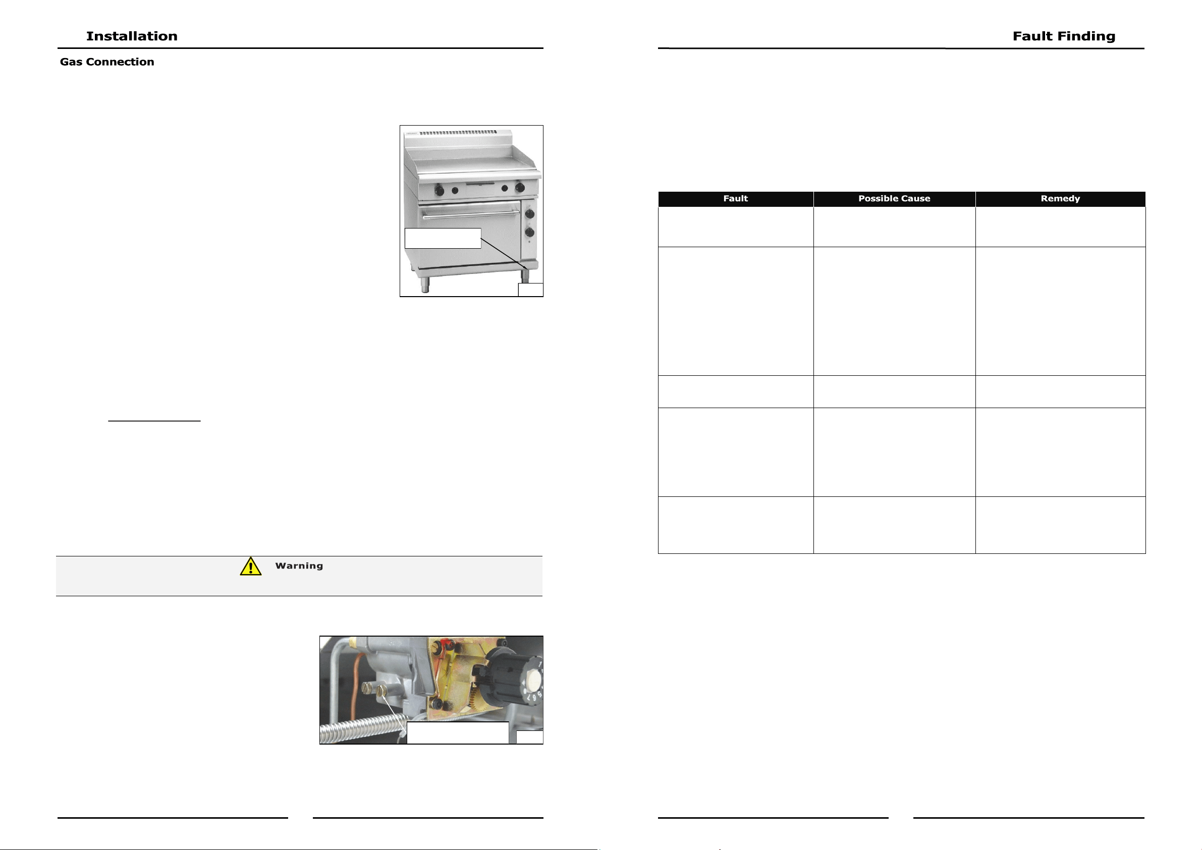
NOTE: Measure operating pressure at burner
operating pressure test point outlet with
one burner operating at 'High Flame'
setting.
7. Verify operating pressure remains correct.
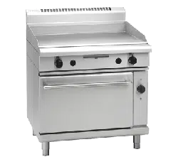
Rating Plate will be
located in this area
Fig 2
Burner Operating Pressure
Test Point (Outlet).
Fig 3
DO NOT USE A NAKED FLAME TO CHECK FOR GAS LEAKAGES.
19
This section provides an easy reference guide to the more common problems that may occur during
operation of your appliance. The fault finding guide in this section is intended to help you correct, or at
least accurately diagnose problems with your equipment.
Although this section covers the most common problems reported, you may encounter a problem not
covered in this section. In such instances, please contact your local authorised service agent who will
make every effort to help you identify and resolve the problem. Please note that the service agent will
require the following information:-
Model Trade Name and Serial Number of Appliance. (both can be found on Technical
Data Plate located on appliance.
NOTE: Components having adjustments protected (e.g. paint sealed) by manufacturer, are only to
be adjusted by an authorised service agent. They are not to be adjusted by an unqualified
service person.
Pilot will not light. No gas supply.
Blocked pilot injector.
Ensure gas isolation valve is turned On, and
that bottles are not empty.
Call service provider.
Pilot goes out when gas control
knob released.
Releasing knob before thermocouple has
heated.
Pilot flame too small.
- Gas pressure too low.
- Partially blocked pilot injector.
Thermocouple connection to gas control
is loose or faulty.
Thermocouple faulty.
Hold knob in for at least 20 seconds
following ignition of pilot.
Clean or replace pilot injector.
Tighten thermocouple connection.
Inspect and replace if not in good working
order.
Call service provider.
Main burner will not light. Incorrect supply pressure.
Faulty gas control.
Call the service provider.
Oven element does not work when
turned ON.
Check individual fuses located behind
control panel.
Check for an electrical short by checking
that there is NO continuity between any
"phase in" line and metal appliance body
itself.
Check for item failing (element, control
etc) by using a multimeter.
Replace blown fuse.
Call service provider.
Call service provider.
Complete power failure of appli-
ance
Check fuse connection at mains supply.
Ensure fuse size is correct to carry load.
Check for an electrical short to appliance.
Replace blown fuse.
Carry out a continuity and resistance check
on appliance.
Call service provider.
Loading ...
Loading ...
Loading ...