Loading ...
Loading ...
Loading ...
4
- Australia
- New Zealand Only:
- UK Only:
Category: II
2H3P
(20, 37).
Flue Type: A
1.
* - Measure burner operating pressure at gas control valve outlet test point with one burner
operating at ‘High’ setting. Operating pressure is ex-factory set, through the appliance
regulator and not to be adjusted, apart from when converting between gases, if required.
(Refer to ‘Gas Conversion’ section for details).
GP8910GE/GEC GP8121GE/GEC GP8910GE/GEC GP8121GE/GEC
Heat Input (nett) 21 kW 28.5 kW 21 kW 28.5 kW
Gas Rate (nett) 2.22 m
3
/hr 3.02 m
3
/hr 1.63 kg/hr 2.21 kg/hr
Supply Pressure 20 mbar 37 mbar
Burner Operating Pressure (*) 8.2 mbar 26 mbar
Gas Connection
3
/
4
” BSP Male
GP8910GE/GEC GP8121GE/GEC GP8910GE/GEC GP8121GE/GEC
Input Rating (N.H.G.C.) 80 MJ/hr 108 MJ/hr 80 MJ/hr 108 MJ/hr
Supply Pressure 1.13 - 3.40 kPa 2.75 - 4.50 kPa
Burner Operating Pressure (*) 0.90 kPa 2.6 kPa
Gas Connection ¾” BSP Male
GP8910GE/GEC GP8121GE/GEC GP8910GE/GEC GP8121GE/GEC
Input Rating (N.H.G.C.)
80 MJ/hr 108 MJ/hr 80 MJ/hr 108 MJ/hr
Supply Pressure 1.13 - 3.40 kPa 2.75 - 4.50 kPa
Burner Operating Pressure (*) 0.90 kPa 2.6 kPa
Gas Connection ¾” BSP Male
25
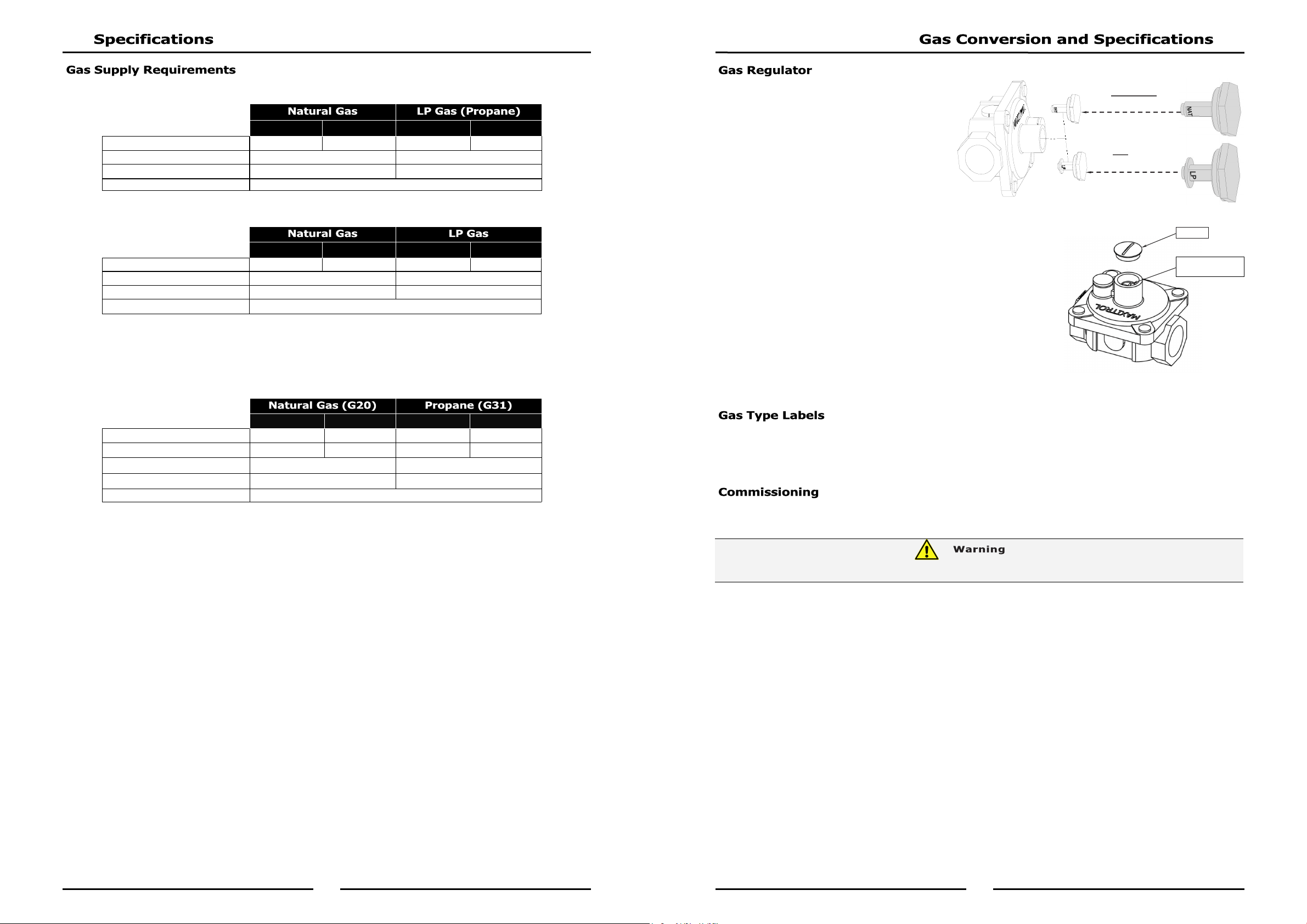
NOTE, Pin rotated
for Natural Gas
NOTE, Pin rotated
for LPG
- NAT Gas / LPG / Butane Only.
NOTE: Gas regulator supplied is
convertible between Natural Gas
and LP Gas, but it’s outlet
pressure is fixed ex-factory and
is NOT to be adjusted.
- Town Gas Only.
1. Remove slotted cap from regulator.
2. Turn ‘On’ gas supply and appliance.
3. Adjust pressure adjusting screw to achieve correct burner
operating pressure.
NOTE: Measure burner operating pressure at gas valve outlet
test point with burner operating at 'High Flame'
setting.
4. Verify operating pressure remains correct (Re-adjust
regulator if required).
5. Screw cap nut back onto regulator.
On completion of gas conversion, replace gas type labels located at:-
- Rear of unit, above gas connection.
- Beside rating plate.
Before leaving installation;
1. Check all gas connections for leakage using soapy water or other gas detecting equipment.
2. Carry out a ‘Commissioning’ check of appliance as shown in Installation Section of this manual.
3. Ensure any adjustments done to components that have adjustments / settings paint sealed are to be
re-sealed.
NOTE: If for some reason it is not possible to get the appliance to operate correctly, shut off the
gas supply and contact the supplier of this appliance.
DO NOT USE A NAKED FLAME TO CHECK FOR GAS LEAKAGES.
Pressure Adjusting
Screw
Cap Nut
Loading ...
Loading ...
Loading ...