Loading ...
Loading ...
Loading ...

15
4
Connect the external power supply to the transmitter unit and
plug the transmitter unit into a Tripp Lite Surge Suppressor, Power
Distribution Unit (PDU) or Uninterruptible Power Supply (UPS). The
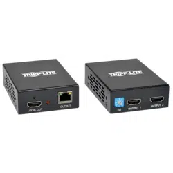
green RJ45 LEDs on the B126-002 and B126-004 and the red LED
on the B126-004 will illuminate to indicate that the unit is receiving
power from the external power supply.
5
Using Cat5e/6 cable, connect a RJ45 OUTPUT port on the transmitter
unit to the RJ45 INPUT port on the B126-110 repeater unit.
6
Connect a monitor to the HDMI OUTPUT port on the repeater unit
using a Tripp Lite P568-Series High-Speed HDMI Cable.
7
Connect the external power supply to the remote/repeater unit and
plug the remote/repeater unit into a Tripp Lite Surge Suppressor, PDU
or UPS. The green power and RJ45 LEDs will illuminate to indicate
that the unit is receiving power from the external power supply.
Up to 4 units can be daisy-chained (3 repeaters and 1 active receiver). To
add additional repeater units, proceed to step 8. To finish your installation
with a B126-2A0 1x2 receiver unit, proceed to step 11.
8
Using Cat5e/6 cable, connect the RJ45 port on the repeater unit
marked OUTPUT to the RJ45 port on a second repeater unit marked
INPUT.
9
Connect a monitor to the HDMI OUTPUT port on the repeater unit
using a Tripp Lite P568-Series High-Speed HDMI Cable.
10
Connect the external power supply to the remote/repeater unit and
plug the remote/repeater unit into a Tripp Lite Surge Suppressor,
PDU or UPS. The green power and green RJ45 LEDs will illuminate
to indicate that the unit is receiving power from the external power
supply.
Extender/Splitter with
Remote/Repeater Installation
Loading ...
Loading ...
Loading ...