Loading ...
Loading ...
Loading ...
- Water must be supplied to the appliance through a cold
water pipe that complies with hygiene standards and can
withstand the operating pressure.
Use the stainless steel hose supplied (Length 1.5 m) Do not
reuse old hoses. A 3 m hose is available as an optional
extra. This must be professionally installed.
A filter with a seal is located in the hose connector.
- A stopcock must be placed between the hose line and the
domestic water connection to cut off the water supply, if
necessary.
- All devices and equipment used to supply water must
comply with the regulations in force in the respective
country.
- Do not damage or kink the water supply line during installa-
tion.
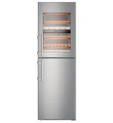
Fig. 44
The solenoid is at the bottom on the back of the appliance. It
has a metric R3/4 connecting thread.
For specialist staff:
The back of the appliance must be accessible to connect the
stainless steel hose:
WARNING
Risk of injury.
Cuts from a broken auxiliary tool
Fig. 44 (6)
.
u
Only use an auxiliary tool
Fig. 44 (6)
at room temperature.
u
Slide the nut
Fig. 44 (4)
over the straight end of the hose
Fig. 44 (3)
up to the end and secure.
u
Insert the filter
Fig. 44 (2)
into the nut
Fig. 44 (4)
.
w
The filter
Fig. 44 (2)
rests flat on the straight end of the hose
Fig. 44 (3)
and is easily retained.
u
Connect the nut
Fig. 44 (4)
to the cut-off valve
Fig. 44 (3)
with the filter resting on the straight end of the hose
Fig. 44 (2)
.
u
Open the water supply cut-off valve
Fig. 44 (1)
temporarily to
bleed the water pipe and fill it with water. Keep the hose in a
bucket.
u
Remove the cover
Fig. 44 (10)
.
u
Slide the nut
Fig. 44 (7)
over the angled end of the hose
Fig. 44 (8)
up to the end and secure.
u
Moisten the seal
Fig. 44 (9)
and push into the nut
Fig. 44 (7)
on the end of the angled hose
Fig. 44 (8)
.
w
The seal
Fig. 44 (9)
lies flat on the angled end of the hose
Fig. 44 (8)
and is easily retained.
NOTICE
Risk of damaging the threads of the solenoid.
u
Locate the nut carefully and screw onto the thread.
u
Connect the nut
Fig. 44 (7)
to the solenoid
Fig. 44 (8)
with
the seal resting on the
Fig. 44 (9)
angled end of the hose
Fig. 44 (11)
.
u
Tighten connections with the auxiliary tool
Fig. 44 (6)
clock-
wise until the maximum torque is reached and the auxiliary
tool
Fig. 44 (6)
is overwound.
u
Open the water supply cut-off valve
Fig. 44 (1)
and check
the whole water system for leaks.
u
Hook the clip
Fig. 44 (5)
into the auxiliary tool
Fig. 44 (6)
and
fix it to the stainless steel pipe to store it.
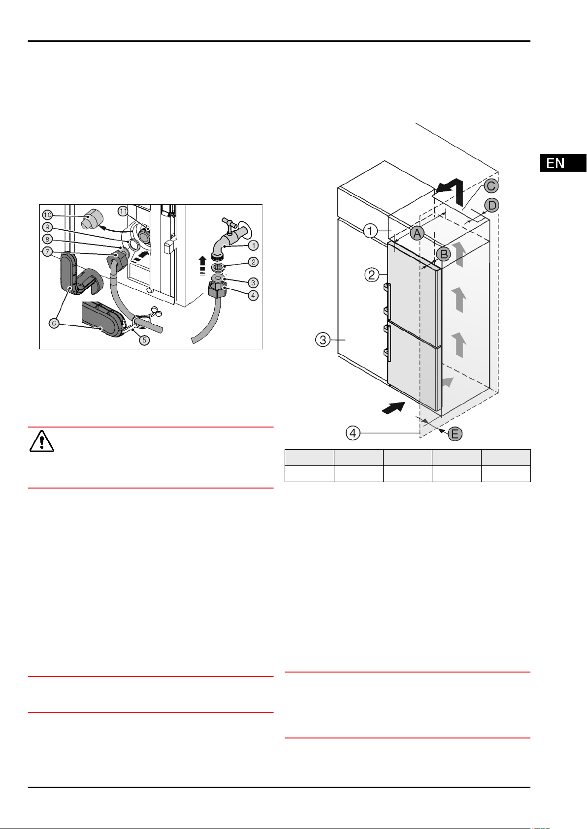
4.5 Insertion into a row of kitchen units
Fig. 45
A [mm] B [mm]
C [cm
2
]
D [mm] E [mm]
665
x
65 Min. 300 Min. 50 Min. 46
x
If wall spacers are used, the dimensions increase by 15 mm
(see 4.2) .
The dimensions apply for an opening angle of 90 °. Spacing
angles will vary according to the opening angle.
You can purchase a kit to limit the door opening angle to 90° on
soft closing appliances. Please contact our customer service
team.
The appliance can be built into kitchen units. A top cupboard
Fig. 45 (2)
can be added above the appliance in order to bring
the appliance
Fig. 45 (1)
up to the height of the fitted kitchen
units.
The appliance can be installed right next to the kitchen cabinet
Fig. 45 (3)
. The appliance must stick out by the depth
Fig. 45 (B)
from the front of the cabinet so that the doors can be
opened fully. The appliance may protrude further depending on
the depth of the kitchen cabinets and whether wall spacers are
used.
NOTICE
Danger of overheating due to insufficient air ventilation!
The compressor may be damaged if there is insufficient air
ventilation.
u
Take care to ensure adequate air ventilation.
u
Observe the ventilation requirements.
Ventilation requirements:
Putting into operation
* Depending on model and options 17
Loading ...
Loading ...
Loading ...