Loading ...
Loading ...
Loading ...
u
Insert the holder with its cable into the opening.
Fig. 35 (5)
u
Press the holder downwards until the tab clicks into place.
Fig. 35 (6)
u
Insert the plugs.
Fig. 35 (7)
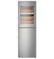
4.3.13 Fitting the cable connection
Fig. 36
u
Engage the plug above the upper bearing bracket and care-
fully place the cable strands into the channel.
Fig. 36 (1)
u
Carefully position the grey cable in the guide above the top
bearing bracket.
Fig. 36 (2)
Fig. 37
u
Insert the grey cable into the guide in the top door.
Fig. 37 (1)
u
Engage the plug.
Fig. 37 (2)
u
Position the remaining cable length as a loop in the guide, if
required.
4.3.14 Aligning the doors
WARNING
Risk of injury due to the door dropping out!
If the bearing parts are not screwed into place firmly enough,
the door may drop out. This may lead to severe injuries. What is
more, the door may not close and therefore the appliance may
fail to cool properly.
u
Screw the turn hinges firmly into place with 4 Nm.
u
Check all of the screws and retighten if necessary.
u
Align the doors flush with the appliance housing using the
two oblong holes in the lower bearing bracket and centre
bearing bracket if needed. To do this undo the middle screw
in the bottom bearing bracket with the T25 tool supplied.
Undo the remaining screws a little with the T25 tool or with a
T25 screwdriver and align using the slotted holes. Undo the
screws in the middle bearing bracket with the T25 tool and
align the middle bearing bracket using the slotted holes.
u
Support the door: Take off the adjustable foot on the bearing
bracket using the open-ended wrench SW10 until it comes
into contact with the floor, then turn an additional 90°.
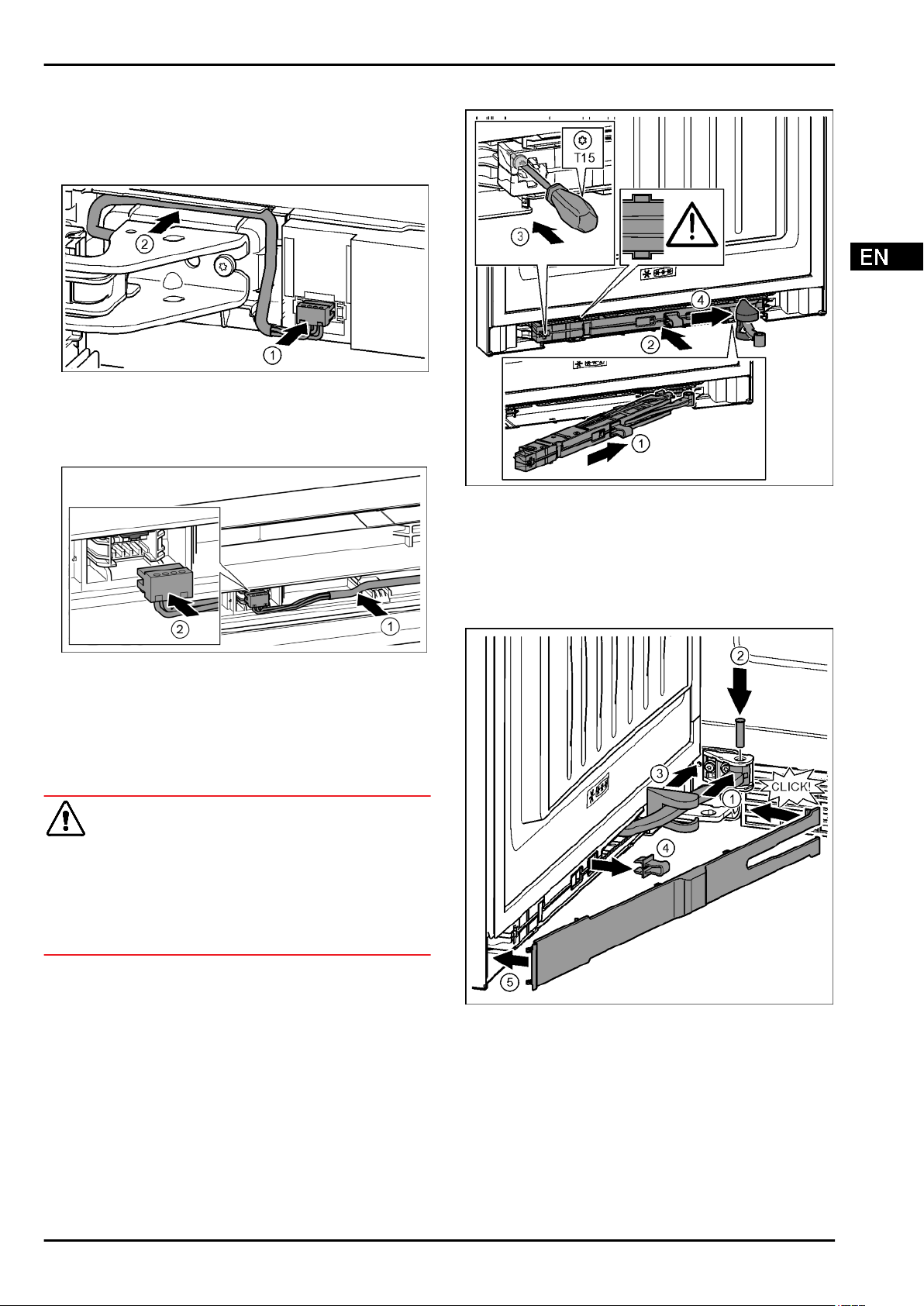
4.3.15 Fit the bottom soft stop mechanism
Fig. 38
u
Slide the soft stop mechanism on the bearing bracket side at
an angle into the slot as far as the limit stop.
Fig. 38 (1)
u
Slide the soft stop mechanism fully into the slot.
Fig. 38 (2)
w
The unit is positioned correctly when the rib on the soft stop
mechanism is in the guide.
u
Tighten the screw with the T15 screwdriver.
Fig. 38 (3)
u
Push the cover over the hinge.
Fig. 38 (4)
Fig. 39
The door is open 90°
u
Turn the hinge in the mount.
Fig. 39 (1)
u
Insert the bolt with a T15 screwdriver in the mount and
hinge. Make sure that the catch mechanism is sitting
correctly in the groove.
Fig. 39 (2)
u
Push the bearing bracket cover along the hinge and fit on
the mount.
Fig. 39 (3)
u
Remove the locking device.
Fig. 39 (4)
u
Position the panel on the handle side and swing it in.
Fig. 39 (5)
w
The panel is clicked into place.
u
Close the bottom door.
Putting into operation
* Depending on model and options 15
Loading ...
Loading ...
Loading ...