Loading ...
Loading ...
Loading ...
EN
30
Installation
www.bora.com
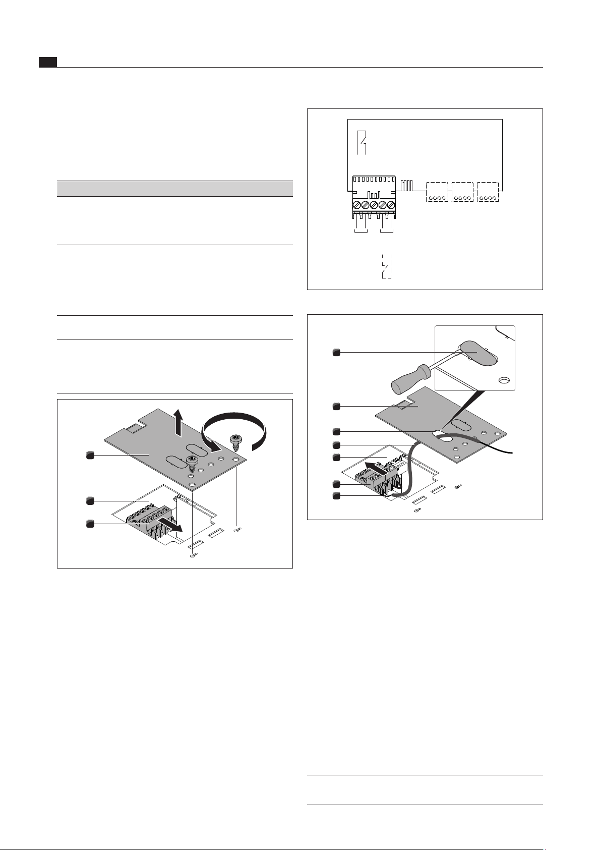
X1.1
X2.1
X1.2
X1.4
X1.5
Home
In
Home
Out
Abb. 6.42 External switch contacts connection diagram
1
4
7
6
5
3
2
Abb. 6.43 Connecting the cable
[1] Sealing cover
[2] Cover
[3] Cable opening
[4] Protective hose
[5] Electronic unit
[6] Contact plug
[7] Cable connection
Remove the sealing cover [1] for the cable opening [3]
with a screw driver.
Move the protective hose [4] onto the cable [7].
Guide the cable [7] with the protective hose [4]
through the cable opening [3] in the cover.
Remove the installed bridge.
Connect the cable for the relevant contact to the
contact plug [6] in accordance with the relevant
connection diagram (see fig. Connection diagram for
external switch contacts).
INFO The Home-In contact must be bridged if this is
not used (bridged on delivery).
When using Home-In and Home-Out, you will require the
relevant documents for the external switching devices in
order to ensure safe device connection and operation.
The following switch connections can be used:
Contact Function Connection
Home-In Cooktop extractor on/off
connection for external switch
contact (contact closed:
cooktop extractor on)
30 V DC 0.7 mA
Home-Out Electrically isolated contact
for controlling external
installations depending on
the operation of the cooktop
extractor (cooktop extractor
on: contact closed)
Maximum 250V/4A
Tab. 6.4 Home-In and Home-Out switch connections
INFO The Home-In contact can be used for external
safety devices (e.g. window contact switches).
If the switch is open, the cooktop extractor is
out of operation.
3
2
1
Abb. 6.41 Opening the cover and disconnecting the contact plug
[1] Cover
[2] Electronic unit
[3] Contact plug
Open the cover [1].
Adhere to the connection diagram when connecting
Home-In and Home-Out.
Disconnect the contact plug [3] from the electronic
unit [2].
Loading ...
Loading ...
Loading ...