Loading ...
Loading ...
Loading ...
EN
19
Installation
www.bora.com
6 Installation
Observe all safety and warning information (see the
Safety chapter).
Follow the enclosed manufacturer‘s information.
INFO The power supply cable must be provided by
the customer.
INFO The device must not be installed above cooling
devices, dishwashers, stoves, ovens, washing
machines or dryers.
INFO The contact surfaces of the worktops and wall
sealing strips must be made of a heat-resistant
material (up to approx. 100°C).
INFO Worktop cut-outs must be moisture-sealed
using suitable means and, where necessary,
fitted with a thermal insulator.
6.1 Checking the scope of delivery
Name Quantity
Surface induction glass ceramic cooktop with
cooktop extractor
1
Stainless steel grease filter 1
BAKF activated charcoal filter 2
Flexible duct (BFIU only) 1
EURO screws (BFIU only) 6
BLAVH horizontal exhaust air extension (BFIA only) 1
Mounting straps 5
Sealing tape 1
Glass ceramic scraper 1
Cable routing clips 3
Protective hose 2
Cable tie 2
Operating and installation instructions 1
Lenshead screw 5
Drilling template (BFIU only) 1
Height adjustment plate set 2
Tab. 6.1 Scope of delivery
Check the scope of delivery for damage and make sure
it is complete.
If there are any missing or damaged parts, please
notify BORA After Sales Service immediately.
Do not under any circumstances install parts which are
damaged.
Dispose of transport packaging in the proper manner
(see the Decommissioning, Disassembly and Disposal
chapter).
6.2 Tool and aids
The following tools are required for the correct installation
of the cooktop:
Pencil
Standard or cordless drill with a 5 mm wood drill
(for the rear wall)
Compass saw or hand saw
Drilling template for cut-out on rear wall
(included in scope of delivery)
Phillips screwdriver Z2
Silicone sealant for sealing cutting surfaces
6.3 Assembly instructions
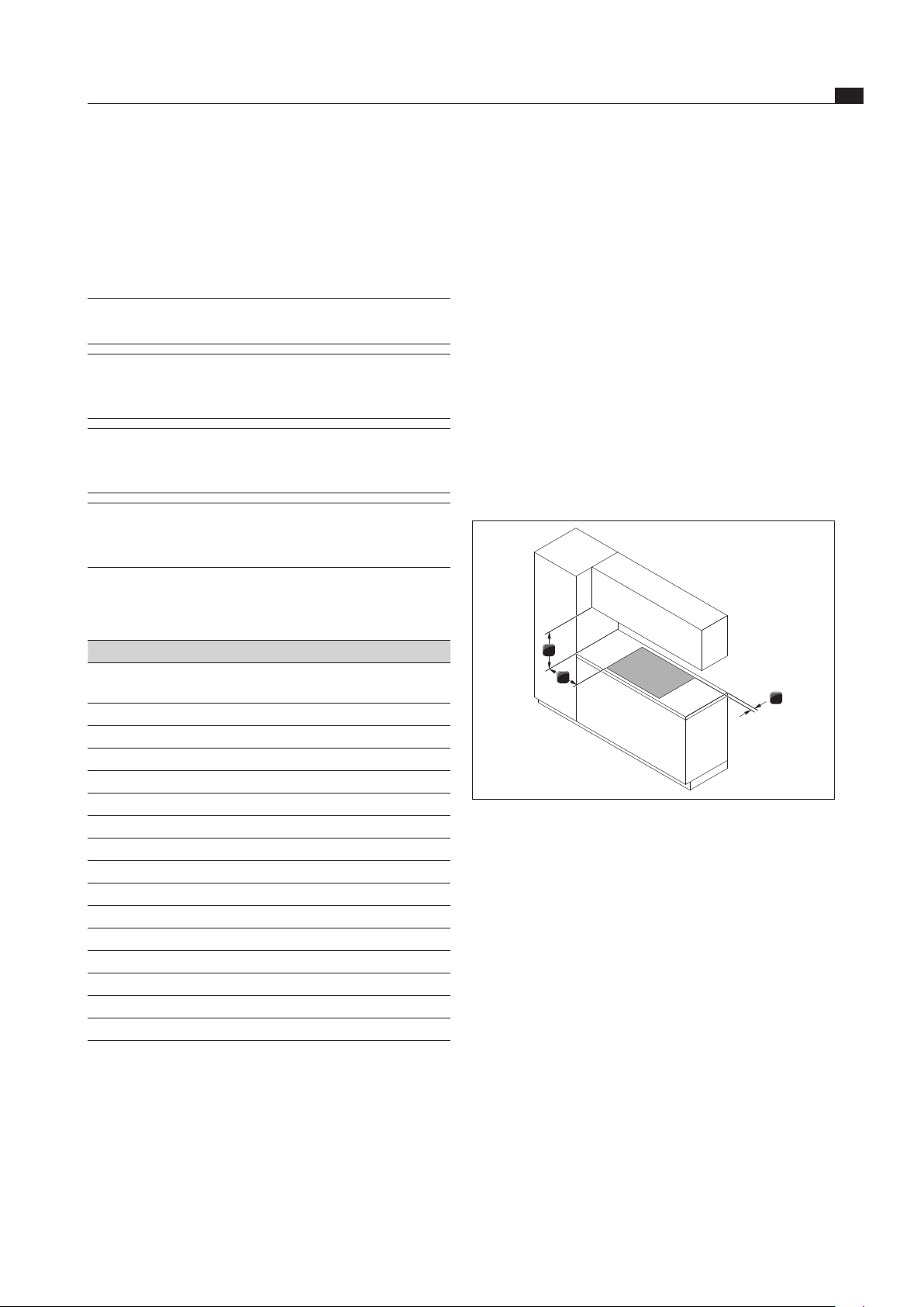
6.3.1 Safety distances
Maintain the following safety distances:
1
3
2
Abb. 6.1 Recommended minimum clearances
[1] Rear minimum clearance of 50 mm between the worktop
cut-out and the rear corner of the worktop.
[2] Minimum clearance of 300 mm from the left and right of the
worktop cut-out to the adjacent cabinet or wall.
[3] Minimum clearance of 600 mm between the worktop
and the wall unit. A minimum clearance of 1000 mm is
recommended for ergonomic reasons.
6.4 Cut-out dimensions for the
cooktop
Preparing the worktop
Create the worktop cut-out taking into account the
specified cut-out dimensions.
Make sure that the cutting surfaces of the worktops
are properly sealed.
Comply with the instructions of the worktop
manufacturer.
Loading ...
Loading ...
Loading ...