EN
BFIASUMEN-002
www.bora.com
Operating and installation instructions BFIA, BFIU
Surface induction glass ceramic cooktop with
cooktop extractor
M8800395-000

Operating and installation instructions: Original Translation
Manufacturer
BORA Vertriebs GmbH & Co KG
Prof.-Dr.-Anton-Kathrein-Straße 3
6342 Niederndorf
Austria
Contact
T +43 (0) 5373/62250-0
www.bora.com
The distribution and duplication of this document, as well as the use and disclosure of its contents are prohibited
unless expressly authorised.
© BORA Vertriebs GmbH & Co KG
All rights reserved.

EN
3
www.bora.com
Table of Contents
1 General 4
2 Safety 6
2.1 General safety precautions .................................6
2.2 Safety instructions, operation .............................7
2.3 Safety instructions, assembly ..............................9
2.4 Safety instructions, disassembly and disposal ..10
2.5 Safety instructions, spare parts ........................11
2.6 Use as intended ................................................11
3 Technical data 12
4 Energy label 13
5 Device description 14
5.1 Structure ...........................................................14
5.2 Operating panel and
operating principle ............................................15
5.3 Functional principle of the cooking zone ...........16
5.3.1 Power levels ......................................................16
5.3.2 Automatic heat up function ...............................16
5.3.3 power setting ....................................................16
5.3.4 Heat retention levels ......................................... 16
5.3.5 Bridging function ............................................... 16
5.3.6 Pause function ..................................................17
5.3.7 Timer functions .................................................17
5.3.8 Pan size recognition ..........................................17
5.3.9 Suitable cookware .............................................17
5.4 Functional principle of the cooktop extractor ...17
5.4.1 Freely adjustable power control ........................ 17
5.4.2 Automatic cooktop extractor function ...............17
5.4.3 Power setting ....................................................18
5.4.4 Automatic after-run ........................................... 18
5.4.5 Filter service display ..........................................18
5.4.6 Interface communication...................................18
5.5 Safety devices ................................................... 18
5.5.1 Residual heat display.........................................18
5.5.2 Safety shut-down ..............................................18
5.5.3 Cooking zone overheating protection ................18
5.5.4 Automatic switch-off if the button is
pressed and held ...............................................18
5.5.5 Childproofing feature .........................................18
6 Installation 19
6.1 Checking the scope of delivery .........................19
6.2 Tool and aids ..................................................... 19
6.3 Assembly instructions .......................................19
6.3.1 Safety distances ................................................19
6.4 Cut-out dimensions for the cooktop ..................19
6.5 Installing the recirculation version (BFIU) ..........21
6.6 Installing the exhaust air version (BFIA) ............24
6.6.1 Operating the cooktop extractor with a
fireplace that depends on the air in the room ...24
6.7 Establishing the power connection....................28
6.8 Device power management (overall power
reduction) ..........................................................29
6.9 Connect the external switch contact ................29
6.10 Handover to user ...............................................31
7 Operation 32
7.1 General operating instructions .......................... 32
7.2 Operating the cooktop ......................................32
7.2.1 Select cooking zone ..........................................32
7.2.2 Adjusting the power level .................................. 32
7.2.3 Changing the power level .................................. 32
7.2.4 Selecting the power setting...............................32
7.2.5 Switching the power setting off early ................32
7.2.6 Switching off the cooking zone .........................32
7.2.7 Pay attention to the residual heat display ......... 32
7.2.8 Pause function ..................................................33
7.2.9 Bridging function ............................................... 33
7.2.10 Switching on the bridging function ....................33
7.2.11 Switching off the bridging function ...................33
7.2.12 Automatic heat up function ..............................33
7.2.13 Switching off the automatic heat up function ...34
7.2.14 Heat retention level ........................................... 34
7.2.15 Using the timer function ....................................34
7.2.16 Switching the signal beep off early ...................34
7.2.17 Setting the short-time timer
(egg timer) .........................................................34
7.2.18 Switching off the short-time timer
(egg timer) early ................................................ 34
7.2.19 Setting the automatic cut-off ............................34
7.2.20 Switching off the automatic cut-off early ..........34
7.2.21 Changing the timer settings .............................. 34
7.2.22 Switching the childproofing feature on/off ....... 35
7.3 Operating the cooktop extractor ....................... 35
7.3.1 Selecting a cooktop extractor ...........................35
7.3.2 Adjusting the power level .................................. 35
7.3.3 Changing the power level .................................. 35
7.3.4 Selecting the power setting...............................35
7.3.5 Automatic cooktop extractor function ...............35
7.3.6 Switching off the automatic cooktop
extractor function ..............................................36
7.3.7 Automatic after-run ........................................... 36
7.3.8 Switching off the automatic after-run early ....... 36
7.3.9 Switching off the cooktop extractor .................. 36
7.4 Pay attention to the filter service display .......... 36
7.5 Saving energy ....................................................36
8 Cleaning and maintenance 37
8.1 Cleaning agents .................................................37
8.2 Maintaining the cooktop ...................................37
8.3 Cleaning the cooktop ........................................37
8.4 Cleaning the cooktop extractor .........................38
8.4.1 Removing the air inlet nozzle and
stainless steel grease filter ...............................38
8.4.2 Cleaning the air inlet nozzle and
stainless steel grease filter ...............................38
8.4.3 Installing stainless steel grease filter
and air inlet nozzle ............................................38
8.5 Cleaning the air guiding housing .......................38
8.5.1 Opening the air guiding housing ........................38
8.5.2 Closing the air guiding housing .........................39
8.6 Replacing the activated charcoal filter ..............39
9 Troubleshooting 41
10 Decommissioning, disassembly
and disposal 42
10.1 Decommissioning .............................................. 42
10.2 Disassembly ......................................................42
10.3 Disposing of the product in an
environmentally friendly way ............................. 42
11 Warranty, service and spare parts 43
11.1 Warranty ............................................................43
11.2 Service ..............................................................43
11.3 Spare parts ........................................................43

EN
4
General
www.bora.com
1 General
Target group
These operating and assembly instructions are intended
for the following target groups:
Target group Requirements
Users The Device may be used by children
from the age of 8 as well as by people
with limited physical, sensory or mental
capabilities or a lack of experience and/or
knowledge, provided they are supervised,
have been instructed in the safe use of the
device and have understood the dangers
involved. Children must be supervised. All
safety and warning information and handling
instructions in the operating manual must
be followed.
Ambitious Diyers Ambitious Diyers may carry out all the
necessary carpentry and assembly work
themselves providing that they have the
necessary skills and knowledge. They must
not connect the current and gas themselves.
Assembly
expert
The assembly expert must carry out all the
necessary carpentry and assembly work
taking existing regulations into account.
The current and gas connections must be
approved for the system in use by a certified
electrician or gas engineer before use.
Electrical
expert
The electrical connection must only be
executed by a certified electrician. He/she
also assumes responsibility for the proper
electrical installation and commissioning.
Expert
gas connection
The gas connection must only be implemen-
ted by a certified gas engineer. He/she also
assumes responsibility for the proper gas
installation and commissioning.
Tab. 1.1 Target groups
INFO BORA Holding GmbH, BORA Vertriebs
GmbH & Co KG, BORA APAC Pty Ltd and BORA
Lüftungstechnik GmbH - hereinafter referred
to as BORA - shall not assume any liability for
damage caused by non-compliance with these
documents nor by improper assembly!
The electricity and gas connections must be
implemented by a certified engineer.
Assembly must only take place in compliance
with the applicable norms, regulations and
laws. All safety and warning information and
handling instructions in the operating and
assembly instructions must be followed.
Validity of the operating and assembly
instructions
This manual is valid for several versions of the device.
For this reason, it is possible that individual features are
described in the manual that do not apply to your device.
Other applicable documents
Additional documents are valid as well as these operating
and assembly instructions, and likewise need to be
observed.
Please observe all documents included in the scope of
delivery.
INFO BORA cannot assume any liability for damage
caused by non-compliance with these
documents!
Guidelines
These devices meet the following EC guidelines:
2014/30/EC EMC Directive
2014/35/EC Low-Voltage Directive
2009/125/EC Ecological Design Directive
2010/30/EC Energy label Directive
2011/65/EC RoHS Directive
2012/19/EC WEEE Directive
Depiction of information
We used standard formatting, numbering, symbols, safety
instructions, terms and abbreviations so that you can
work quickly and safely when using this manual.
Instructions are marked with an arrow.
Always perform all instructions in the prescribed order.
Enumerations are indicated with a square bullet point at
the start of the line.
Enumeration 1
Enumeration 2
INFO Information notes point to special features that
must be taken into account.
Safety and warning instructions
The safety and warning instructions in this manual are
emphasised with symbols and signal words.
Safety and warning instructions are structured as follows:
WARNING SYMBOL AND
SIGNAL WORD!
Type and source of the danger
Results of non-compliance
Measures to minimise risk
EN
5
General
www.bora.com
Please note:
The warning symbol draws your attention to the risk.
The signal word indicates the severity of that risk.
Warning
symbol
Signal word Risk
Danger Indicates an immediate,
hazardous situation which
causes death or serious injury if
not respected.
Warning Indicates a potentially
hazardous situation which can
cause death or serious injury if
not respected.
Caution Indicates a possible
hazardous situation which
can cause minor injury if not
respected.
— Caution Indicates a situation which
can cause minor injury if not
respected.
Tab. 1.2 Meaning of the warning symbols and signal words

EN
6
Safety
www.bora.com
2 Safety
2.1 General safety precautions
INFO The product complies with the
mandatory safety provisions.
The user is responsible for cleaning,
care and safe use of the device.
Any improper use may lead to
personal injury and property damage.
This operating and installation instructions
contain important information concerning
assembly and operation. It protects you
from injury and prevents damage to the
product. You can find contact data to get
further information and answers to questions
about the use of the product on the last
page of this operating and installation
instructions.
The term “device” is used to refer to cook-
top, cooktop extractor or cooktop with
integrated cooktop extractor.
Read this operating and installation
instructions in full before you assemble the
device and start to use it.
Always keep these operating and installation
instructions to hand so it is available when
needed.
After selling the device, pass on the
operating and installation manual to the
new owner.
Carry out all work with great care and
attention.
Check the device for visible damage after
unpacking.
Do not install a damaged device.
Do not use the device until installation is
complete. Only in this way a safe operation
can be guaranteed.
Make sure contact with hot cooking surfaces
is not possible.
Avoid over-cooking.
Pay attention to the residual heat indicator.
Turn the device off after use.
Do not rely on the pan size recognition.
Keep pets away from the device.
Recirculated air mode
INFO Every time the device is used for
cooking, supplementary moisture is
released into the room air.
INFO In the recirculated air mode, only
a small amount of moisture is
removed from the cooking vapours.
Make sure that the room is sufficiently ven-
tilated to the outside air in the recirculated
air mode, e.g. through an open window.
Ensure a normal and comfortable indoor
climate (45-60% humidity), e.g. through
natural ventilation openings or domestic
ventilation systems.
Set the cooktop extractor to a low setting
for about 15 minutes or activate the
automatic after-run after every use in the
recirculated air mode.
Effects on pacemakers, hearing aids and
metal implants
INFO Induction cooktops generate a high-
frequency electromagnetic field
in the area of the cooking zones.
The cooking zones may affect
pacemakers, hearing aids or metal
implants negatively or disturb their
function when in close proximity. A
reduced function of the pacemaker is
unlikely.
If in doubt, contact the manufacturer of
your medical device or your doctor.
When there are children and people with
special needs in the house
This device may be used by children from
the age of 8 as well as by persons with
limited physical, sensory or mental
capabilities or a lack of experience and/or
knowledge, provided they are supervised,
have been instructed in the safe use of the
device and have understood the dangers
involved.
Do not leave children unattended when
they are near the device.
Children must not play with the device.
Use the child safety lock in order to
prevent children from switching on the
cooktop or changing the settings when they
are unattended.
Do not store any objects that could be of
interest to children in storage spaces above
or behind the device. Otherwise, the children
will be tempted to climb onto the device.
Keep children and other persons away from
the cooking surfaces.
Unauthorised modifications
Due to unauthorised modifications
EN
7
Safety
www.bora.com
2.2 Safety instructions, operation
Cooktop
DANGER!
Danger of fire caused by leaving
the cooktop unattended!
Oil or fat in the pot can quickly heat
up and ignite.
Never leave oil or fat to heat up
unattended.
Never extinguish oil and fat fires
with water.
Suffocate the fire, for example by
using a lid.
DANGER!
Danger of explosion caused by
flammable liquids!
Flammable liquids in the vicinity of
the cooktop can explode and cause
serious injury.
Do not place any flammable liquids
in the vicinity of the
cooktop.
DANGER!
Danger of electric shock!
Cracks, ssures or fractures in the
glass ceramic panel can damage
the underlying electronics. This can
cause an electrical shock.
If there are any cracks, fissures or
fractures in the glass ceramic,
switch the device off immediately.
Safely disconnect the device from
the mains using miniature or
automatic circuit breakers, fuses
or contactors.
WARNING!
Risk of burns caused by a hot
cooktop!
The cooktop and its touchable parts
become hot during operation. After
turning o the cooking zone, allow it
to cool down to less than 60°C rst.
Touching hot surfaces can lead to
serious burns.
Do not touch the hot cooktop.
Keep children away from the hot
cooktop unless they are under
constant supervision.
The device can constitute a hazard.
Do not make any changes to the device.
Cleaning and Maintenance
The device must be cleaned at regular
intervals. Dirt can lead to damage or odour
nuisance.
Remove dirt immediately.
Any work involving cleaning and user
maintenance must not be carried out by
children unless they are supervised at all
times while doing so.
Do not use a steam cleaner for cleaning.
Steam can cause a short circuit on live
parts and thus lead to property damage
(see the Cleaning chapter).
Do not place any hot cookware in the area
of the control panel so as not to damage
the underlying electronics.
When cleaning the device, water must not
penetrate the interior of the device. Use
only a slightly damp cloth. Never spray the
device with water. Water penetration can
cause damage!
Whenever possible, clean the cooktop after
every use.
Clean the cooktop only after it has cooled
down.
When cleaning, only use non-abrasive
cleaning agents to prevent scratching and
abrasion on the surface.
Make sure that the base of the cookware
as well as the cooking zone are clean and
dry.
Always lift (do not drag!) the cookware to
prevent scratching and abrasion on the
surface.
Do not place any hot cookware onto the air
inlet nozzle of the cooktop extractor.
Make sure that hot cookware does not
touch the edge of the air inlet nozzle.
EN
8
Safety
www.bora.com
CAUTION!
Damage caused by hard and
pointed objects!
Hard and pointed objects may cause
damage to the glass ceramic plate of
the cooktop.
Do not use the cooktop surface as
a kitchen worktop.
Do not use any hard and pointed
objects when working on the cook-
top.
CAUTION!
Damage caused by substances
containing sugar and salt!
Substances containing sugar and salt
and juices can damage the cooking
zone when they are spilled on its hot
surface.
Make sure that no food or drinks
containing sugar or salt and
juices are spilled onto the hot
cooking zones.
Immediately remove food or drinks
containing sugar or salt and juices
from the hot cooking zone.
CAUTION!
Escaping hot liquids!
Unattended pans can boil over
allowing hot liquids to escape.
Always keep an eye on pans while
cooking.
Short cooking sessions must be
constantly monitored.
Cooktop extractor
DANGER!
Danger to life caused by
smoke poisoning!
Combustion gases arise when
running a replace that depends on
the air in the room.
If you operate the cooktop extractor
with a replace that depends on the
air in the room at the same time,
poisonous combustion gases
(carbon monoxide) may be drawn
from the chimney or extraction duct
into the living room.
Make sure that there is always
enough air supply.
WARNING!
Danger of fire caused by objects on
the cooktop!
The cooktop and its touchable parts
become hot when the cooking zone
is switched on and while it is cooling
down. Objects on the cooktop can
heat up and ignite.
Do not leave any objects on the
cooktop.
WARNING!
Risk of burns caused by hot
objects!
The cooktop and its touchable parts
become hot when the cooking zone
is switched on and while it is cooling
down. Objects (pot lid, cooktop
extractor cover) on the cooktop
become hot very quickly and can
lead to serious burns.
Do not leave any objects on the
cooktop.
Use suitable aids
(pot cloths, thermal glove).
WARNING!
Risk of burns caused by hot
cookware!
Handles protruding over the
worktops can induce children to grab
them.
Do not turn the handles on the
pots or pans to one side over the
worktop.
Prevent children from pulling down
hot pots and pans.
A special stove guard for children
(available in specialist shops)
reduces the danger.
WARNING!
Risk of burns!
Liquids between the cooking zone
and base of the pot can scald the
skin when steaming up.
Make sure that the cooking zone
and the base of the pot are always
dry.
EN
9
Safety
www.bora.com
CAUTION!
Damage caused by objects or
paper being sucked in!
Small and light objects such as
cleaning wipes made of fabrics or
paper can be sucked into the
cooktop extractor. As a result,
the fan can be damaged or the
fan output can be impaired.
Do not store any objects or paper
on the cooktop extractor.
CAUTION!
Damage caused by fat or dirt
deposits!
Fat or dirt deposits can impair the
functioning of the cooktop extractor.
Never use the cooktop extractor
without a stainless steel grease
filter.
2.3 Safety instructions, assembly
Installation and assembly of the device may
only be carried out by trained personnel who
are familiar with and comply with common
national regulations and supplementary
regulations of the local utility companies.
Work on electrical parts must only be carried
out by trained electrical personnel.
The electrical safety of the device is only
guaranteed if it is connected to a properly
installed protective conductor system. Make
sure that these basic safety precautions have
been taken.
DANGER!
Risk of fire through flambéing!
While in operation, the cooktop
extractor draws o cooking fat. When
ambéing food, the cooking fat can
catch re.
Clean the cooktop extractor at
regular intervals.
Do not carry out any work
involving an open flame when the
cooktop extractor is switched on.
DANGER!
Danger of fire due to grease
deposits!
By failing to clean the stainless steel
grease lter at regular
intervals, increased amounts of
grease may accumulate in it.
This increases the risk of re.
Clean or replace the filters at
regular intervals.
CAUTION!
Touchable parts may become hot!
The cooktop extractor and its
touchable parts are hot when the
cooking zone is switched on and
during the cooling phase.
Do not place any items on the
cooktop.
Please use suitable tools
(pot holders, oven gloves).
WARNING!
Danger of injury when opening the
bottom housing cover!
There is a risk of injury while the fan
is turning.
Switch off the cooktop extractor
and the cooktop.
Turn off the fuse.
EN
10
Safety
www.bora.com
Cooktop extractor
DANGER!
Risk of poisoning caused by
combustion gases!
When the cooktop extractor is used
for exhaust operation, it draws in air
from the room it is installed in and
from neighbouring rooms. Without
sucient air, negative pressure will
occur. Toxic gases could be drawn
out of the chimney or extraction
ducting on a replace that depends
on the room air and back into the
room.
Make sure there is always enough
air supply.
Use technical safety measures
(e.g. window contact switch, low
pressure warning device) and have
them approved by a qualified
expert (certified chimney-sweep).
DANGER!
Risk of electric shock!
Incorrect stripping of the connec-
tion cable to external switching
devices results in a risk of electric
shock.Ensure that the stated strip-
ping lengths are adhered to.
Check the device for visible damages
before installing it.
Do not install a damaged device.
A damaged device may put your safety at
risk!
Repair and maintenance work may only be
carried out by specialists authorised by the
manufacturer.
2.4 Safety instructions, disassembly
and disposal
Disassembly of the device may only be carried
out by trained personnel who are familiar with
and comply with common national regulations
and supplementary regulations of the local
utility companies.
Work on electrical parts may only be carried
out by trained electrical personnel.
Cooktop
DANGER!
Danger of electric shock!
Connecting the device incorrectly
to the mains poses a risk of electric
shock.
Make sure that the device has a fixed
connection to the mains voltage.
Make sure that the device is
connected to a properly installed
protective conductor system.
Make sure that technical
equipment is provided to allow for
all of the device’s poles to be
disconnected from the mains with
a contact opening width of at least
3 mm (miniature and automatic
circuit breakers, fuses, contactors).
DANGER!
Danger of electric shock!
The connection cable can be
damaged if it comes into contact
with hot cooking zones. A damaged
connection cable can cause a (fatal)
electrical shock.
Make sure that the connection
cable does not come into contact
with hot cooking surfaces.
Make sure that the connection
cable is not caught or damaged.
CAUTION!
Back injury caused by heavy loads!
When removing and inserting the
device, incorrect handling may cause
injuries to the limbs and the trunk.
Always lift the device out of the
packaging with two persons.
Always place the device onto
the worktop cut-out with two
persons.
Use suitable aids to prevent
damage to the limbs and the trunk.
EN
11
Safety
www.bora.com
Not using the device as described in this
operating and assembly manual is considered
not using the device as intended, as is using it
beyond the purpose described here.
BORA shall not assume any liability for
damages caused by improper use or incorrect
operation.
All misuse is prohibited!
INFO BORA Holding GmbH,
BORA Vertriebs GmbH & Co KG,
BORA APAC Pty Ltd and
BORA Lüftungstechnik GmbH shall
not assume any liability for damage
arising from non-adherence to the
safety and warning instructions.
DANGER!
Danger of electric shock!
Disconnecting the device incorrectly
from the mains poses a risk of
electric shock.
Safely disconnect the device from
the mains using miniature or auto-
matic circuit breakers, fuses or
contactors.
Use a suitable measuring device
to ensure that the device is
de-energised.
DANGER!
Risk of suffocation!
Parts of the packaging (e.g. lms,
polystyrene) can be fatal to children.
Store packaging materials away
from the reach of children.
Dispose of packaging correctly
and promptly.
2.5 Safety instructions, spare parts
WARNING!
Risk of injury and damage to
property!
Incorrect parts can lead to injury
to persons or damage to device!
Modications, attachment parts or
conversions to device can impair
safety.
Only use original spare parts when
carrying out repairs.
2.6 Use as intended
The device is solely intended for preparing
food in private households.
This device is not designed for:
use outdoors
installation in vehicles
heating the room
use in non-fixed installation sites
(e.g. on ships)
use with an external timer or separate
remote control system.
EN
12
Technical data
www.bora.com
3 Technical data
Parameter Value
Supply voltage 380–415 V
Frequency 50/60 Hz
Power consumption 7.6 kW
Fuse protection, minimum 1 x 32 A / 2 x 16 A
Total power 7.6 kW
Line-to-line voltage AC 220–240 V / 50 Hz
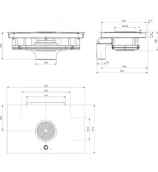
Main dimensions 830 x 515 x 198 mm
Weight (incl. accessories/packaging) Approx. 25 kg
Cooktop
Front cooking zones 205 x 230 mm 2100 W
power setting 3700 W
Rear cooking zones 205 x 230 mm 2100 W
power setting 3700 W
Power levels 1–9, power setting
Cooktop energy consumption
Cooking zone 1 176.5 (Wh/kg)
Cooking zone 2 172.2 (Wh/kg)
Cooking zone 3 177.2 (Wh/kg)
Cooking zone 4 175.9 (Wh/kg)
Total (average) 175.5 (Wh/kg)
Extraction system (BFIA)
Maximum flow volume 697.3 m
3
/h
Maximum static pressure 372 Pa
Power control 1-9, power setting
Exhaust air connection (BFIA) 222 x 40 x 89 mm
Recirculation system (BFIU)
Maximum flow volume 658.8 m
3
/h
Maximum static pressure 375 Pa
Power control 1–9, power setting
Recirculation connection (BFIU) 650 x 90 mm
Recirculation filter
Filter area 2 x 0,4 m
2
Filter capacity 150 operating hours
Service life 1 year
Tab. 3.1 Technical data
EN
13
Energy label
www.bora.com
4 Energy label
Product description
Glass ceramic cooktop with 4 cooking zones and an integrated
cooktop extractor
BFIA BFIU
Operating mode
Exhaust air Recirculation
Energy consumption
Value Value EN standard
Annual energy consumption (AEC
hood
) 54,8 kW/a 51,9 kW/a 61591
Energy efficiency class
B * 61591
Flow volume
Fluid dynamic efficiency (FDE
hood
) 23.1 21.0 61591
Fluid dynamic efficiency class
B * 61591
Lighting
Lighting efficiency (LE
hood
) * lx/Watt * lx/Watt *
Lighting efficiency class
* * *
Grease filtering
Level 9 maximum (GFE
hood
) 91 % 91 % 61591
Class level 9 normal
B * 61591
Grease filtering (additional details)
Level P maximum (GFE
hood
) 93 % 93 % 61591
Class level P maximum
B * 61591
Flow volume
Air flow level 1 minimum
194.8 m³/h * m³/h 61591
Air flow level 9 normal
607.3 m³/h * m³/h 61591
Air flow level P maximum (Q
max
) 697.3 m³/h 658.8 m³/h 61591
Sound power level
Level 1 minimum
40 dB(A) 39 dB(A) 60704-2-13
Level 9 normal
66 dB(A) 67 dB(A) 60704-2-13
Level P maximum
70 dB(A) 70 dB(A) 60704-2-13
Sound pressure level (additional details)
Level 1 minimum
27 dB(A) 26 dB(A) **
Level 9 normal
54 dB(A) 54 dB(A) **
Level P maximum
57 dB(A) 57 dB(A) **
Details according to 66/2014
Power consumption in off mode (P
O
) < 0.5 W < 0.5 W 61591
Time increase factor
1.2 1.2 61591
Energy efficiency index (EEI
hood
) 65.2 64.5 61591
Air flow rate at the best efficiency point (Q
BEP
) 382 m³/h 311.4 m³/h 61591
Pressure at the best efficiency point (P
BEP
) 272 Pa 288 Pa 61591
Electric power input at the best efficiency point (W
BEP
) 125 W 118.5 W 61591
Tab. 4.1 Energy label information
(The recirculation information is optional and not subject to mandatory inclusion on the label)
* This specification is not applicable for this product.
** The sound pressure level has been determined from a distance of 1 m (distance-dependent level recording) on the
basis of the sound power level established in EN 60704-2-13.
EN
14
Device description
www.bora.com
5 Device description
Observe all safety and warning information during
operation (see the Safety chapter).
The cooktop with cooktop extractor has the following
features:
Cooktop:
Automatic heat up function
Safety shut-down
Bridging function
Electronic power control (9 power levels)
Childproofing feature
Pause function
power setting
Residual heat display
Timer functions
Pan size recognition
Heat retention levels
Cooktop extractor:
Freely adjustable power control
Automatic cooktop extractor function
Automatic after-run
Safety shut-down
Filter service display
Interface communication
Depending on what you opted for when purchasing, the
cooktop extractor can be operated as an exhaust air or an
recirculating air version.
Exhaust mode
The air extracted from the cooktop is cleaned by the
stainless steel grease filter and released outside through
a duct system.
The exhaust air must not be expelled into:
a smoke or exhaust gas flue that is in operation;
a shaft used for the aeration of rooms where
fireplaces are installed.
If the exhaust air is to be directed into a smoke or exhaust
gas flue that is not in use, the installation must be checked
and approved by the responsible heating engineer.
Recirculation mode
The air suctioned away by the cooktop is purified by the
stainless steel grease filter and an activated charcoal filter
and fed back into the room in which the appliance is installed.
To prevent odours in the recirculated air, an activated
charcoal filter must be used. For hygiene and health
reasons, the activated charcoal filter must be replaced
at the recommended intervals (see the Cleaning and
maintenance section).
INFO In recirculation mode, ensure sufficient
ventilation and aeration to expel humidity.
The activated charcoal filter is equipped with an
integrated fine filter. The filter in the activated charcoal
filter is made from special activated charcoal, which is
ideal for trapping cooking odours.
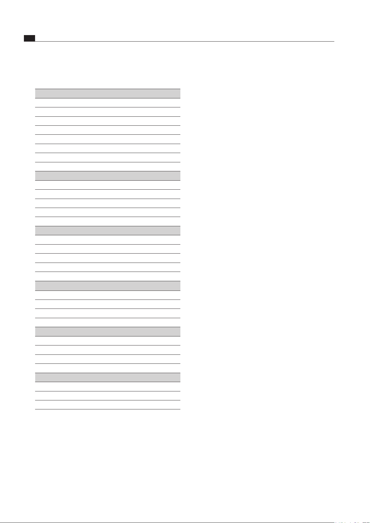
5.1 Structure
2
1
4
3
5
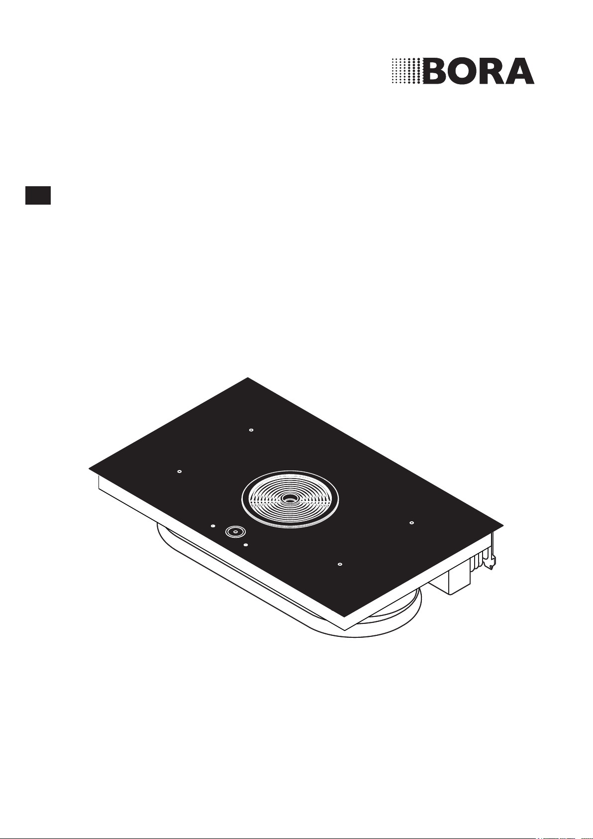
Abb. 5.1 Cooktop
[1] Air inlet nozzle
[2] Stainless steel grease filter
[3] Cooktop
[4] Suction opening
[5] Operating panel
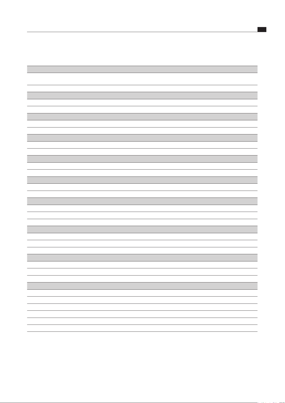
1
2
3
4
5
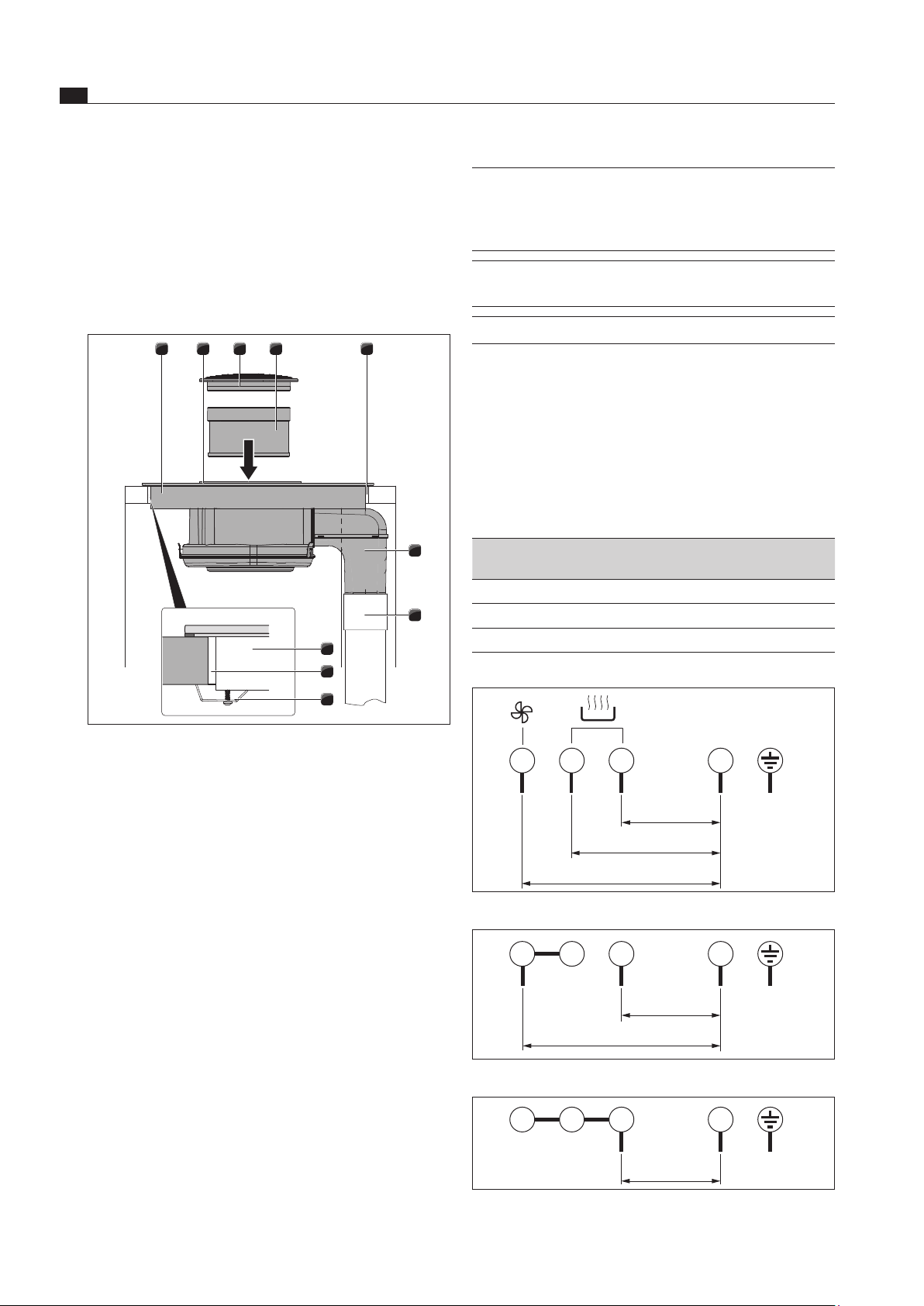
Abb. 5.2 Cooktop extractor – recirculation (BFIU)
[1] Flexible duct
[2] Activated charcoal filter housing
[3] Activated charcoal filter housing cover
[4] Activated charcoal filter
[5] Air guiding housing with housing base
EN
15
Device description
www.bora.com
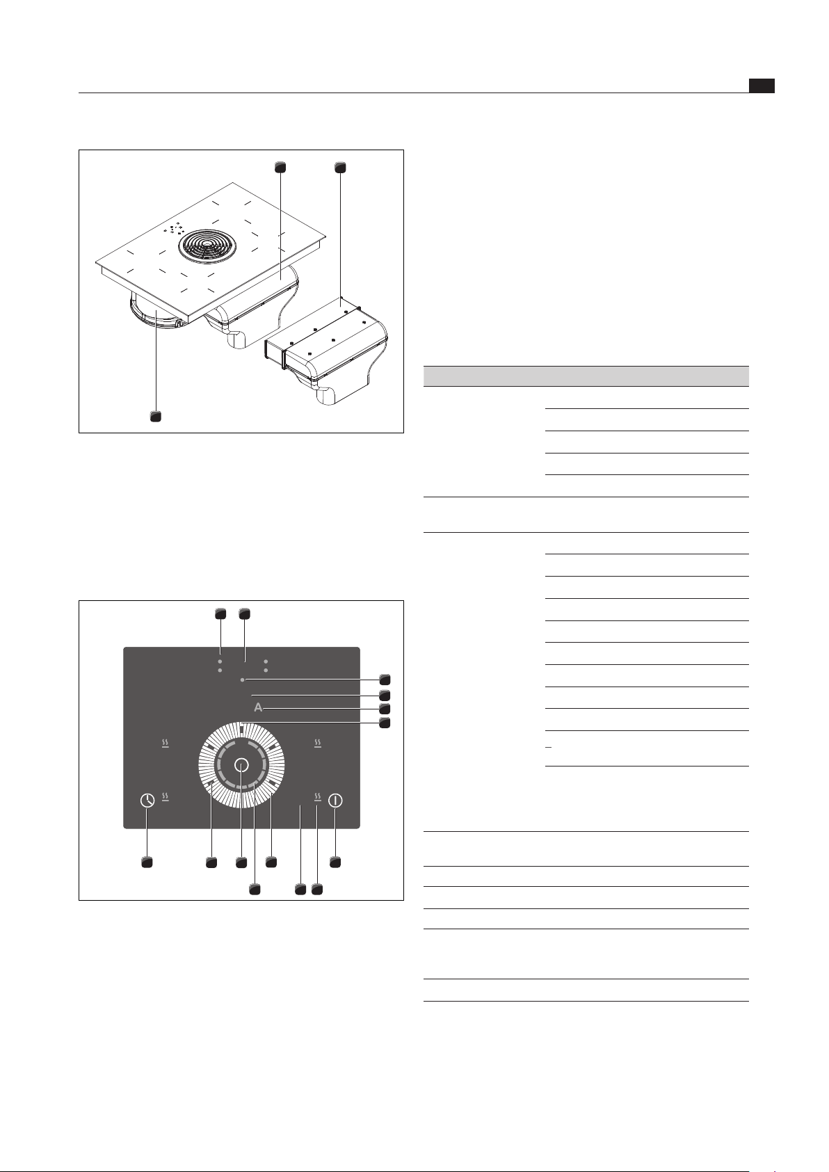
[4] Selecting the cooking zone
[4] Selecting the cooktop extractor
Display fields:
[6] Automatic cut-off timer control light
[7] Timer display
[8] Short-time timer control light
[9] Fan display/filter service display
[10] Automatic cooktop extractor display
[11] Heat retention level display
[12] Cooking zone indicator
[13] Power display
Display field Display Meaning
Fan display
0
Fan off
1 -
9
Power level
P
Power setting
n
Automatic after-run
F
Filter service display
Automatic cooktop
extractor function
A Active
Cooking zone
indicator
1 -
9
Power level
P
Power setting
A
Automatic heat up function
L
Childproofing feature
%
Bridging function
I I
Break
-
Heat retention level 42°C
:
Heat retention level 74°C
*
Heat retention level 94°C
v
No cookware or
cookware is too small.
H
Residual heat display:
Cooking zone is
switched off but still hot
(temperature > 60°C)
Heat retention level
display
On Active
Timer control light On Active
Flashes
Timer on (
00
); no time set
Off Timer off
Timer display
0 1 -
99
Set minutes for short time
(egg timer) or automatic
cut-off
00
Timer on; no time set
Tab. 5.1 Meaning of displays
Touch control
The operating panel is fitted with electronic sensor buttons,
a setting field and display panels. The sensor buttons
respond to finger contact.
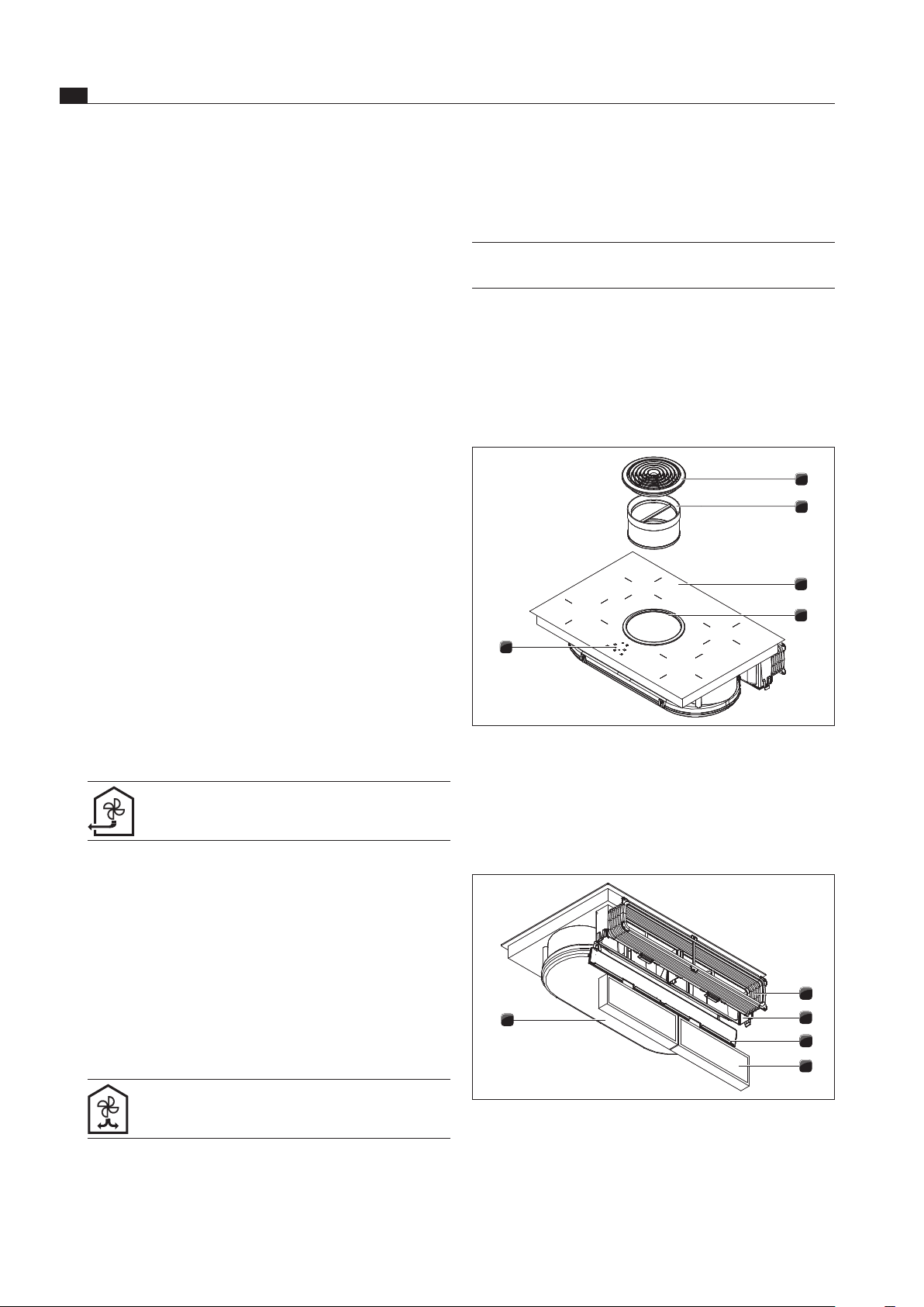
1
2
3
Abb. 5.3 Cooktop extractor – exhaust air (BFIA)
[1] Exhaust air arc with duct connection
[2] Horizontal exhaust air extension
[3] Air guiding housing with housing base
5.2 Operating panel and
operating principle
7
13
5
2
4
1
12 11
3
6
9
8
10
4
Abb. 5.4 Operating panel
Sensor buttons:
[1] Switching the cooktop/cooktop extractor on/off
[3] Multi-function button
[5] Activating the timer
[5] Setting the timer value (+10 min)
Setting ring:
[2] Adjusting the power level
[2] Setting the timer value (minutes)
[2] Locking/unlocking the childproofing feature
[2] Locking/unlocking the pause function
EN
16
Device description
www.bora.com
5.3.2 Automatic heat up function
The cooking zones are equipped with an automatic heat
up function that can be switched on and off.
The display shows
A
.
This function enables the cooking zone to work at full
power for a certain duration after switching on. After this
time, the power level is automatically switched back to
the power level set.
Automatic heat up function
Power level 1 2 3 4 5 6 7 8
Cooking
duration in
min./sec
0:48 2:24 3:50 5:12 6:48 2:00 2:48 3:36
Tab. 5.3 Overview of the automatic heat up function
5.3.3 power setting
All cooking zones are equipped with a power-enhancing
power setting.
The power setting can be used in order to quickly heat up
large quantities of water. If the power setting is activated,
the cooking zones will run at extra high power. After
10 minutes, the cooking zone is automatically switched
to power level
9
.
If the bridging function is activated, the power setting
cannot be used.
If cooking zone overheating protection is activated, the
power setting cannot be activated. The display flashes for
3 seconds and then switches back.
INFO Never heat up oil, fat and the like at this power
setting. The bottom of the pan can overheat
due to the high power output.
5.3.4 Heat retention levels
The heat retention level keeps cooked foods warm at
different temperatures.
The heat retention level display is active and lit.
The heat retention level is shown in the cooking zone
indicator e.g. for level 2
:
.
The maximum duration for the warming function is
limited to 8 hours.
Heat retention level Temperature in °C
Level 1 42 °C
Level 2 74 °C
Level 3 94 °C
Tab. 5.4 Heat retention levels
5.3.5 Bridging function
The two side cooking zones can be operated as a
connected cooking zone at the same power level.
The display shows
%
.
The bridging function is suitable for heating food in a
roaster.
You operate the device by touching the corresponding
sensor button with your finger. Keep the finger pressed
on the sensor button until you either hear an acoustic
signal or the display changes accordingly.
5.3 Functional principle of the
cooking zone
An induction coil is located underneath an induction
cooking zone. If the cooking zone is switched on, this coil
creates a magnetic field that acts directly on the base of
the pot thus heating it up. The cooking zone is only
indirectly heated up by the heat emitted by the pot.
Cooking zones with induction only work if the cookware
has a magnetisable base.
The induction automatically takes into account the size
of the cookware used so that only the area in the cooking
zone covered by the base of the pot is heated up.
Observe the minimum pot base diameter.
The cooking zone does not work
if it is switched on without cookware or with
unsuitable cookware;
if the base diameter of the cookware is too small;
if the cookware is removed from a switched on
cooking zone.
A
v
will appear in the cooking zone indicator if cookware
that is unsuitable or too small is used.
5.3.1 Power levels
The high power output of induction cooktops results in
the very quick heating up of cookware. A slight adjust-
ment is needed in comparison to conventional cooking
systems when selecting the power level in order to avoid
burning food.
Activity Power level
Melting of butter and chocolate, breaking up gelatine 1
Keeping sauces and soups warm, soaking rice 1-3
Cooking potatoes, pasta, soups, ragouts, steaming
fruit, vegetables and fish, defrosting food
2-6
Frying in coated pans, moderate frying (without
overheating the fat) of pork cutlets, fish
6-7
Heating up fat, browning fish, cooking thickened
sources and soups, making omelettes
7-8
Cooking large quantities of liquid, browning steaks 9
Heating up water P
Tab. 5.2 Recommendations for power levels
The specifications provided in the table are standard
values.
Depending on the cookware and filling quantity, it is
recommended to either decrease or increase the power
level.
EN
17
Device description
www.bora.com
Pay attention to the cookware bottom. The base of
the cookware should not show any sign of curvature.
Due to incorrect temperature monitoring of the hob
caused by the air gap between the cookware and the
temperature sensor underneath the hob, overheating
may occur. The bottom of the cookware must not have
any sharp grooves or sharp edges to avoid scratching
the cooktop.
Place the cookware (without a mat or similar) directly
onto the glass ceramic.
Noises
The following noises may occur in the cookware when
using induction cooking zones, depending on the material
and the finish of the base:
Humming may occur when using a high power level. It
decreases or disappears if the power level is decreased.
Crackling or whistling may occur due to the bases of
cookware made of different materials (e.g. sandwich
base).
Clicking sounds may occur during electronic switching
procedures especially at low power levels.
Whirring may occur when the cooling fan is switched
on. In order to increase the service life of the
electronic system, the cooktop is equipped with a
cooling fan. The cooling fan switches on automatically
if the cooktop is used intensively. You will hear a
whirring sound. The cooling fan may continue running
after the device has been switched off.
5.4 Functional principle of the
cooktop extractor
5.4.1 Freely adjustable power control
The power levels are controlled using the central setting
field on the operating panel.
5.4.2 Automatic cooktop extractor function
The automatic cooktop extractor function adjusts the
extraction performance (power level) to the highest
cooking zone cooking level used.
Function Power levels
Extractor level 4 4 4 4 5 6 7 8 9 P
Cooking level 1 2 3 4 5 6 7 8 9 P
Tab. 5.6 Extraction performance and cooking level
If the power level of the cooking zones is changed,
the automatic cooktop extractor function adjusts the
cooktop extractor performance after a 30 second
delay.
Once the cooking session is complete, the automatic
after-run is activated.
5.3.6 Pause function
The cooking session can be temporarily interrupted.
I I
appears in the display.
The cooking session and set timer are interrupted
while the pause function is active.
The pause function is limited to a maximum duration of
10 minutes.
5.3.7 Timer functions
You can use 2 timer functions:
Short-time timer (egg timer), no automatic switching
off of a cooking zone.
Automatic cut-off for automatically switching off a
cooking zone.
5.3.8 Pan size recognition
The cooking zone does not work
if
v
is shown in the display;
if it is switched on without cookware or with
unsuitable cookware;
if the base diameter of the cookware is too small;
if the cookware is removed from a switched on
cooking zone.
After 10 minutes have passed without a pan being
detected, the cooking zone will switch off automatically.
5.3.9 Suitable cookware
INFO The heating and heat through time for the base
of the cookware as well as the cooking results
are significantly influenced by the structure and
material of the cookware.
Cookware with this symbol is suitable for
induction cooktops.
The cookware used for the induction cooktop
must be made of metal, feature magnetic
properties and possess a sufficient bottom
surface.
Suitable cookware is made of:
stainless steel with a magnetisable base
enamelled steel
cast iron
Cooking zone Minimum diameter
Front 120 mm
Back 120 mm
Tab. 5.5 Minimum cookware diameter
Perform a magnet test, if necessary. If a magnet sticks
to the base of the utensils, they are normally induction
compatible.
EN
18
Device description
www.bora.com
Heat retention level Power level Switch off after hours
1 8.0
2 8.0
3 8.0
1 8.4
2 6.4
3 5.2
4 4.2
5 3.3
6 2.2
7 2.2
8 1.5
9 1.3
P 0.2
Tab. 5.7 Overview of the safety shut-down
Switch the cooking zone back on (see Operating control)
if you want to put the cooking zone back into operation.
Cooktop extractor
The cooktop extractor switches off automatically if no
buttons are pressed for 120 minutes.
5.5.3 Cooking zone overheating protection
All induction coils plus the cooling elements of the
electronics are equipped with overheating protection.
Before the induction coils and/or cooling elements
overheat, the overheating protection will initiate one of
the following measures:
The power setting
P
is automatically switched to power
level
9
after 10 minutes. The cooking zone indicator
P
switches to
9
.
The set power level is reduced.
The cooking zones switch off automatically.
H
(residual heat display) is displayed in the cooking
zone indicator if the cooking zone is still hot.
5.5.4 Automatic switch-off if the button is
pressed and held
The cooktop will be switched off automatically when
one or more sensor buttons are touched for longer than
10 seconds (finger contact, objects, soiling).
After a few seconds, the cooktop will switch off.
Remove the finger or object from the cooktop.
Clean the cooktop as required.
Where necessary, switch the cooktop back on.
5.5.5 Childproofing feature
The childproong feature prevents the cooktop from
being switched on accidentally. The childproong feature
can only be activated when the cooktop is switched on
and all cooking zones are switched o (see the Operation
chapter).
5.4.3 Power setting
The cooktop extractor has a power-enhancing power
setting.
This power setting makes it possible to suction away high
levels of cooking vapours more quickly. After 10 minutes,
the power setting is automatically switched to power level
9
.
5.4.4 Automatic after-run
The cooktop extractor continues to run at a lower level
n
and switches off automatically after 20 minutes.
5.4.5 Filter service display
The filter service display becomes active after the cooktop
extractor has operated for 150 hours. The activated
charcoal filters have reached the end of their service life
(with recirculation only) and the stainless steel grease
filter needs to be thoroughly cleaned.
A flashing
F
is displayed in the filter service display.
5.4.6 Interface communication
The internal interface can be used for extended control
options. This has a Home-In and a Home-Out contact
(see Installation chapter).
The Home-In contact can be used for the incoming
signal from external switch devices (e.g. window
contact switch).
The Home-Out contact can be used to control
external installations.
5.5 Safety devices
5.5.1 Residual heat display
INFO While
H
is displayed in the cooking zone
indicator (residual heat display), do not touch
the cooking zone or place any heat-sensitive
objects on top of it. Risk of burns and fire!
After switching it off, the cooking zone remains hot.
H
is displayed in the cooking zone indicator (residual heat
display). The cooking zone indicator will go out after
sufficient cooling time (temperature < 60°C).
5.5.2 Safety shut-down
Cooking zone
Each cooking zone is switched off automatically when the
cooking zone exceeds the maximum operating duration at
a power level.
H
(residual heat display) is then displayed in
the cooking zone indicator.
EN
19
Installation
www.bora.com
6 Installation
Observe all safety and warning information (see the
Safety chapter).
Follow the enclosed manufacturer‘s information.
INFO The power supply cable must be provided by
the customer.
INFO The device must not be installed above cooling
devices, dishwashers, stoves, ovens, washing
machines or dryers.
INFO The contact surfaces of the worktops and wall
sealing strips must be made of a heat-resistant
material (up to approx. 100°C).
INFO Worktop cut-outs must be moisture-sealed
using suitable means and, where necessary,
fitted with a thermal insulator.
6.1 Checking the scope of delivery
Name Quantity
Surface induction glass ceramic cooktop with
cooktop extractor
1
Stainless steel grease filter 1
BAKF activated charcoal filter 2
Flexible duct (BFIU only) 1
EURO screws (BFIU only) 6
BLAVH horizontal exhaust air extension (BFIA only) 1
Mounting straps 5
Sealing tape 1
Glass ceramic scraper 1
Cable routing clips 3
Protective hose 2
Cable tie 2
Operating and installation instructions 1
Lenshead screw 5
Drilling template (BFIU only) 1
Height adjustment plate set 2
Tab. 6.1 Scope of delivery
Check the scope of delivery for damage and make sure
it is complete.
If there are any missing or damaged parts, please
notify BORA After Sales Service immediately.
Do not under any circumstances install parts which are
damaged.
Dispose of transport packaging in the proper manner
(see the Decommissioning, Disassembly and Disposal
chapter).
6.2 Tool and aids
The following tools are required for the correct installation
of the cooktop:
Pencil
Standard or cordless drill with a 5 mm wood drill
(for the rear wall)
Compass saw or hand saw
Drilling template for cut-out on rear wall
(included in scope of delivery)
Phillips screwdriver Z2
Silicone sealant for sealing cutting surfaces
6.3 Assembly instructions
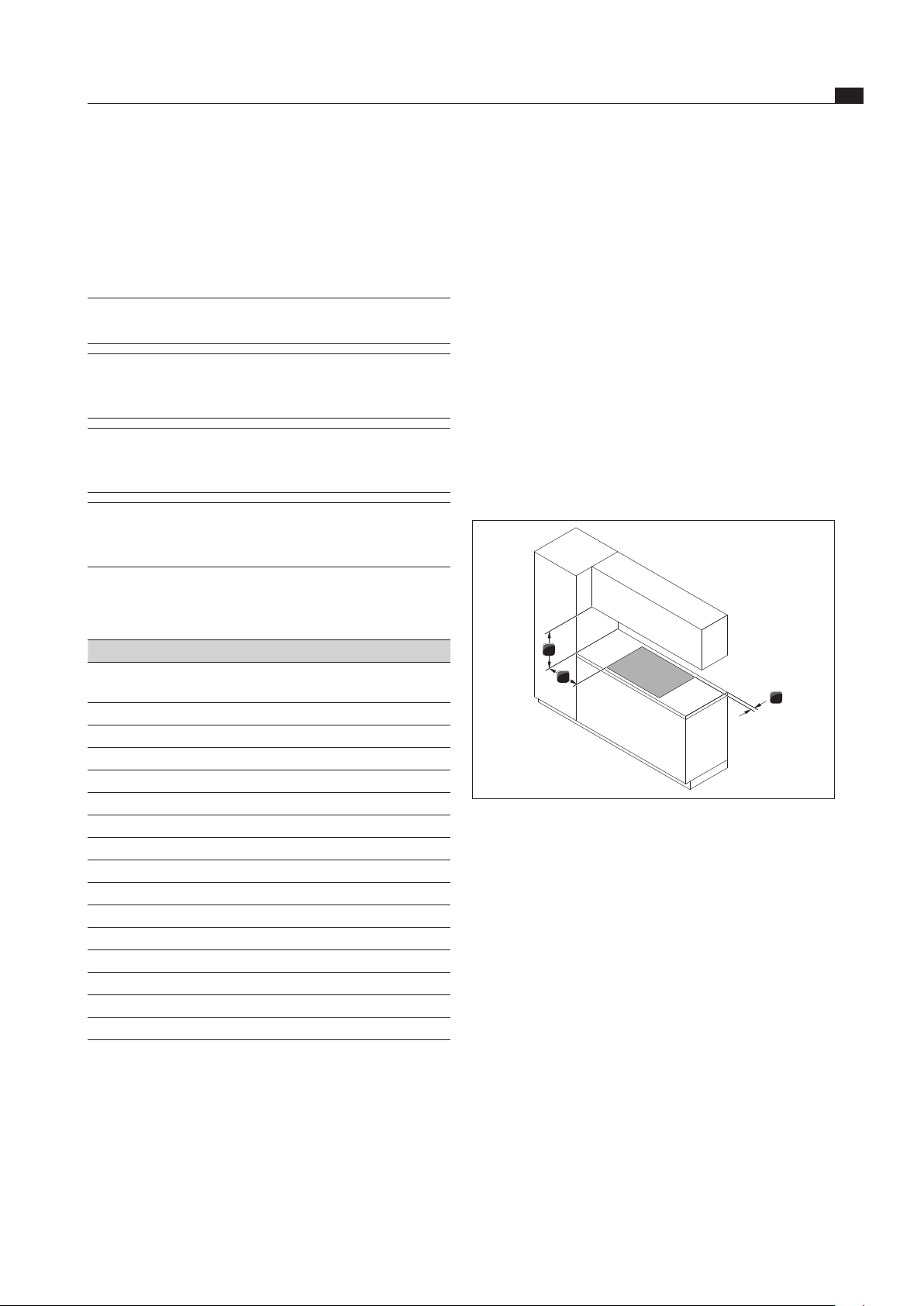
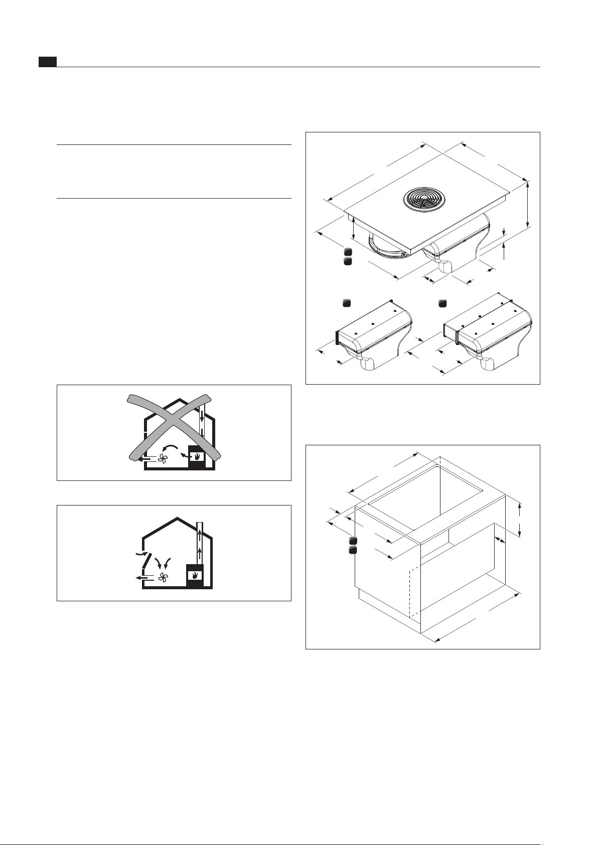
6.3.1 Safety distances
Maintain the following safety distances:
1
3
2
Abb. 6.1 Recommended minimum clearances
[1] Rear minimum clearance of 50 mm between the worktop
cut-out and the rear corner of the worktop.
[2] Minimum clearance of 300 mm from the left and right of the
worktop cut-out to the adjacent cabinet or wall.
[3] Minimum clearance of 600 mm between the worktop
and the wall unit. A minimum clearance of 1000 mm is
recommended for ergonomic reasons.
6.4 Cut-out dimensions for the
cooktop
Preparing the worktop
Create the worktop cut-out taking into account the
specified cut-out dimensions.
Make sure that the cutting surfaces of the worktops
are properly sealed.
Comply with the instructions of the worktop
manufacturer.
EN
20
Installation
www.bora.com
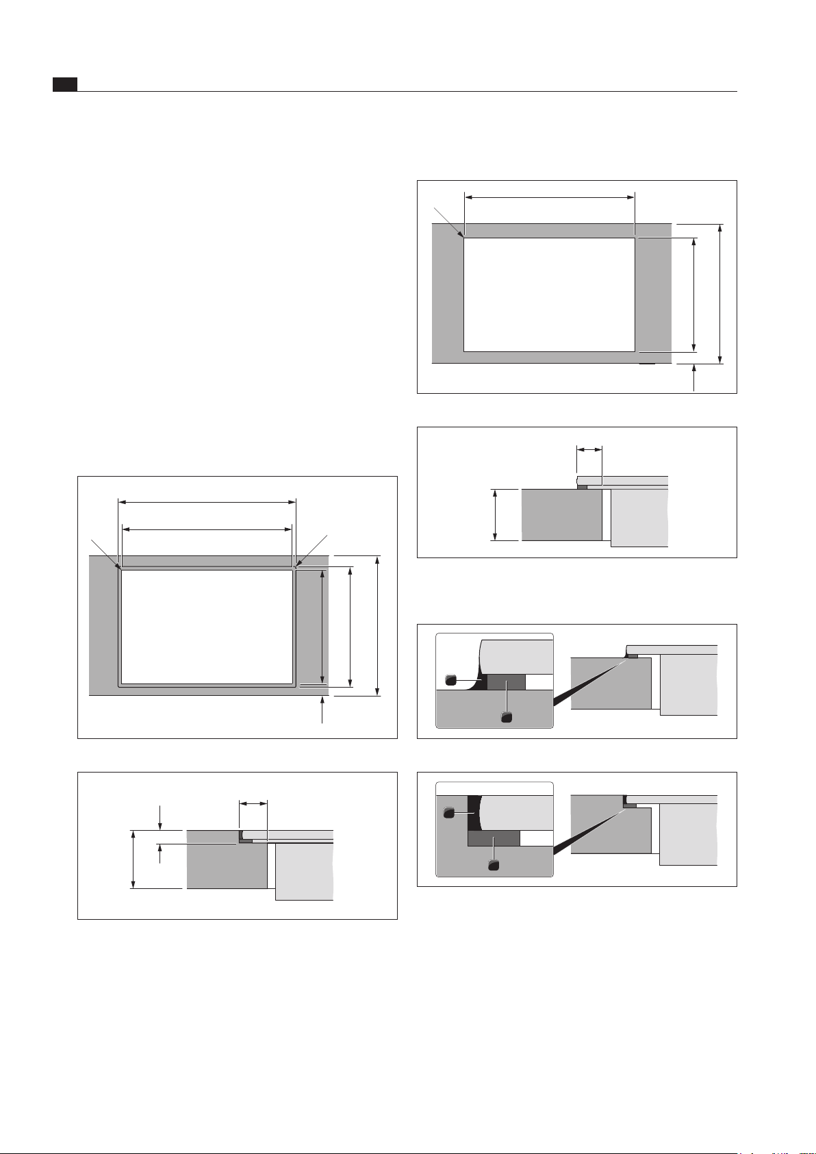
Surface mounting
805
<R5
50 490
600
Abb. 6.4 Cut-out dimensions for surface mounting
12,5
10 ... 50
Abb. 6.5 Dimension of support for surface mounting
Attaching the sealing tape
2
1
Abb. 6.6 Sealing tape with surface mounting
1
2
Abb. 6.7 Sealing tape, ush installation
[1] Black heat-resistant silicone sealing compound
[2] Sealing tape
With surface mounting, attach the enclosed sealing
tape [2] to the underside of the cooktop before
installing it. Do not leave any gaps.
With flush installation, attach the enclosed sealing tape
[2] to the horizontal cutting edge in the worktop cut-out,
even if you are sealing the cooktop with a silicone
sealing compound [1] or similar.
Precisely align the cooktop.
Cross bars on the kitchen unit in the area of the
worktop cut-out may need to be removed.
No false floor is necessary below the cooktop with
cooktop extractor.
Make sure that the area below the device is sufficiently
ventilated.
An opening cross-section of > 50 cm
2
must be available
at the front and in the false floor for the ventilation of
the cooktop’s induction equipment.
The drawers and/or shelves in the floor unit must be
removable.
A return flow aperture > 500 cm
2
is required in the
kitchen units for recirculation appliances (e.g. by
shortening the plinth boards or using suitable slatted
plinths).
The power socket is located at the bottom of the front
of the device.
Flush installation
834
805
519
R5
<R5
50 490
600
Abb. 6.2 Cut-out dimensions for ush installation
6,5
14,5
10 ... 50
Abb. 6.3 Dimension of groove for ush installation
EN
21
Installation
www.bora.com
805
510 - 570
>900
650
>50
119
>25
90
490
>600
90
117
650
675
< R15
133
119
6x Ø5mm
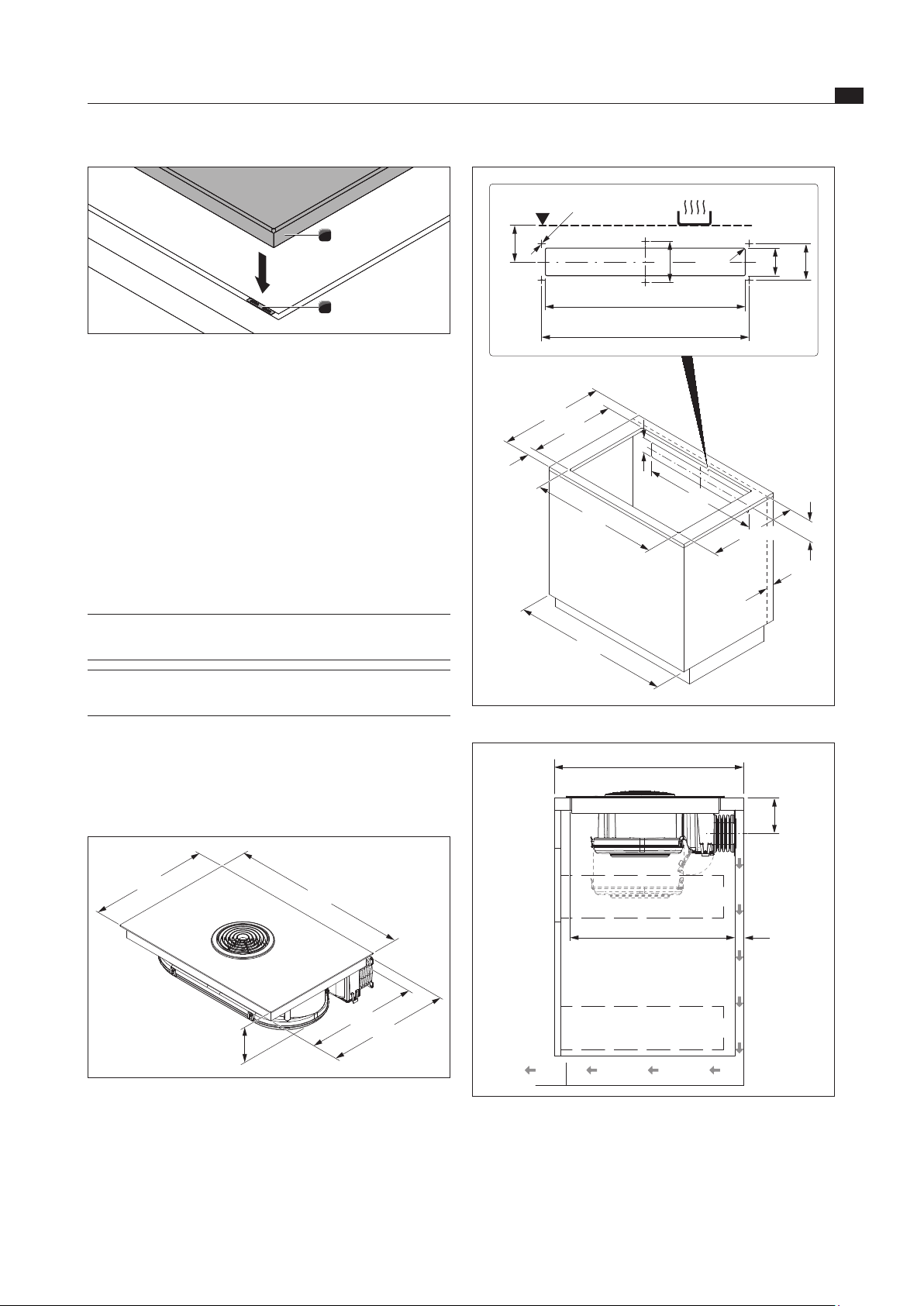
Abb. 6.10 Furniture dimensions for recirculation
> 25
510 - 570
119
> 600
Abb. 6.11 Installation dimensions for recirculation, depth of
worktop 600 mm
The floor unit must have a continuous back wall so
that the recirculation air is not directed into the front
furniture body compartment.
There must be a cut-out in the back wall.
1
2
Abb. 6.8 Height adjustment plates
[1] Cooktop
[2] Height adjustment plate
If applicable, insert the height adjustment plate [2].
Note down the type designation and build number of
the cooktop (FD number) on the back of this manual.
Both details can be found on the nameplate on the
underside of the cooktop.
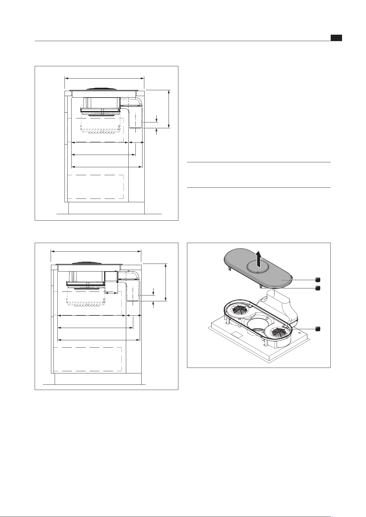
6.5 Installing the recirculation
version (BFIU)
INFO A minimum clearance of 25 mm must be
provided for the vertical return flow aperture.
INFO A return flow aperture of at least 500 cm
2
must
be provided.
If the cooktop extractor is used exclusively in recirculation
mode, operation with an open fireplace is possible without
any additional safety measures.
Installation dimensions
198
483
830
515
510 - 570
Abb. 6.9 Device dimensions for recirculation
EN
22
Installation
www.bora.com
Use a screwdriver (not an electric screwdriver) to
screw the flexible duct to the back wall of the kitchen
unit until it is hand-tight.
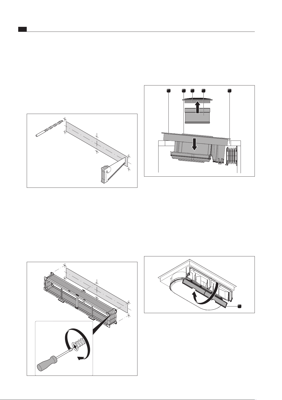
Inserting the cooktop
54321
Abb. 6.14 Insert the cooktop obliquely
[1] Cooktop
[2] Suction opening
[3] Air inlet nozzle
[4] Stainless steel grease filter
[5] Worktop cut-out
Before inserting the cooktop, remove the air inlet
nozzle [3] and the stainless steel grease filter [4].
Use the suction opening as a handle during insertion.
Insert the cooktop obliquely into the worktop cut-out
[5].
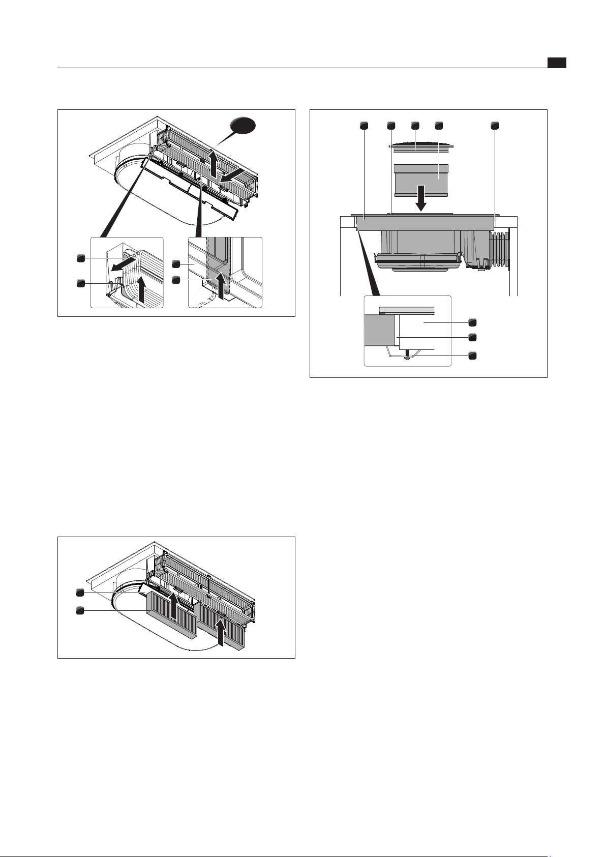
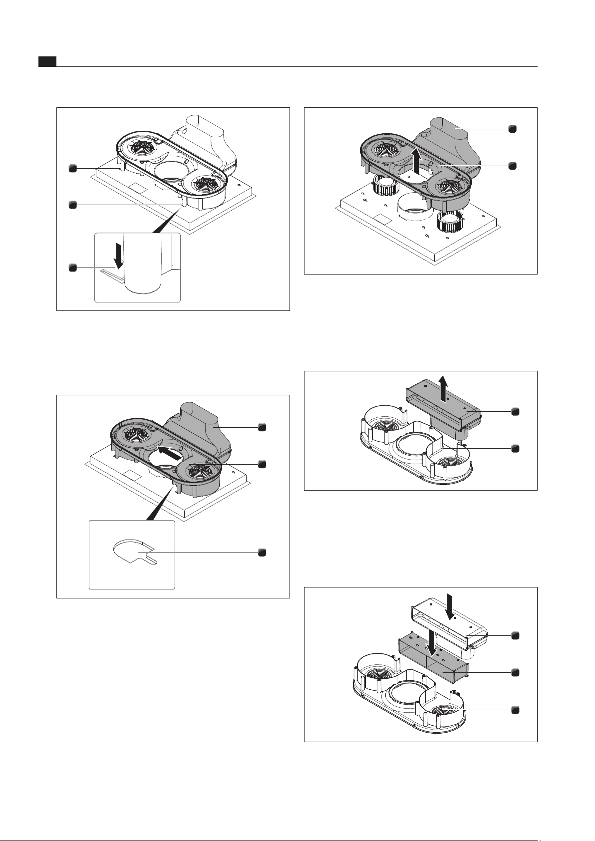
1
Abb. 6.15 Opening the housing cover
[1] Housing cover of the activated charcoal filter
Open the housing cover of the activated charcoal filter
[1] from below.
A minimum clearance of 25 mm between the back
furniture body wall and an adjacent kitchen unit or room
wall must be observed for the return flow aperture.
Preparing the back wall of the kitchen unit
Adjust the back wall according to the required
installation dimensions.
If applicable, move the back wall.
If necessary, extend the height of the back wall so that
the unit is closed to the front.
6 x ø5
Abb. 6.12 Cut-out and connection requirements
In the middle of the cooktop, use the drilling template
provided to mark the return flow aperture and
the connection drill holes in accordance with the
installation dimensions.
Saw out the return flow aperture.
Drill the connection drill holes.
Decrease the height of the skirting boards or create
corresponding openings in the plinth.
Screwing on the flexible duct
Abb. 6.13 Flexible duct with 6 EURO screws 6.3 x 10 mm
EN
23
Installation
www.bora.com
54321
6
5
1
Abb. 6.18 Securing the cooktop in the middle
[1] Cooktop
[2] Suction opening
[3] Air inlet nozzle
[4] Stainless steel grease filter
[5] Worktop cut-out
[6] Mounting bracket
For surface mounting
Make sure that the sealing tape for the cooktop is flat
against the worktop.
For flush installation
Make sure that the sealing tape of the cooktop is
sealed well all the way round.
If applicable, insert the height adjustment plate.
Fasten the cooktop to the worktop using the mounting
brackets [6].
Next, insert the stainless steel grease filter [4] and the
air inlet nozzle [3].
Seal the surrounding gap with black, heat-resistant
silicone sealant.
click
1
4
3
2
Abb. 6.16 Mounting the frame of the exible duct
[1] Retaining groove of the housing of the activated charcoal
filter
[2] Position shackles
[3] Flexible duct frame
[4] Lower lock
Insert the frame of the flexible duct into the retaining
groove on the housing of the activated charcoal filter
[1].
Ensure that both lateral position shackles [2] are in the
guide.
Slide the frame upward [3] until the lower [4] and
upper lock engage in the middle.
Ensure that the frame is inserted into the housing
groove [1] all round.
1
2
Abb. 6.17 Inserting the activated charcoal lter
[1] Housing cover of the activated charcoal filter
[2] Activated charcoal filter
Remove the packaging from the activated charcoal
filters.
Insert the two activated charcoal filters [2] from below.
Check the direction of flow of the filters.
This is identified by an arrow.
Close the housing cover [1].
EN
24
Installation
www.bora.com
Installation dimensions
b
b
a
a
170
270
100
170
830
535
198
635
515
40
222
89
290
Abb. 6.21 Device dimensions with exhaust air
[a] Device dimensions without cable extension
[b] Device dimensions with cable extension
805
490
>50
>900
320
110
b
a
600
700
Abb. 6.22 Kitchen unit dimensions with exhaust air
[a] Worktop depth from 600 mm
[b] Worktop depth from 700 mm
6.6 Installing the exhaust air version
(BFIA)
INFO The state and regional laws and regulations
must be observed with regard to the exhaust
duct design. A sufficient air supply must be
ensured.
6.6.1 Operating the cooktop extractor with
a fireplace that depends on the air in
the room
Fireplaces that depend on the air in the room (e.g. gas,
oil, wood or coal-fired heaters, continuous-flow water
heaters, instantaneous water heaters) draw in air from
the room in which they are installed and release the
exhaust fumes into the outside air via an exhaust system
(e.g. chimney).
If the cooktop extractor is used in exhaust mode, it draws
in air from the room in which it is installed as well as from
neighbouring rooms. If there is insufficient air supply, low
pressure will occur. Toxic gases could be drawn out of the
chimney or extraction ducting and back into the room.
Abb. 6.19 Exhaust air installation – not permitted
Abb. 6.20 Exhaust air installation – correct
If simultaneously operating both a fireplace and the
cooktop extractor in the same room, ensure that:
the maximum low pressure is 4 Pa (4 x 10⁻⁵ bar);
a safety device (e.g. window contact switch, low
pressure warning device) is used to ensure that a
sufficient supply of fresh air is guaranteed;
the exhaust air is not be ducted into a chimney that
is used for exhaust gases of devices operated with
gas or other combustibles;
the installation is checked and approved by an
authorised certified engineer (e.g. heating engineer).
EN
25
Installation
www.bora.com
The maximum exhaust air duct length is 6 m.
Planning instructions for the installation of the exhaust
air ducts are provided in the BORA ventilation handbook.
Preparing the back wall of the kitchen unit
Before installation, check the suitability of floor unit
with regard to the necessary installation dimensions
for the device and the planned duct system.
If necessary, adjust the position of the back wall
according to the required installation dimensions.
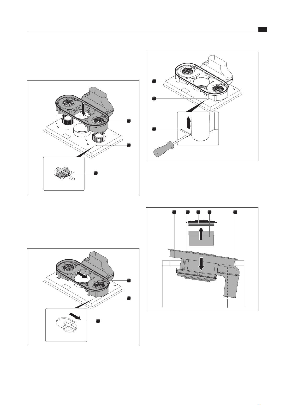
Extending the exhaust air duct
INFO The exhaust air duct can optionally be extended
by 100 mm to the rear using the supplied
horizontal extension BLAVH.
Remove the air inlet nozzle and the stainless steel
grease filter.
Insert the cooktop with the glass ceramic panel facing
downward on a clean and soft surface (e.g. cardboard,
packaging material) in order to avoid damage to the
glass ceramic panel.
3
2
1
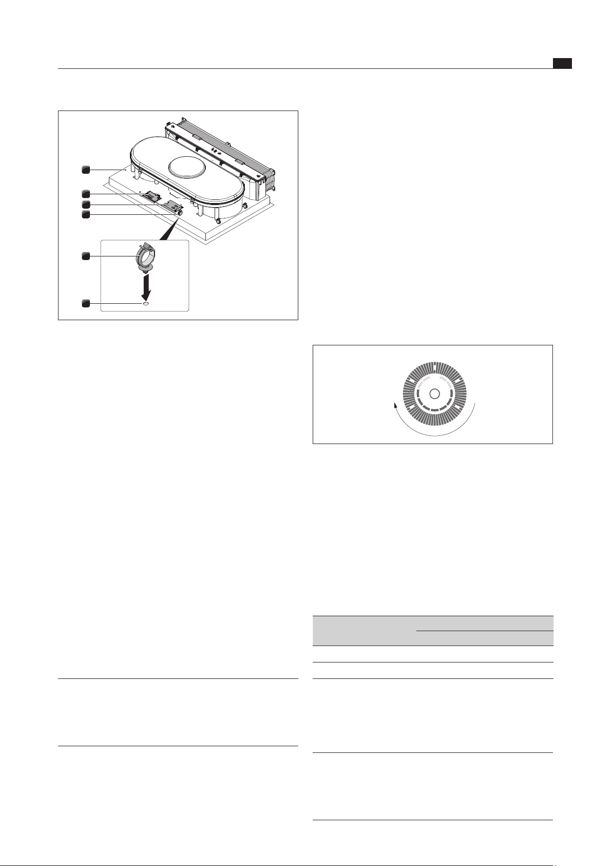
Abb. 6.25 Removing the housing base
[1] Housing base
[2] Locks
[3] Air guiding housing
Open the 4 locks [2].
Remove the housing base [1] from the air guiding
housing [3].
> 600
< 430
480
535
105
290
40
Abb. 6.23 Installation dimensions for exhaust air,
worktop depth 600 mm
> 700
< 530
580
635
105
290
40
100
Abb. 6.24 Installation dimensions for exhaust air,
worktop depth from 700 mm
Installation conditions
The back wall of the floor unit must be adjusted for the
exhaust air duct.
A minimum clearance of 110 mm between the back
furniture body wall and an adjacent kitchen unit or
room wall must be observed for the air duct.
The exhaust air must be directed to the outside in
appropriate exhaust air ducts.
The minimum cross-section of the air ducts must be
176 cm
2
. This corresponds to a round pipe with a
diameter of 150 mm.
EN
26
Installation
www.bora.com
2
1
Abb. 6.28 Removing the air guiding housing
[1] Exhaust air arc
[2] Air guiding housing
Remove the air guiding housing [2] with the exhaust air
arc [1] upward.
2
1
Abb. 6.29 Removing the exhaust air arc
[1] Exhaust air arc
[2] Air guiding housing
Remove the exhaust air arc [1] from the air guiding
housing [2] upward.
3
2
1
Abb. 6.30 Inserting the air duct extension
[1] Exhaust air arc
[2] Exhaust air duct extension
[3] Air guiding housing
1
1
1
Abb. 6.26 Unlocking the position lock
[1] Shackles for position lock
Use a screw driver to press the shackles left and right
[1] downward to unlock the position lock.
3
2
1
Abb. 6.27 Moving the air guiding housing
[1] Exhaust air arc
[2] Air guiding housing
[3] Insertion aperture
Move the air guiding housing [2] laterally together with
the exhaust air arc [1] to the left edge of the insertion
aperture [3].
EN
27
Installation
www.bora.com
1
1
1
Abb. 6.33 Position lock
[1] Shackles for transportation and position lock
Press the two shackles [1] for the position lock upward.
Raise the cooktop with integrated cooktop extractor.
Turn the glass ceramic side upward.
54321
Abb. 6.34 Inserting the cooktop
[1] Cooktop
[2] Suction opening
[3] Air inlet nozzle
[4] Stainless steel grease filter
[5] Worktop cut-out
Use the suction opening [2] as a handle during insertion.
Hold the suction opening [2].
Insert the cooktop in the middle of the worktop
cut-out [5].
Insert the exhaust air duct extension [2] into the
groove of the air guiding housing [3].
Insert the exhaust air arc [1] into the groove of the
exhaust air duct extension [2].
2
2
1
Abb. 6.31 Placing the airow assembly on the cooktop base
[1] Airflow assembly
[2] Openings
Position the airflow assembly [1] on the cooktop base
in such a way that all retaining hooks fit into the
openings [2].
2
2
1
Abb. 6.32 Engaging the airow assembly
[1] Airflow assembly
[2] Openings
Now move the airflow assembly [1] to the right until it
is fully engaged in the opening slot [2].
EN
28
Installation
www.bora.com
INFO The power connection may only be established
by certified specialists. He/she also assumes
responsibility for the proper installation and
commissioning.
INFO Connections via plug-in contacts (Schuko plugs)
are not permitted.
INFO The device complies with IEC 61000-3-12
Switch off the main switch/automatic circuit breaker
before connecting the cooktop.
Protect the main switch/automatic circuit breaker
from being switched on without permission.
Make sure the device is not energised.
Connect the cooktop exclusively via a fixed connection
to an H 05 VV-F power supply cable with corresponding
minimum cross-section (see tab. Fuse protection and
minimum cross-section).
Connection Fuse protection Minimum
crosssection
3-phase connection 3 x 16 A 2.5 mm
2
2-phase connection 2 x 16 A 2.5 mm
2
1-phase connection 1 x 32 A 4 mm
2
Tab. 6.2 Fuse protection and minimum cross-section
1
L1 L2
L3
2 3 4
N
PE
220 - 240 V~
220 - 240 V~
220 - 240 V~
Abb. 6.36 Connection diagram 3-phase connection
1
L1 L3
2 3 4
N
PE
220 - 240 V~
220 - 240 V~
Abb. 6.37 Connection diagram 2-phase connection
1
L1
2 3 4
N
PE
220 - 240 V~
Abb. 6.38 Connection diagram 1-phase connection
For surface mounting
Make sure that the sealing tape is resting on the
worktop.
For flush installation
Make sure that the sealing tape of the cooktop is
sealed well all the way round.
If applicable, insert the height adjustment plate.
54321
6
5
8
7
1
Abb. 6.35 Connect the air duct
[1] Mounting bracket
[1] Exhaust air arc
[2] Exhaust air duct
Connect the exhaust air duct [8] at the installation site
to the exhaust air arc [7].
Seal the duct connection so that it is airtight using
adhesive sealing tape UDB1.
Fasten the cooktop to the worktop using the mounting
brackets [6].
Next, insert the stainless steel grease filter [4] and the
air inlet nozzle [3].
Seal the surrounding gap with black, heat-resistant
silicone sealant.
6.7 Establishing the power connection
Observe all safety and warning information
(see the Safety chapter).
Observe all national and regional laws and regulations
as well as the supplementary regulations of the local
utility companies.
EN
29
Installation
www.bora.com
Programming the device power management
Prerequisites:
The cooktop is switched off.
All cooking zones are switched off.
Separate the device from the voltage supply using
the LS switch, fuses, automatic circuit breakers or
contactors.
After re-establishing the voltage supply, you have up to
two minutes to open the service menu.
Re-connect the appliance to the voltage supply.
Press and hold the multi-function button.
Briefly press the timer button.
A short signal tone will sound and the front half of the
setting ring lights up.
Now release the multi-function button.
Swipe the setting ring in a circular, clockwise motion
to move from 3 to 8.
0
38
Abb. 6.40 Opening the service menu
C0
is displayed intermittently with
C
and
O
on the left
front cooking zone indicator.
0
is displayed in the left back cooking zone indicator
(factory setting).
Use the multi-function button to select the menu level
C0
.
Press any button on the setting ring to change the
setting from
0
to
1
.
Press the timer button to save the change.
The cooktop is ready for use.
Menu setting
C0
Cooking zone power
Left side Right side
0
3.7 kW 3.7 kW
1
2.2 kW 2.2 kW
Tab. 6.3 Device power management
6.9 Connect the external switch
contact
INFO The Home-In and Home-Out communication
connection must only be connected by a
certified specialist. He/she also assumes
responsibility for the proper installation and
commissioning.
4
4
1
1
3
2
Abb. 6.39 Electrical connections of the cooktop
[1] Bore holes
[2] Power supply
[3] Connection control
[4] Cable mounting clip
Connect the power supply cable to the power supply [2]
of the cooktop with cooktopFig. 6.36r in accordance
with the relevant connection diagram (see fig. 6.36
Connection diagram).
For a 1-phase or 2-phase connection, connect the
relevant contacts with the BKAS connector clip
(in scope of delivery).
Fasten the cable mounting clips [3] to the designated
bore holes [1] either on the left or right hand side for
the cable routing to the rear.
Ensure that the cable is not caught or damaged and is
not able to touch any hot hobs.
Verify that the installation was done correctly.
Switch on the main switch/automatic circuit breaker.
Put the cooktop into operation (see the Operation
chapter).
Check all the functions are working correctly.
6.8 Device power management
(overall power reduction)
INFO The device power management function can be
set in the service menu. Accessing the service
menu and changing the power management
setting may only be performed by a certified
specialist.
The total device power can be reduced to 4.4 kW upon
initial commissioning if the required electrical power
cannot be provided at the installation site.
The connection must always be equipped with 20 A fuse
protection as a minimum.
EN
30
Installation
www.bora.com
X1.1
X2.1
X1.2
X1.4
X1.5
Home
In
Home
Out
Abb. 6.42 External switch contacts connection diagram
1
4
7
6
5
3
2
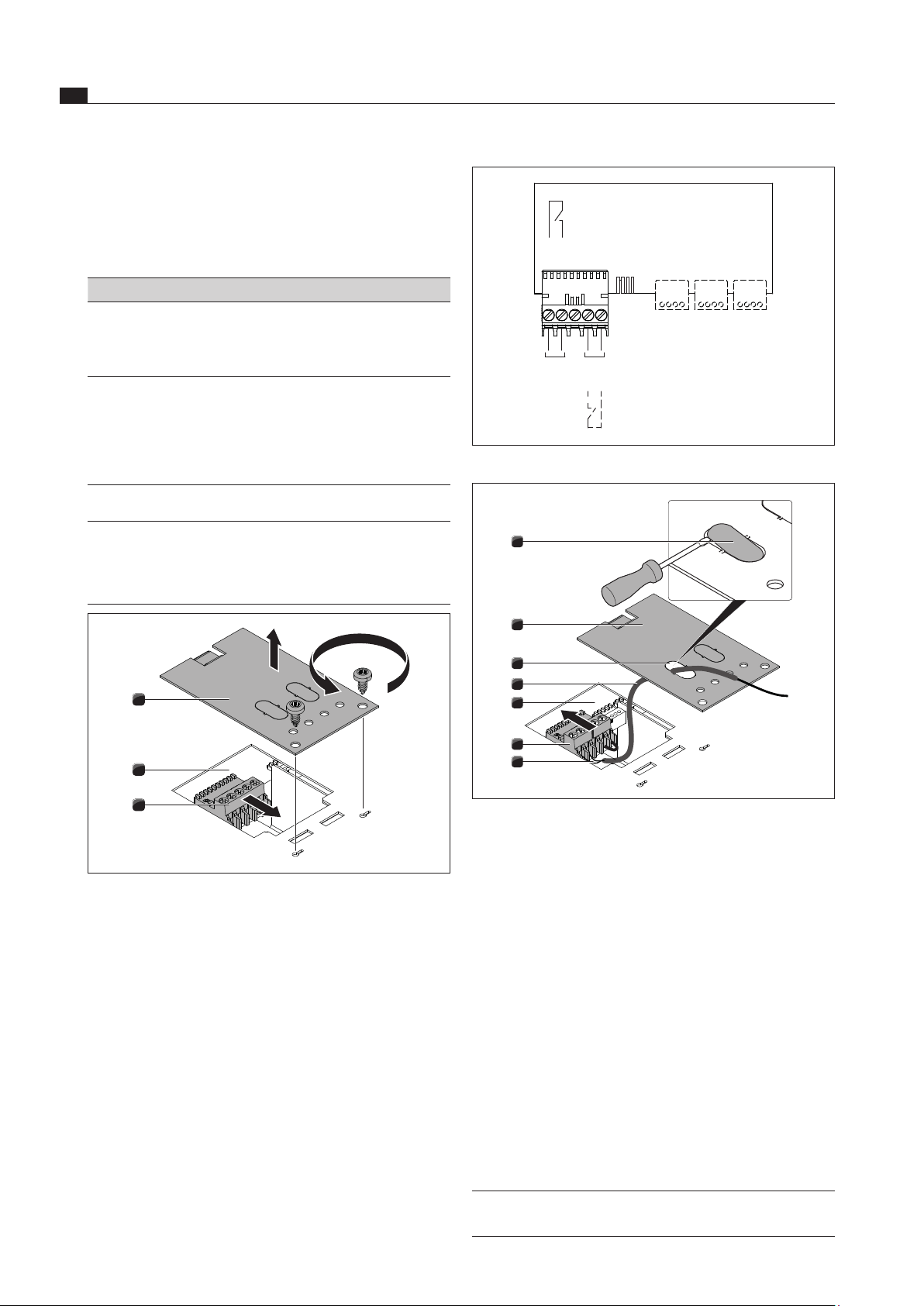
Abb. 6.43 Connecting the cable
[1] Sealing cover
[2] Cover
[3] Cable opening
[4] Protective hose
[5] Electronic unit
[6] Contact plug
[7] Cable connection
Remove the sealing cover [1] for the cable opening [3]
with a screw driver.
Move the protective hose [4] onto the cable [7].
Guide the cable [7] with the protective hose [4]
through the cable opening [3] in the cover.
Remove the installed bridge.
Connect the cable for the relevant contact to the
contact plug [6] in accordance with the relevant
connection diagram (see fig. Connection diagram for
external switch contacts).
INFO The Home-In contact must be bridged if this is
not used (bridged on delivery).
When using Home-In and Home-Out, you will require the
relevant documents for the external switching devices in
order to ensure safe device connection and operation.
The following switch connections can be used:
Contact Function Connection
Home-In Cooktop extractor on/off
connection for external switch
contact (contact closed:
cooktop extractor on)
30 V DC 0.7 mA
Home-Out Electrically isolated contact
for controlling external
installations depending on
the operation of the cooktop
extractor (cooktop extractor
on: contact closed)
Maximum 250V/4A
Tab. 6.4 Home-In and Home-Out switch connections
INFO The Home-In contact can be used for external
safety devices (e.g. window contact switches).
If the switch is open, the cooktop extractor is
out of operation.
3
2
1
Abb. 6.41 Opening the cover and disconnecting the contact plug
[1] Cover
[2] Electronic unit
[3] Contact plug
Open the cover [1].
Adhere to the connection diagram when connecting
Home-In and Home-Out.
Disconnect the contact plug [3] from the electronic
unit [2].
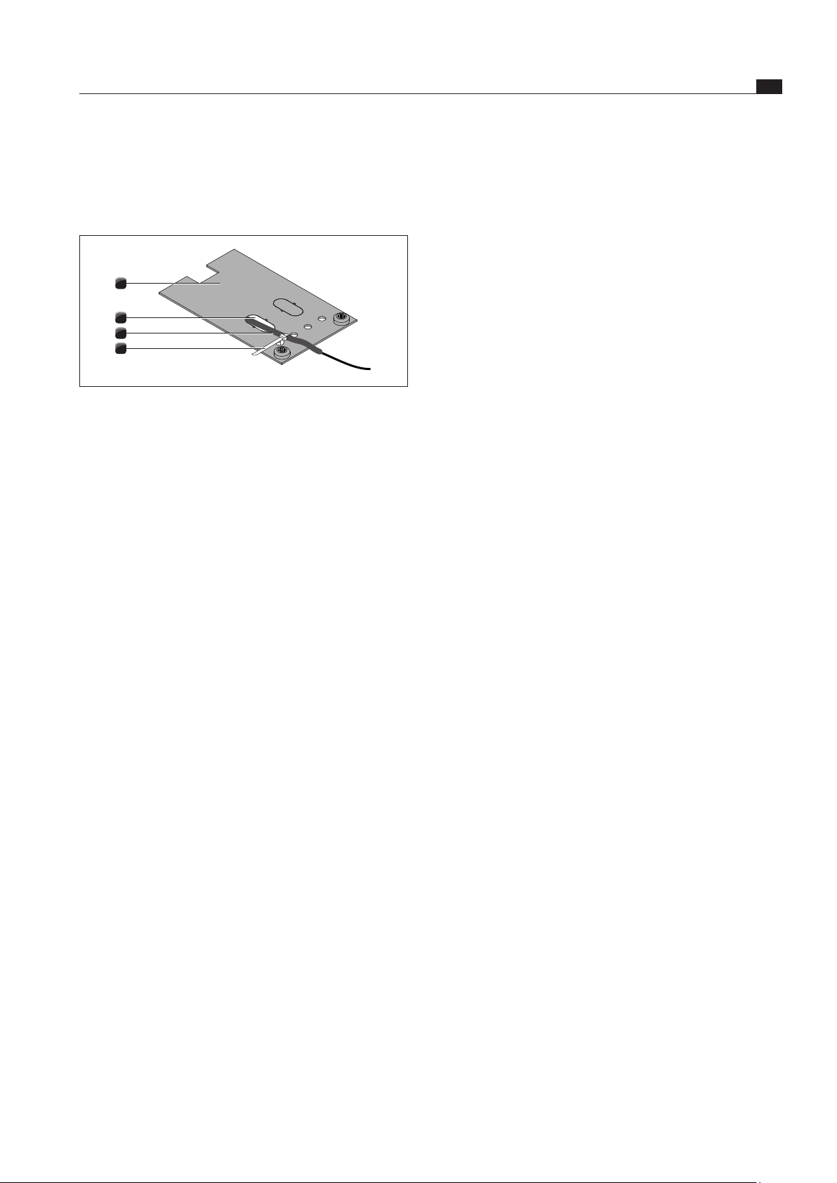
EN
31
Installation
www.bora.com
Connect the contact plug [6] to the electronic unit [5].
Ensure that the protective hose [4] is located directly
on the contact plug [6] and that the protective hose [4]
goes through the opening [3] in the cover [2].
4
3
2
1
Abb. 6.44 Attaching tension relief
[1] Cover
[2] Cable opening
[3] Protective hose
[4] Cable tie
Attach the cable tie [4] to the cover [1].
However, do not yet tighten the cable tie.
Avoid tension on the cable.
Close the cover [1].
Tighten the cable tie [4] (tension relief).
Ensure that the cable is not caught or damaged and is
not able to touch any hot hobs.
Verify that the installation was done correctly.
Switch on the main switch/automatic circuit breaker.
Put the cooktop extractor into operation
(see the Operation chapter).
Check all the functions are working correctly.
6.10 Handover to user
Once installation is done:
Explain the important functions to the user.
Explain all safety-relevant aspects of operation and
handling to the user.
Provide the user with the accessories and operating
and installation instructions to be kept in a safe place.
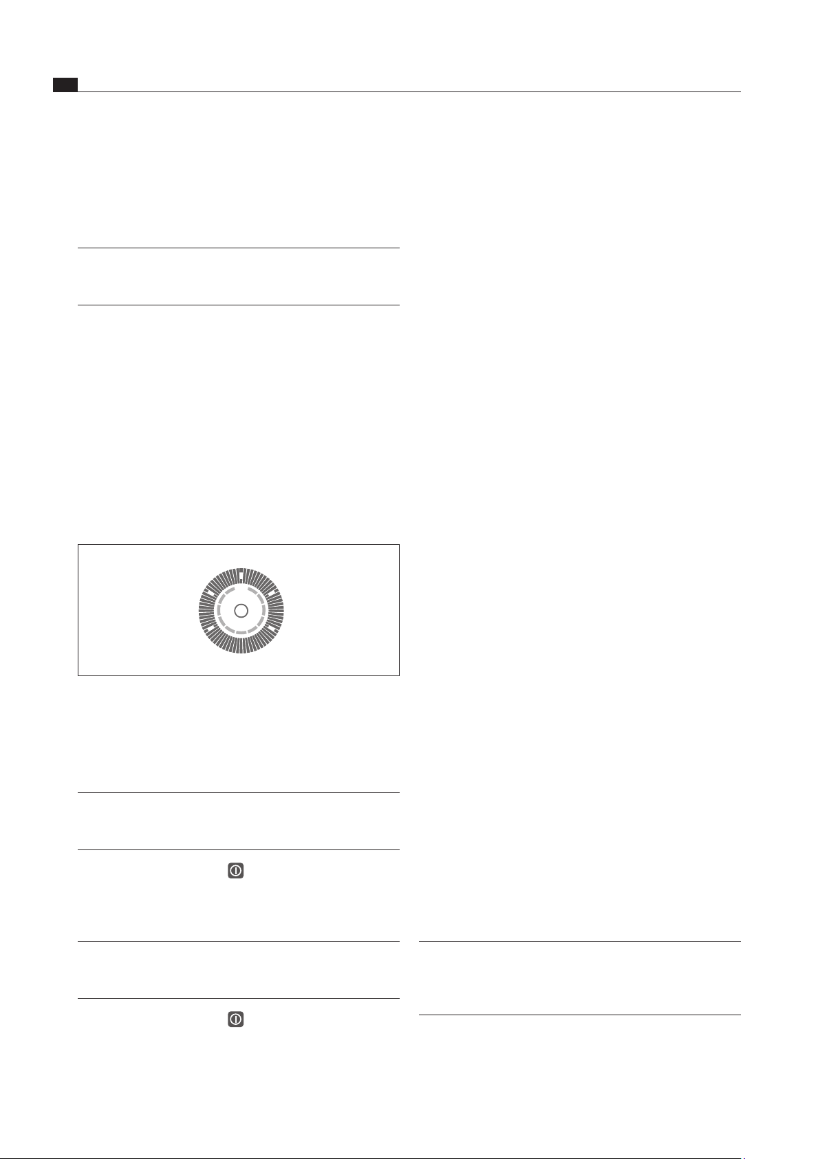
EN
32
Operation
www.bora.com
7 Operation
Observe all safety and warning information during
operation (see the Safety chapter).
INFO Only operate the cooktop if the stainless steel
grease filter and the air inlet nozzle have been
installed.
7.1 General operating instructions
The cooktop or cooktop extractor is operated using the
operating panel.
The selection of the cooking zone is performed by the
direct selection of the assigned sensor button on the
operating panel.
There are 9 power levels and one power setting available
for each cooking zone and the cooktop extractor.
The selection on the setting ring is performed by
direct selection or by uniformly swiping clockwise or
anti-clockwise.
0
3
1
6
9
P
Abb. 7.1 Setting ring with power level positions
7.2 Operating the cooktop
Switching on
INFO If the display shows
0
and no other input is
made, the device will switch off automatically
after 20 seconds.
Press the on/off switch to switch on the device.
The power level
0
is shown on the display.
Switching off
INFO Use the operating panel to switch off the
cooking zone after use. Do not rely on the pan
size recognition.
Press the on/off switch to switch off the device.
Pay attention to the residual heat display
(see the Device Description chapter).
7.2.1 Select cooking zone
Press the cooking zone button for the desired cooking
zone.
The
0
in the cooking zone indicator lights up more
brightly.
7.2.2 Adjusting the power level
Press the desired power level or
Press and uniformly swipe round the setting ring until
the desired power level is reached.
7.2.3 Changing the power level
Press the cooking zone button for the desired cooking
zone.
The cooking zone indicator lights up more brightly.
Select the desired power level.
7.2.4 Selecting the power setting
Press the cooking zone button for the desired cooking
zone.
The cooking zone indicator lights up more brightly.
Select power setting
P
.
The power setting
P
is displayed in the cooking zone
indicator.
7.2.5 Switching the power setting off early
Press the cooking zone button for the desired cooking
zone.
The cooking zone indicator lights up more brightly.
Select another power level.
The current power level is displayed in the cooking
zone indicator and the power setting is deselected.
7.2.6 Switching off the cooking zone
Press the cooking zone button for the desired cooking
zone.
The cooking zone indicator lights up more brightly.
Press the power level position
0
.
0
will appear on the display for a few seconds, then the
display will turn off.
7.2.7 Pay attention to the residual heat
display
After switching it off, the cooking zone remains hot.
H
is
displayed in the cooking zone indicator (residual heat
display). The cooking zone indicator will go out after
sufficient cooling time (temperature < 60°C).
Info While
H
is displayed in the cooking zone
indicator (residual heat display), do not touch
the cooking zone or place any heat-sensitive
objects on top of it. Risk of burns and fire!
Pay attention to the residual heat display.
Be careful not to touch or place objects on hot hobs.
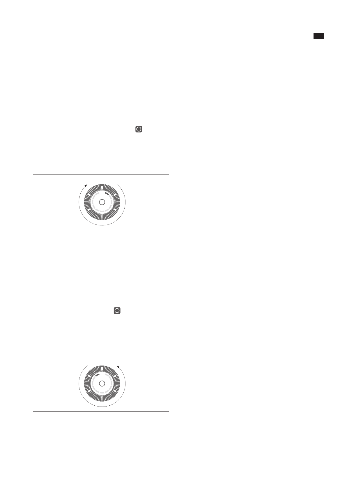
EN
33
Operation
www.bora.com
7.2.9 Bridging function
If the bridging function is active, two cooking zones will
operate at the same time on the same cooking level.
The front cooking zone will also control the rear, bridged
cooking zone.
7.2.10 Switching on the bridging function
Prerequisite
The cooktop is switched on.
All cooking zones are switched off.
Select the front cooking zones and hold down the
cooking zone selection button.
After 2 seconds, the rear cooking zone indicator will
show
%
and there will be a beep.
Press the cooking zone selection button for the rear
cooking zone to activate the bridging function.
Set a power level on the front cooking zone within
3 seconds.
The bridging function is activated and the rear cooking
zone indicator shows
%
.
If there is no input within 3 seconds, the bridging
function will end.
7.2.11 Switching off the bridging function
Switch the power level of the front cooking zone to
0
.
After 3 seconds, the bridging function is deactivated.
7.2.12 Automatic heat up function
Switching on the automatic heat up function
Prerequisite
The cooktop is switched on.
A cooking zone is switched on.
The automatic heat up function is activated if you
press and hold the desired continuous cooking level
(1 to 8) for 2 seconds.
The cooking zone indicator will display the symbol
A
to show that the automatic heat up function is
activated, as well as the continuous cooking level set,
for example
5
.
Changing the automatic heat up function
The power level of the continuous cooking level can be
changed within 15 seconds of activation.
Select the cooking zone.
Select the desired power level.
The selected continuous cooking level, e.g.
7
,
appears in the cooking zone indicator.
After the end of the automatic heat up function
(see the Device Description chapter), the cooking
session will continue with the desired continuous
cooking level, e.g.
7
.
7.2.8 Pause function
Switching on the pause function
Prerequisite
At least one cooking zone is in use.
INFO The pause function switches off automatically
after 10 minutes.
Press and hold the multi-function button for approx.
2-3 seconds.
If there is no input, the display will turn off after
5 seconds.
Swipe the setting ring in a circular, clockwise motion
to move from 1 to P.
0
1
P
Abb. 7.2 Switching on the pause function
The segments are displayed on the circular display in
accordance with the position.
I I
appears in all the cooking zone indicators and two
short successive beeps confirm activation.
The pause function is activated.
The cooktop extractor remains in operation at a lower
power level.
Switching off the pause function
Press the multi-function button .
If there is no input for 10 seconds, the pause function
will continue.
The setting ring will show the last segment.
Swipe the setting ring in a circular, anticlockwise
motion to move from P to 1.
0
1
P
Abb. 7.3 Switching o the pause function
The segments are displayed on the circular display in
accordance with the position.
All displays will show the power level that was
originally set.
The pause function is deactivated.
EN
34
Operation
www.bora.com
If there is no input, the timer display will turn off after
10 seconds.
Press the timer button multiple times to increase
the duration by +10 minutes each time.
Change the minutes in the timer display by making a
selection on the setting ring.
Once the desired time has been selected, the timer
starts automatically.
7.2.18 Switching off the short-time timer
(egg timer) early
You can switch off the short-time timer early by
changing the remaining timer setting to
00
.
7.2.19 Setting the automatic cut-off
You can set an automatic cut-off for every cooking zone.
INFO If several cooking zones are activated with an
automatic cut-off, the lowest timer value will
be shown and the timer control light for the
cooking zone in question will light up more
brightly.
Prerequisite
A cooking zone has been selected.
A power level was set.
Select the desired cooking zone.
Press the timer button within 3 seconds.
00 will appear in the timer display for a few seconds
and the dot next to the display will flash.
Press the timer button multiple times to increase
the duration by 10 minutes each time.
Change the minutes in the timer display by making a
selection on the setting ring.
Once the desired time has been selected, the timer
starts automatically.
After the last input, the set time will be displayed in the
timer display for a few seconds.
7.2.20 Switching off the automatic cut-off
early
The activated automatic cut-off function will end early if you
change the remaining timer setting to
00
;
switch off the cooktop using the on/off switch .
Change the power level to 0.
7.2.21 Changing the timer settings
Press the cooking zone button for the cooking zone for
which you wish to change the automatic cut-off.
Press the timer button multiple times to increase
the duration by 10 minutes each time.
Change the minutes in the timer display by uniformly
swiping the setting ring.
7.2.13 Switching off the automatic heat up
function
The activated automatic heat up function will end
prematurely if you
change the power level;
activate the power setting P;
activate the heat retention level
v
;
switch off the cooktop using the on/off switch .
7.2.14 Heat retention level
The cooktop is switched on.
Select a cooking zone.
Press the multi-function button several times to
increase the heat retention level.
The cooking zone indicator will display the relevant
heat retention level, e.g.
:
.
Press the multi-function button again.
The heat retention level is deactivated.
The cooking zone will automatically switch off after
8 seconds.
7.2.15 Using the timer function
Info The relevant timer control light shows whether
the timer is activated. The timer control
light lights up until the cooking zone has
automatically switched off after the pre-set
time has passed.
Prerequisite
The cooktop is switched on.
You can use 2 timer functions:
Short-time timer (egg timer – cooking zone does not
switch off automatically).
Automatic cut-off (for automatically switching off a
cooking zone).
You can set a time range of between 1 and 99 minutes for
both timer functions.
INFO After the end of the time set, 00 will appear in
the time display for a few seconds and the dot
in the display or the relevant timer control light
will flash. A signal tone will sound for a few
seconds.
The signal tone and the flashing are automatically
deactivated after 2 minutes.
7.2.16 Switching the signal beep off early
Press any sensor button on the operating panel to end
the signal tone prematurely.
7.2.17 Setting the short-time timer
(egg timer)
Press the timer button
00 will appear in the timer display for a few seconds
and the dot below the display will flash.
EN
35
Operation
www.bora.com
7.3 Operating the cooktop extractor
Prerequisite:
The cooktop with integrated cooktop extractor is
switched on.
Recommendations for efficient vapour extraction:
Always use a lid on pots that are particularly high.
This ensures effective vapour extraction. It also
reduces power consumption.
Only operate the cooktop extractor at the minimum
power level required for an effective vapour extraction.
This enables you to can improve the performance of
the odour filters in recirculation mode.
Only operate the hob at the minimum power level
required for cooking. This reduces the cooking vapours
and the power consumption.
Avoid strong drafts.
7.3.1 Selecting a cooktop extractor
Press the selection button for the cooktop extractor.
The
0
in the cooking zone indicator lights up more
brightly.
7.3.2 Adjusting the power level
Press the desired position on the setting ring to set the
power level or
Press and uniformly swipe round the setting ring until
the desired power level is reached.
7.3.3 Changing the power level
Press the selection button for the cooktop extractor.
The fan display lights up more brightly.
Select the desired power level.
The set power level is displayed in the fan display.
7.3.4 Selecting the power setting
Press the selection button for the cooktop extractor.
The fan display lights up more brightly.
Select power setting
P
.
The power setting
P
is displayed in the cooking zone
indicator.
The power setting
P
automatically switches to power
level
9
after 10 minutes.
7.3.5 Automatic cooktop extractor function
INFO If the automatic cooktop extractor function is
activated, the power level can be changed. The
automatic cooktop extractor function will be
reactivated after 10 minutes.
Press the selection button for the cooktop extractor.
Press the multi-function button .
The fan display lights up more brightly.
The automatic cooktop extractor function is activated.
A appears on the display.
7.2.22 Switching the childproofing feature
on/off
INFO If a cooking zone indicator alternates between
displaying
L
and
H
, the cooking zone is still hot.
Switching on the childproofing feature
Prerequisites:
The cooktop is switched on.
All cooking zones are switched off.
Press and hold the multi-function button for approx.
2-3 seconds.
If there is no input, the display will turn off after
5 seconds.
Swipe the setting ring in a circular, clockwise motion
to move from 1 to P.
0
1
P
Abb. 7.4 Switching on the childproong feature
The segments are displayed on the circular display in
accordance with the position.
L
is displayed in all cooking zone indicators.
The childproofing feature is activated.
Switching off the childproofing feature
The cooktop is switched on.
Press and hold the multi-function button for
approx. 2-3 seconds.
The setting ring will show the last segment.
Swipe the setting ring in a circular, anticlockwise
motion to move from P to 1.
0
1
P
Abb. 7.5 Switching o the childproong feature
The segments are displayed on the circular display in
accordance with the position.
All cooking zone indicators display
0
.
The childproofing feature is deactivated.
The power level you require can now be set for each
cooking zone.

EN
36
Operation
www.bora.com
Resetting the filter service display
If the activated charcoal filter has been replaced (with
recirculation only) and the stainless steel grease filter
has been cleaned, it will be necessary to reset the filter
service display.
Switch on the cooktop with integrated cooktop
extractor.
The fan display will show a flashing
F
.
Press the selection button on the cooktop extractor for
at least 4 seconds until a flashing
0
appears.
After a few seconds, a solid
0
will be displayed.
The filter service display has been reset.
7.5 Saving energy
Follow all of the energy-saving tips to use the cooktop
with integrated cooktop extractor in an energy-efficient
manner.
When purchasing cookware, pay attention to the
diameter of the base as the upper diameter of the pot
is usually specified. The diameter of the base is often
smaller.
Use pressure cookers. Due to the closed cooking
chamber and the overpressure, these save a great deal
of time and energy. The short cooking time also helps
preserve vitamins.
Make sure there is sufficient liquid in the pressure
cooker. An empty pot which is still being heated can
lead to overheating. This can damage both the cooking
zone and the pot.
If possible, always seal cookware using a suitable lid.
Choose a suitable size of cookware for the amount
of food you are cooking. A big pot that is barely filled
requires a lot of energy.
7.3.6 Switching off the automatic cooktop
extractor function
Press the selection button for the cooktop extractor.
Press the multi-function button .
The automatic cooktop extractor function is deactivated.
7.3.7 Automatic after-run
Press the selection button for the cooktop extractor.
The fan display lights up more brightly.
Select power level
0
The power level
n
is shown on the display.
The cooktop extractor switches off automatically after
20 minutes.
7.3.8 Switching off the automatic after-run
early
Press the selection button on the cooktop extractor
while the automatic after-run is active.
The automatic after-run is switched off.
7.3.9 Switching off the cooktop extractor
Press the selection button for the cooktop extractor.
The fan display lights up more brightly.
Select power level
0
.
The power level
0
is shown on the display.
Press the selection button for the cooktop extractor
again.
The device switches off.
or
Press the on/off switch to switch off the device.
7.4 Pay attention to the filter service
display
If
F
appears on the fan display, this means the service life of
the activated charcoal filter has expired (with recirculation
only) and the stainless steel grease filter needs to be
thoroughly cleaned:
Press the selection button for the cooktop extractor.
Press any button.
0
is shown in the fan display.
The filter service display is shown every time the cooktop
extractor is switched on and remains active until the filter
has been changed and the filter service display is reset.
The cooktop extractor can still be operated without
limitations.
Changing the filter
Switch off the cooktop with integrated cooktop
extractor.
Observe all warnings that are described in the Cleaning
chapter.
Replace the activated charcoal filter.
Clean the stainless steel grease filter, the air inlet nozzle,
the air guiding housing and the housing base.
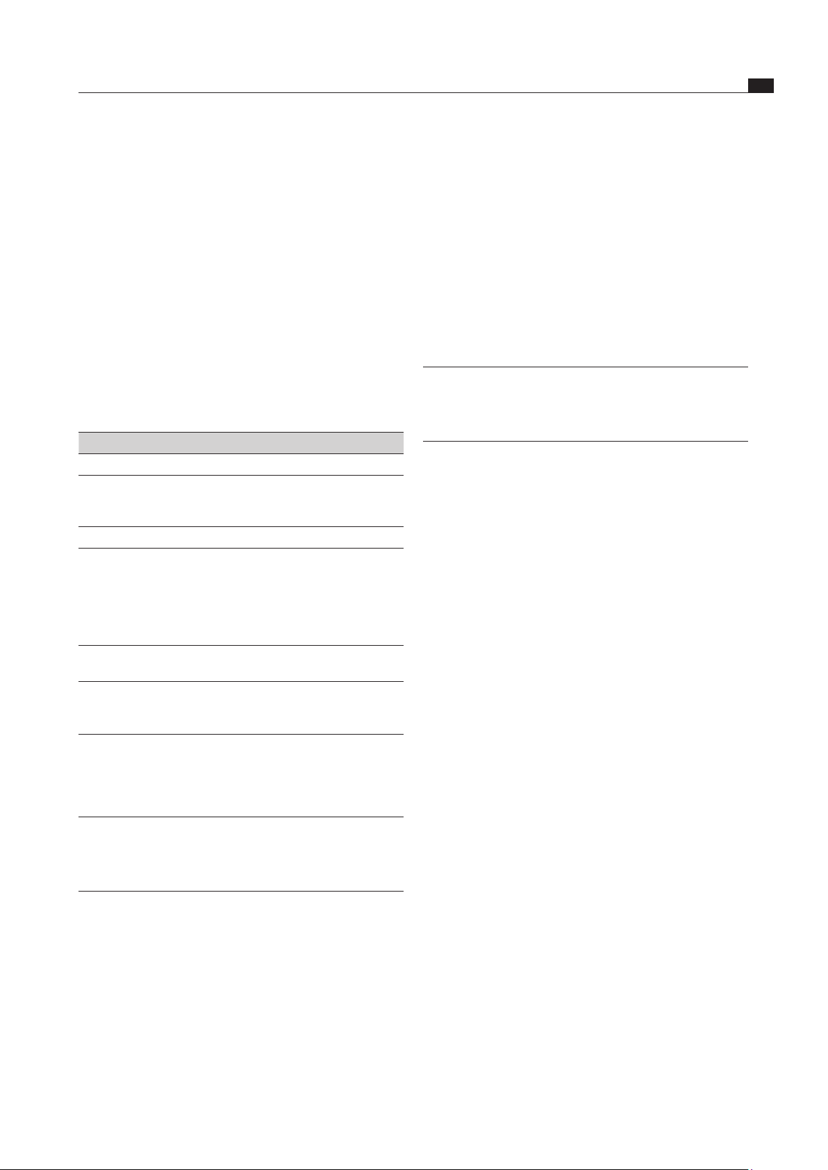
EN
37
Cleaning and maintenance
www.bora.com
8 Cleaning and
maintenance
Observe all safety and warning information
(see Safety chapter).
Follow the enclosed manufacturer’s information.
Make sure that the cooktop and cooktop extractor
have been switched off completely and have cooled
down prior to the planned cleaning and maintenance
work to prevent injury (see the Operation chapter).
Regular cleaning ensures the longevity of the product
and optimal functioning.
Adhere to the following cleaning and maintenance
cycles:
Component Cleaning cycle
Operating panel Immediately after every soiling
Cooktop Immediately after every soiling every week
thoroughly with standard commercially
available glass ceramic cleaners
Cooktop extractor Weekly
Air inlet nozzle and
stainless steel grease
filter
After every time you prepare very greasy
foods; at least weekly, when the fan
level indicator =
F
by hand or in the
dishwashing machine (at a max. 65 °C);
Only clean the stainless steel surfaces in
the polishing direction!
Air guiding housing Clean every 6 months or when replacing
the activated charcoal filter
Activated charcoal
filter (only for
recirculated air)
Replace after the build-up of odour, when
the extraction power has diminished or
the fan level indicator shows
F
Tab. 8.1 Cleaning cycles
8.1 Cleaning agents
INFO Due to the use of aggressive cleaning agents
and abrasion caused by the pot bases the
surface will become damaged and dark stains
will occur.
You need a special glass ceramic panel scraper and
suitable cleaning agents to clean the cooktop.
Never use steam cleaners, abrasive sponges, scouring
pads, or chemically aggressive cleaning agents (e.g.
baking oven spray).
Make sure that the cleaning agent does not contain
any sand, soda, acids or chloride.
For air inlet nozzle and grease filter
Do not use any aggressive, acidic or alkaline cleaning
agents.
8.2 Maintaining the cooktop
Do not use the cooktop as a worktop or shelf.
Do not push or pull cookware across the cooktop.
Always lift pots and pans.
Keep the cooktop clean.
Remove any kind of soiling immediately.
Only use cookware which is suitable for glass ceramic
panels (see the Device description chapter)
8.3 Cleaning the cooktop
INFO When the cooktop extractor is switched on,
the air inlet nozzle is installed to ensure that no
small and light objects, such as cleaning wipes
made of fabrics or paper are sucked in.
Make sure that the cooktop is switched off (see
Operating chapter).
Wait until all cooking zones are cold.
Remove all coarse soiling and food residues from the
cooktop with a glass ceramic scraper.
Apply the cleaning agent onto the cold cooktop.
Rub the cleaning agent with a paper towel or a clean cloth.
Wipe off the cooktop while wet.
Rub the cooktop dry with a clean cloth.
When the cooktop is hot:
Immediately remove molten residues of plastic,
aluminium film, sugar or foods containing sugar with
a glass ceramic scraper from the hot cooking zone to
prevent burning them in.
Special soiling
Heavy soiling and stains (limescale stains, pearly
shimmering stains) are best to be removed if the
cooktop is still warm.
Soften dried dirt residues using a damp cloth.
Remove dirt residues with the glass ceramic scraper.
Always remove grains, crumbs or the like which fall
onto the cooktop during general cooking work right
away to prevent the surface from being scratched.
Coloured changes and shiny surfaces are not cooktop
damage. They do not impact on the function of the
cooktop and the stability of the glass ceramic.
Discolourations to the cooktop arise from residues which
are not removed and have been burnt in.
Glossy spots are caused by the abrasion of the pot base,
especially when using cooking utensils with aluminium
bases, or by unsuitable cleaning agents. They are very
hard to remove.
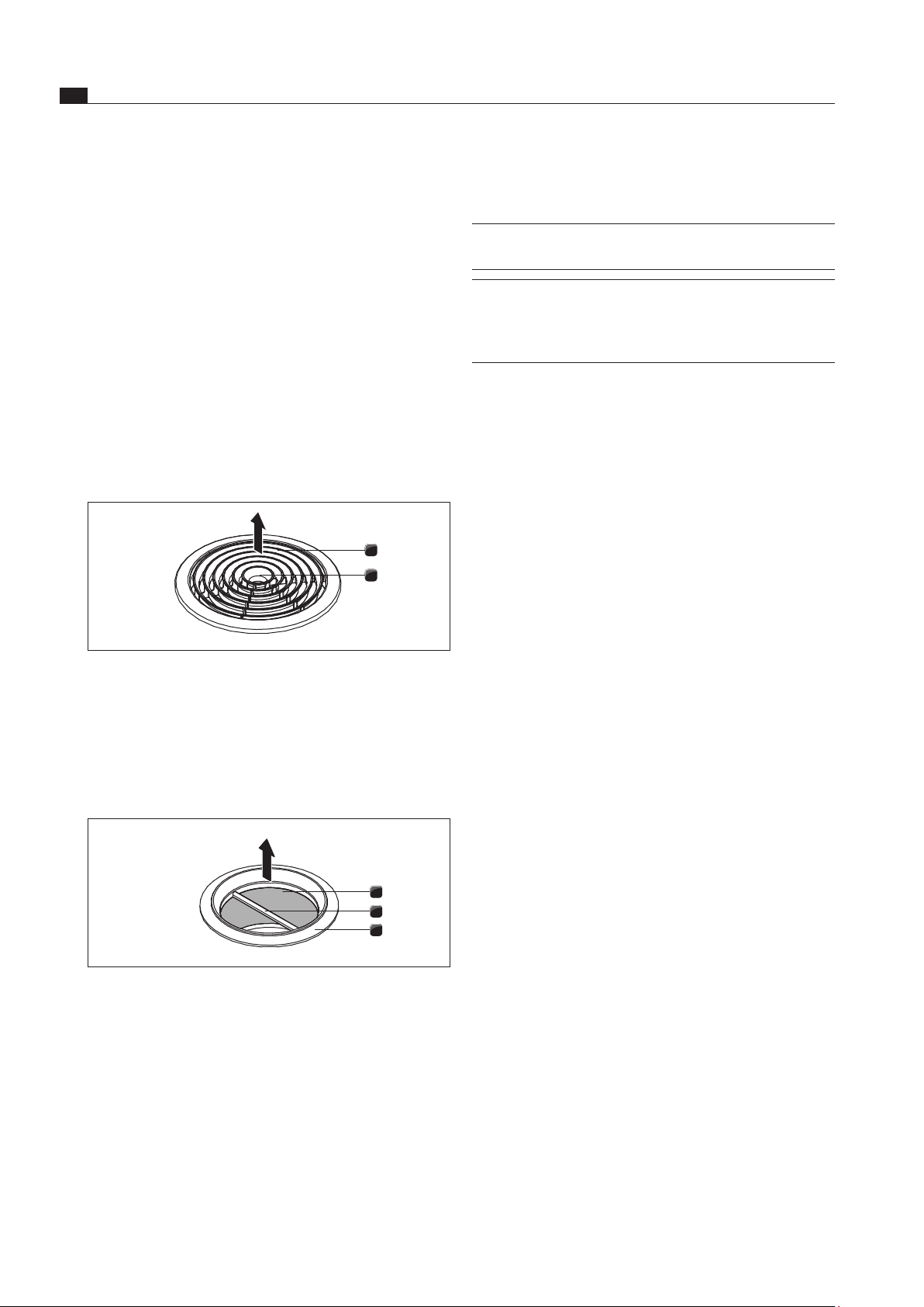
EN
38
Cleaning and maintenance
www.bora.com
8.4.2 Cleaning the air inlet nozzle and
stainless steel grease filter
INFO Clean the stainless steel surfaces in the
polishing direction only.
INFO If the stainless steel grease filter can no
longer be cleaned completely, this means the
stainless steel grease filter will need to be
replaced.
Manual cleaning
Use a degreasing cleaning agent.
Rinse the inlet nozzle and stainless steel grease filter
with hot water.
Use a soft brush to clean the inlet nozzle and stainless
steel grease filter.
After cleaning, rinse the inlet nozzle and stainless steel
grease filter well.
Cleaning in the dishwasher
Rinse the air inlet nozzle and the stainless steel grease
filter with a rinsing program at a maximum of 55 °C.
8.4.3 Installing stainless steel grease filter
and air inlet nozzle
Grab the stainless steel grease filter using the handle [2]
(Fig. 7.2)
Insert the stainless steel grease filter [1] into the
suction opening.
Make sure that the stainless steel grease filter rests
against the bottom housing base. A lock is not needed
and is not provided.
Reach into the access opening [2] of the inlet nozzle
with your hand (Fig. 7.1).
Insert the air inlet nozzle (Fig. 7.1; [1]) centrally into
the suction opening.
Press the air inlet nozzle upwards until it engages.
8.5 Cleaning the air guiding housing
Greasy deposits and limescale residues from the cooking
vapour can accumulate on the surface of the air guiding
housing. Regular, thorough cleaning (see Table 7.1) is
thus necessary.
The air guiding housing is on the underside of the cooktop
in the floor unit.
8.5.1 Opening the air guiding housing
Make sure that the cooktop and cooktop extractor are
switched off (see Operating chapter).
Wait until the fan display is
0
.
8.4 Cleaning the cooktop extractor
The air inlet nozzle and the stainless steel grease filter
absorb the greasy components of the kitchen vapour.
Make sure that the cooktop and cooktop extractor are
switched off (see Operating chapter).
Wait until the fan display is 0.
Clean the cooktop extractor in accordance with the
cleaning cycles (see Tab. 7.1).
Clean the surfaces of the exhaust air system using a
soft damp cloth, detergent or a mild window cleaning
agent.
Soften dried-on dirt residues using a damp cloth
(do not scratch!).
8.4.1 Removing the air inlet nozzle and
stainless steel grease filter
2
1
Abb. 8.1 Removing the air inlet nozzle
[1] Air inlet nozzle
[2] Access opening
Prerequisite: The fan level indicator indicates
0
.
Reach into the access opening [2] with your hand.
Remove the air inlet nozzle [1] out upwards.
3
2
1
Abb. 8.2 Removing the stainless steel grease lter
[1] Stainless steel grease filter
[2] Handle
[3] Suction opening
Grab the stainless steel grease filter using the
handle [2].
Pull the stainless steel grease filter [1] out of the
suction opening [3] upwards.
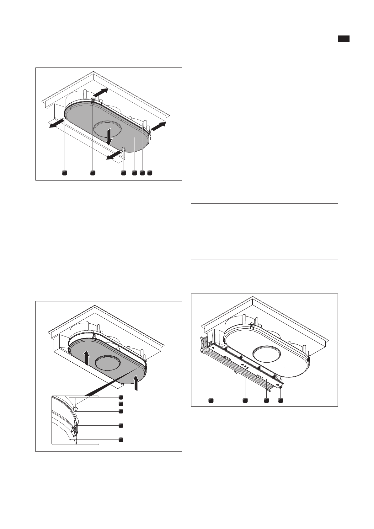
EN
39
Cleaning and maintenance
www.bora.com
Using both hands, position the housing base [5] so that
the position of the locking straps [4] on the housing base
match the position of the hooks [3] on the housing.
Insert the housing base at the sealing groove [2] of the
air guiding housing [1].
Press the housing base [5] upwards until the 4 locks
(2 front, 2 rear) engage into the hooks [3].
Check that all 4 locking straps [4] have correctly engaged.
8.6 Replacing the activated charcoal
filter
Two activated charcoal filters are used only when the
cooktop extractor is being operated in recirculated
air mode. The activated charcoal filter binds odorous
materials which arise during cooking.
INFO The activated charcoal filters must be replaced
when the fan level indicator indicates
F
(filter
service display).
BAKF activated charcoal filters can be
pur chased from your specialist.
You can also contact BORA on its homepage
http://www.bora.com.
Make sure that the cooktop and cooktop extractor are
switched off (see Chapter 6.1).
Wait until the fan display is
0
.
1
3 12
Abb. 8.5 Releasing the activated carbon lter housing lid
[1] Outer locks
[2] Activated carbon filter housing cover
[3] Middle lock
4 41 13 2
Abb. 8.3 Opening the air guiding housing
[1] Front locks
[2] Air guiding housing
[3] Housing base
[4] Rear locks
Hold the housing base with one hand [3].
Open both locks on the rear [4].
Open both front locks [1].
Remove the housing base [3].
Clean the air guiding housing [2] and the housing base
[3] with a mild cleaning agent.
8.5.2 Closing the air guiding housing
1
2
3
4
5
Abb. 8.4 Closing the air guiding housing
[1] Air guiding housing
[2] Sealing groove
[3] Hooks
[4] Locking strop
[5] Housing base
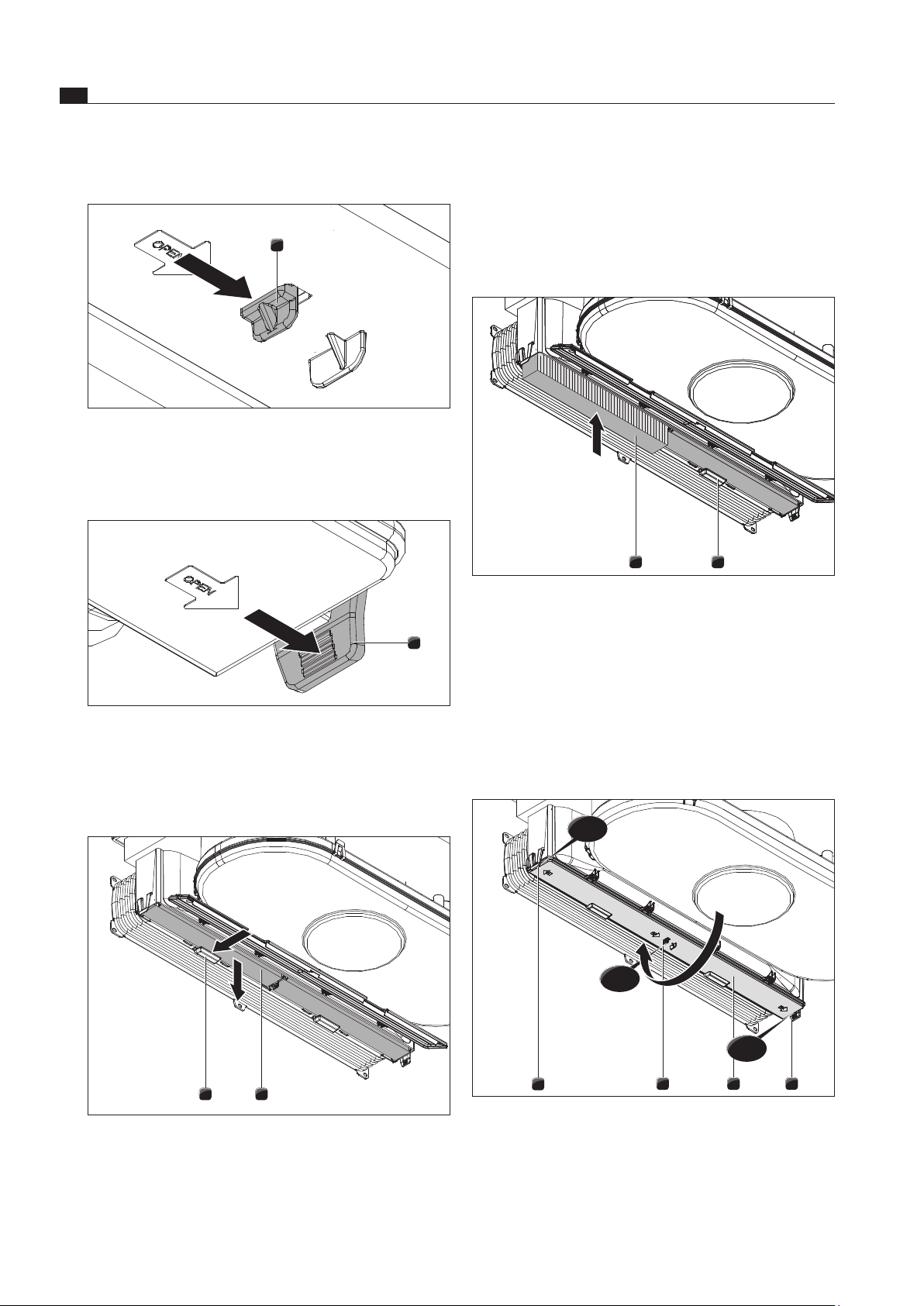
EN
40
Cleaning and maintenance
www.bora.com
Remove the activated charcoal filter by moving it
downwards.
Dispose of used activated charcoal filters with
household waste.
Inserting the activated charcoal filter
2 1
Abb. 8.9 Inserting the activated charcoal lter
[1] Filter bracket
[2] Activated charcoal filter
Position the new activated charcoal filter [2] in such a
way that the directional arrow is pointing to the rear
and is visible from below.
Move the activated charcoal filter into the housing.
Press the activated charcoal filter upwards until the
filter retainer [1] engages.
1
1 12
click
click
click
Abb. 8.10 Closing the activated charcoal lter housing lid
[1] Locks
[2] Activated carbon filter housing cover
Fold the activated charcoal filter housing lid [2] by
moving up upwards.
Press on the activated charcoal filter housing lid until
the locks [1] engage.
Removing the activated carbon filter
1
Abb. 8.6 Opening middle lock
[1] Lock, middle
Open the lock [1] in the middle.
1
Abb. 8.7 Opening outer locks
[1] Outer lock
Open both outer locks [1].
Fold the lid (Fig. 7.5; [2]) down until it engages.
2 1
Abb. 8.8 Removing the activated carbon lter
[1] Activated charcoal filter
[2] Filter bracket
Hold the activated charcoal filter with one hand [1].
Push the filter retainer [2] to the back.
EN
41
Troubleshooting
www.bora.com
9 Troubleshooting
Operating situation Cause Remedy
The cooktop or the fan
cannot be switched on.
The fuse or the automatic
circuit breaker of the electrical
installation of the apartment
and/or house is defective.
Replace the fuse. Switch the automatic circuit breaker
back on.
The fuse or the automatic circuit
breaker trips several times.
Call the BORA Service Team.
The power supply is disconnected. Have a specialist electrician inspect the power supply.
Odours and vapours arise when the
new cooktop is put into operation.
This is normal on brand-new
appliances.
Wait a few operating hours.
Contact the Service Team if the odour persists.
v
is displayed in the cooking zone
indicator.
No or unsuitable cookware has been
placed on the cooking zone.
Only use suitable cookware. Select the cookware size
depending on the cooking zone
(see the Device Description chapter).
L
is displayed in the cooking zone
indicator.
The childproofing feature is
activated.
Switch off the childproofing feature
(see the Operation chapter).
A cooking zone or the entire cooktop
switches off automatically.
The operating time of a cooking zone
has been exceeded.
Put the cooking zone back into operation
(see the Operation chapter).
The overheating protection has tripped. (see the Device Description chapter)
The power setting is automatically
shut off prematurely.
The overheating protection has tripped. (see the Device Description chapter)
ER03
is shown across all 4 cooking
zone indicators and the cooktop swit-
ches off during operation.
One or more sensor buttons are
covered, e.g. due to finger contact or
by objects placed on them.
Clean the operating panel or remove objects
(see the Device description chapter).
The cooling fan continues
running after the cooktop has been
switched off.
The cooling fan will continue to run until
the cooktop has cooled down and will
then switch off automatically.
Wait until the cooling fan switches off
automatically.
E
is displayed in the cooking zone
indicator.
An error has occurred in the electronic
system.
Interrupt the cooktop power supply for approx.
1 minute. If th
e problem continues to persist after the
power supply has been restored, write down the error
number and contact the BORA Service Team.
F
is displayed in the fan level
indicator.
The period of use of the filters has been
exceeded.
Replace the activated charcoal filter (with recirculation
only) and thoroughly clean the stainless steel grease
filter. In case of heavy soiling, replacing the stainless
steel grease filter is also recommended (see Cleaning
and maintenance chapter).
The extraction performance of the
cooktop extractor has decreased.
The stainless steel grease filter is
heavily soiled.
Clean or replace the stainless steel grease filter.
The activated charcoal filter is heavily
soiled (BFIU only).
Replace the activated charcoal filter.
There is an object in the air guiding
housing (e.g. cleaning cloth).
Remove the trapped object.
Er8 1
or
Er82
is shown in the fan
level indicator.
The fan is defective or a duct
connection has become loose.
Call the BORA Service Team.
E
is displayed in the fan level
indicator. The fan cannot be
switched on.
The Home-In contact is broken. When using a window contact switch (safety device),
the window must be open when the fan is operating.
The safety device is defective. Call the BORA Service Team.
Tab. 9.1 Resolving a fault
In all other instances, call the BORA Service Team (see the Warranty, service and spare parts chapter).
EN
42
Decommissioning, disassembly and disposal
www.bora.com
10 Decommissioning,
disassembly and
disposal
Observe all safety and warning information
(see Safety chapter).
Follow the enclosed manufacturer’s information.
10.1 Decommissioning
Decommissioning is considered the final decommissioning
and disassembly. After decommissioning, the device can
either be built into another piece of furniture, sold on
privately, or disposed of.
INFO Disconnecting and connecting the electricity
and gas connection may only be carried out by
certified experts.
Switch off the device before decommissioning
(see Operating chapter)
Disconnect the device from the voltage supply.
10.2 Disassembly
The removal requires that the device is accessible
for disassembly and was separated from the voltage
supply. On gas-powered devices, make sure that the gas
connection is complete.
Undo the mounting brackets.
Remove the silicone joints.
Disconnect the duct from the cooktop extractor.
Remove the device from the worktop upwards.
Remove further accessory parts.
Remove the old appliance and dirty accessory as
described under “Disposing of the product in an
environmentally friendly way”.
10.3 Disposing of the product in an
environmentally friendly way
Disposal of transport packaging
INFO The packaging protects the device against
transport damages. The packaging is made of
materials that are environmentally friendly and
easy to dispose of and can therefore be recycled.
Returning the packaging material into the material cycle
saves resources and reduces the waste production. Your
specialist supplier will take the packaging back.
Hand the packaging to your specialist supplier
or
Dispose of the packaging properly taking into account
the regional regulations.
Disposing of the old appliance
Electrical devices marked with this
symbol should not be disposed of as
household waste at the end of its life.
They must be taken to a collection
centre for recycling electrical or
electronic non-heating appliances.
For information, please contact your
city or local authorities.
Waste electric and electronic equipment often still
contains valuable materials. They do, however, also
contain harmful substances that were required for their
correct functioning and safety. When disposed of in the
residual waste or if not handled correctly, they may cause
harm to the health of people and the environment.
Therefore do not dispose of your old appliance as
household waste.
Take the old appliance to a regional collection centre
for return and recycling of electronic and electrical
parts and other materials.

EN
43
Warranty, service and spare parts
www.bora.com
11 Warranty, service and
spare parts
Observe all safety and warning information
(see Safety chapter).
11.1 Warranty
The warranty period shall be 2 years.
11.2 Service
BORA Service:
see reverse side of operating and assembly instructions
+800 7890 0987
In the case of faults you cannot fix yourself,
contact your BORA specialist supplier or the
BORA Service Team.
The After Sales Service will require the type designation
and the serial number of your device (FD number). This
information is provided on the nameplate or on the back
of the manual as well as on the device.
11.3 Spare parts
Only use original spare parts when making repairs.
INFO Spare parts can be obtained from your BORA
dealer, the BORA online service website at
www.bora.com/service or by calling the
service number provided.

Germany::
BORA Lüftungstechnik GmbH
Rosenheimer Str. 33
83064 Raubling
Germany
T +49 (0) 8035 / 907-240
F +49 (0) 8035 / 907-249
www.bora.com
Austria:
BORA Vertriebs GmbH & Co KG
Prof.-Dr.-Anton-Kathrein-Straße 3
6342 Niederndorf
Österreich
T +43 (0) 5373 / 62250-0
F +43 (0) 5373 / 62250-90
www.bora.com
Europe:
BORA Holding GmbH
Prof.-Dr.-Anton-Kathrein-Straße 3
6342 Niederndorf
Austria
T +43 (0) 5373 / 62250-0
F +43 (0) 5373 / 62250-90
www.bora.com
Australia – New Zealand:
BORA APAC Pty Ltd
A/ 91-95 Victoria Road
Drummoyne NSW 2047
Australia
T +61 2 7900 5580
F +61 2 8076 3514
www.boraapac.com.au
Nameplate:
+800 7890 0987

