Loading ...
Loading ...
Loading ...
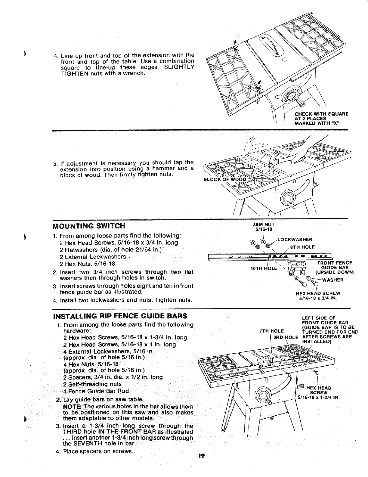
4. Lineup front andtopof theextensionwith the
front and top of the table. Usea combination
square to line-up these edges. SLIGHTLY
TIGHTENnutswitha wrench.
5. tf adjustment _s necessary you should tap the
extension into position using a hammer and a
block of wood. Then firmly tighten nuts.
BLOCK OF WOOD :
\
CHECK WITH SQUARE
AT 2 PLACES
MARKED WITH "X"
ii
\
MOUNTING SWITCH
1• From among loose parts find the following:
2 Hex Head Screws 5/16-18 x 3/4 in. long
2 Flatwashers (alia. of hole 21/64 in.)
2 External Lockwashers
2 Hex Nuts 5/!6-18
2. Insert two 3/4 inch screws through two flat
washers then through holes in switch.
3. Insert screws through holes eight and ten in front
fence guide bar as illustrated•
4. Install two Iockwashers and nuts. Tighten nuts.
w_
JAM NUT
5/t6-18
"_ 8 /LOCKWASHER
@-_ ,8TH HOLE
%'_-'-- WASH ER
t
HEX HEAD SCREW
5/16-18 x 3/4 IN.
INSTALLING RiP FENCE GUIDE BARS
1. From among the loose parts find the following
hardware:
2 Hex Plead Screws, 5/16-18 x 1-3/4 in. long
2 Hex Head Screws, 5/16-18 x 1 in. long
4 External Lockwashers, 5/16 in.
(approx. dia. of hole 5/16 in.)
4 Hex Nuts, 5/16-18
(approx. dia. of hole 5/16 in.)
2 SpaceFs, 3/4 in. dia. x !/2 in. long
2 Self-threading nuts
1 Fence Guide Bar Rod
2. Lay guide bars on saw table,
NOTE: The various holes in the bar allows them
to be positioned on this saw and also makes
them adaptable to other models.
3. Insert a 1-3/4 inch long screw through the
THIRD hole IN THE FRONT BAR as illustrated
•.. Insert another 1-3/4 inch long screwthrough
the SEVENTH hole in bar.
4. Place spacers on screws.
19
7TH HOLE
3RD HOLE
LEFT SiDE OF
FRONT GUIDE BAR
(GUIDE BAR IS TO BE
TURNED END FOR END
AFTER SCREWS ARE
INSTALLED)
SCREW
5/16-18 x 1-3./4 IN.
Loading ...
Loading ...
Loading ...