Loading ...
Loading ...
Loading ...
Part Number 550-142-300/0520
55
CGa Series 3 Gas-Fired Water Boiler — Boiler Manual
11b
Troubleshooting — spark-pilot boilers (continued)
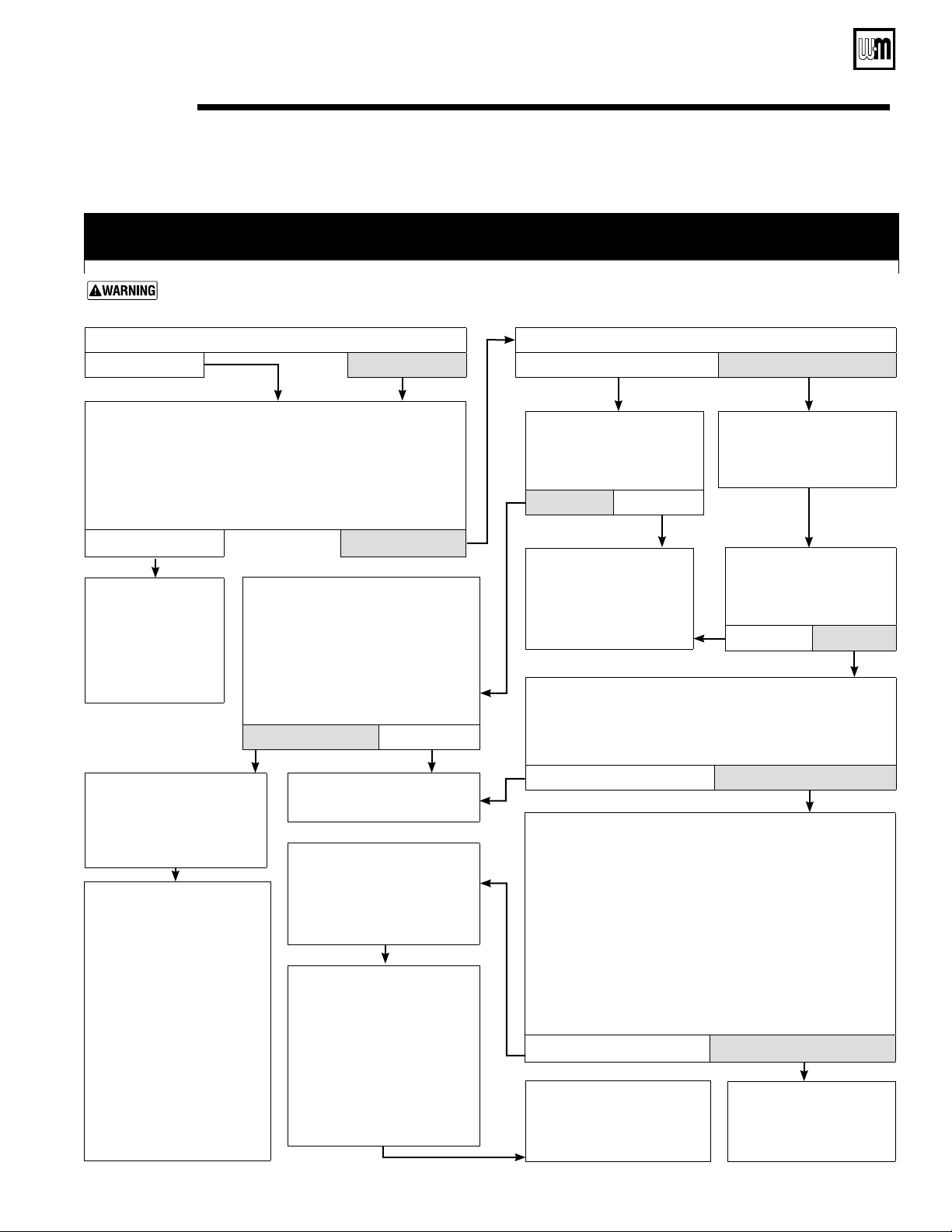
CHART 5 –– Spark-ignited pilot –– FLAME light flashing and POWER light on steady
ALSO –– Troubleshooting failure to establish main flame
Electrical shock hazard — Wherever you see
▲
TURN OFF POWER
▲
, follow the instructions. Failure to follow
instructions could result in severe personal injury, death or substantial property damage.
• Is pilot flame visible through inspection port ?
No Yes
Are main manual shutoff valve and gas valve open?
No Yes
• ▲ TURN OFF POWER ▲
to boiler at service switch or breaker.
• Open main manual shutoff valve and boiler gas valve (per
Operating instructions in this manual). Wait at least 45
seconds.
• Turn on power at service switch or breaker. Allow boiler to cycle.
Does FLAME light flash now?
No Yes
• ▲ TURN OFF POWER ▲
to boiler at service switch or
breaker.
• Remove base access panel
(see Figure 32, item 4,
page 60 for location.
• Contact gas supplier to correct
pressure or gas supply.
• Check the voltage across
main gas valve terminals
of the gas valve.
Is 24 VAC present there?
Yes No
• Make sure ground wire
terminal is securely fastened
to control module mounting
screw.
• Verify inlet gas pressure at gas valve:
Natural gas – 5.0” w.c. min/14.0” w.c. max
Propane – 11.0” w.c. min/14.0” w.c. max
Is gas present at gas valve inlet and within above range?
No Yes
• ▲ TURN OFF POWER ▲
to boiler at service switch or breaker.
• Check flame signal – Detach sense lead from ignition control
(Figure 30, Item 8, page 50)
.
• Connect negative lead of MICROAMMETER to control sense
terminal
(Figure 30, Item 8, page 50)
. Connect positive
lead of MICROAMMETER to sense wire.
• DISCONNECT red wire connected to main gas valve terminal
of the gas valve.
• Turn on power to boiler and allow to cycle. As soon as pilot
is burning, the MICROAMMETER should read at least 1.0
microamp.
Is flame signal at least 1.0 microamp ?
No Yes
• Check the voltage across
main gas valve terminals
of the gas valve.
Is 24 VAC present there?
No Yes
• If the wiring from the
control module to gas valve
is intact, replace the control
module.
• Retest.
• Verify inlet gas pressure at gas
valve:
Natural gas – 5.0” w.c. min/14.0”
w.c. max
Propane – 11.0” w.c. min/14.0”
w.c. max
Is gas present at gas valve inlet and
within above range?
Yes No
• Boiler should be in
normal operating
sequence.
• Observe operation
until thermostat is
satisfied and vent
damper has closed.
• Verify pilot gas line is not
kinked, obstructed or dam-
aged and is correctly attached
to pilot and gas valve.
• Verify pilot ignition electrode,
electrode ceramic and spark
lead wire from control are in
good condition. Spark gap
should be approximately 1/8”.
• Correct any above problems,
replacing pilot if burner or wir
-
ing is damaged.
• Reinstall base access panel to
operate boiler for retest after
any changes or corrections.
• If none of the above corrects
problems, then replace the
control module, reinstall base
access panel, and retest.
• ▲ TURN OFF POWER ▲
to boiler at service switch or
breaker.
• Remove base access panel
(see Figure 32, item 4,
page 60 for location.
• Verify pilot burner is securely at-
tached to pilot bracket, bracket
is securely attached to cross-tie,
and there is no corrosion on the
ground path for flame sense.
• Verify that pilot flame rod, flame
rod ceramic and lead wire from
control module to flame rod are
in good condition.
• Correct any above problems,
replacing pilot if burner or wir-
ing is damaged.
• If none of the previous steps
(including replacing pilot)
corrects problem, then replace
the control module, reinstall
base access panel and retest.
• If the wiring from the
control module to gas
valve is intact, replace the
control module and retest.
Loading ...
Loading ...
Loading ...