Loading ...
Loading ...
Loading ...
Part Number 550-142-300/0520
32
CGa Series 3 Gas-Fired Water Boiler — Boiler Manual
See Section 9 for operation and operating information.
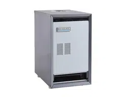
Figure 21 Typical pilot burner flame
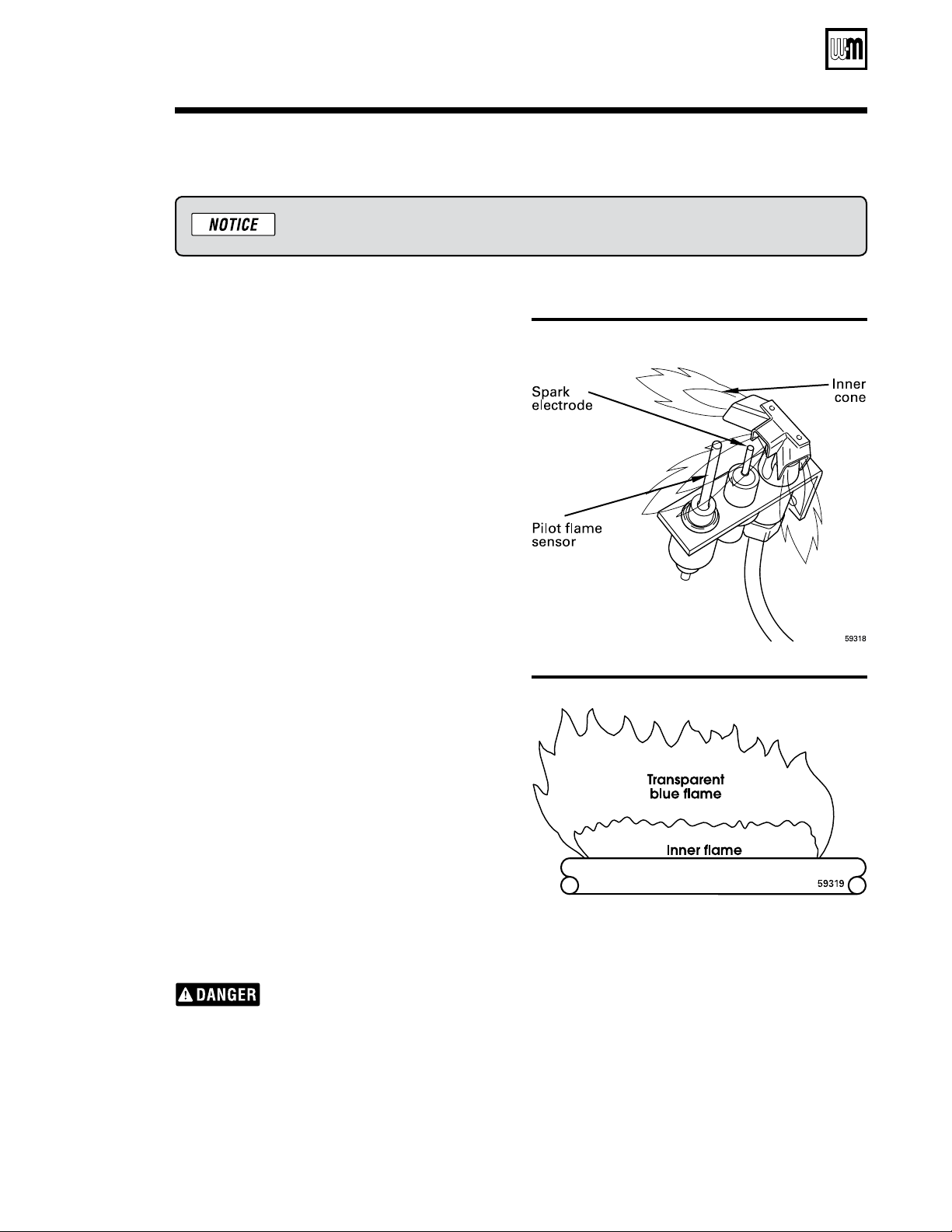
Figure 22 Typical main burner flame
Check vent system operation
1. Check vent system at least once a month during
heating season. With boiler firing, hold candle or
match below lower edge of draft hood “skirt”. If
flame does not blow out, but burns undisturbed,
vent system is functioning properly. If flame blows
out or flickers drastically, inspect vent system for
obstructions or other causes of improper venting
(such as exhaust fans in boiler room).
Check burner flames
Pilot burner flame (Figure 21)
PROPER pilot flame
1. Blue flame.
2. Inner cone engulfing pilot flame sensor (spark-
ignited pilot).
3. Pilot flame sensor glowing cherry red.
IMPROPER pilot flame
1. Overfired — Large flame lifting or blowing past pilot
flame sensor.
2. Underfired — Small flame. Inner cone not engulfing
pilot flame sensor.
3. Lack of primary air — Yellow flame tip.
Main burner flame (Figure 22)
PROPER main burner flame
1. Yellow-orange streaks may appear (caused by dust).
IMPROPER main burner flame:
1. Overfired — Large flames.
2. Underfired — Small flames.
3. Lack of primary air — Yellow tipping on flames
(sooting will occur).
Check vent damper operation
1. Raise room thermostat to call for heat — Vent
damper actuator will slowly open vent damper.
2. When vent damper is fully open — Pilot will light,
then allow main burners to ignite.
Vent damper must be fully open
before main burners light. If vent
damper does not fully open, flue
products such as carbon monoxide
will escape into house, causing se-
vere personal injury or death.
3. Lower thermostat setting — Main burner flames
will go out, then vent damper will close.
4. Repeat Steps 2 through 4 several times to verify
operation.
5. Return thermostat to normal setting.
6. Set thermostat heat anticipator setting indicated on
wiring diagram.
Start-up — verify operation
6d
Loading ...
Loading ...
Loading ...