Loading ...
Loading ...
Loading ...
Part Number 550-142-300/0520
49
CGa Series 3 Gas-Fired Water Boiler — Boiler Manual
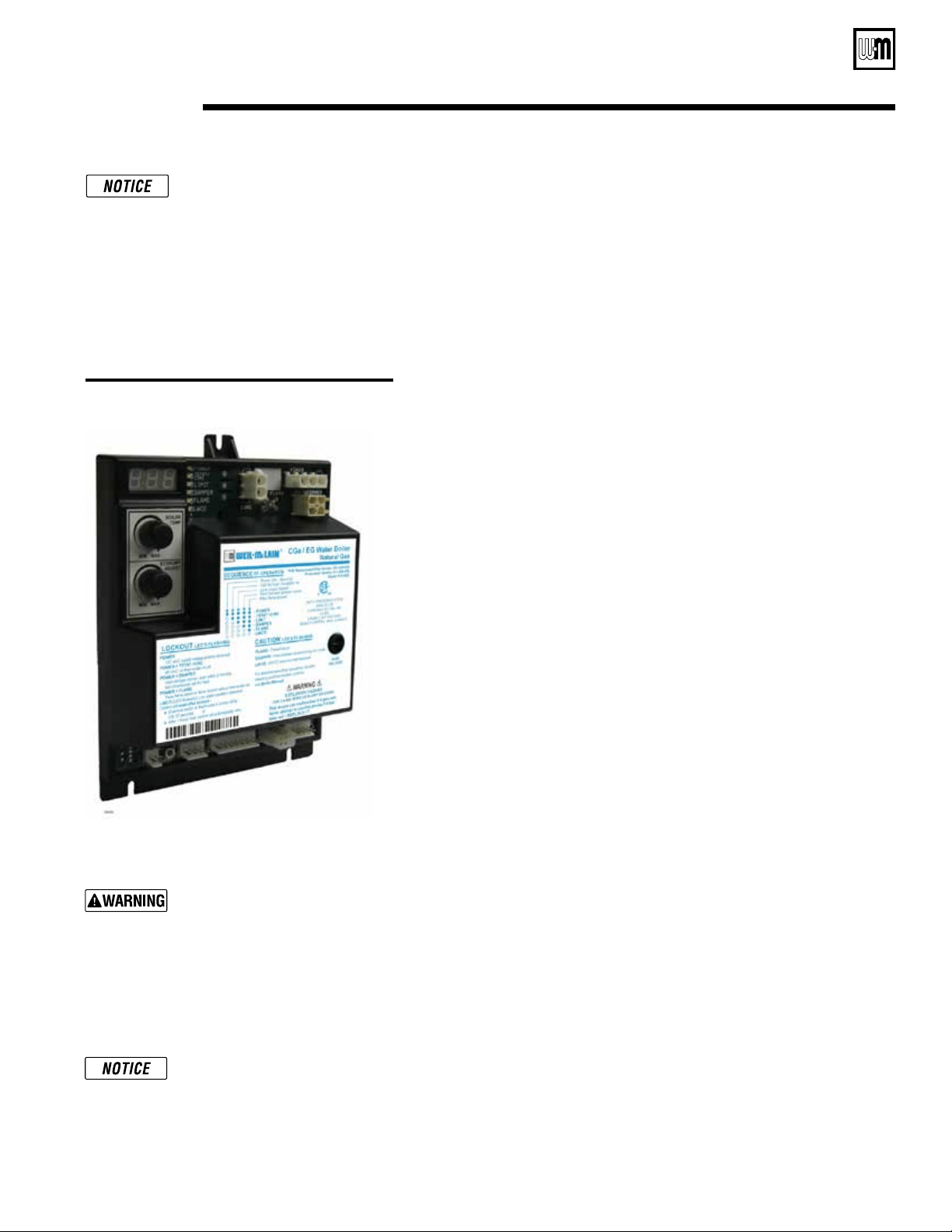
Figure 29 CGa/EG Ignition control module
The information on this page and
pages 50 through 57 apply only to
spark-ignited pilot CGa boilers.
These boilers are equipped with
an ignition control module that
has indicator lights to show control
status. Charts 1 through 7, pages
51- 57, help you identify problems
based on indicator light condi-
tions.
Troubleshooting — spark-pilot boilers
11b
Control module
Solder or water splatter be-
tween plugs and circuit board
can cause improper operation of
control module. Place a shield over
the boiler internal controls and
components during installation.
Failure to comply could result in
severe personal injury, death or
substantial property damage.
Make sure ground wiring is in-
stalled per wiring diagram. Good
grounding is extremely important
for proper operation.
Control indicator lights —
HARD LOCKOUT Summary (Flashing LED’s)
MAY remove 120 VAC power for more than 2 seconds to clear lockout OR
ignition control will automatically restart sequence of operation after 1 hour
waiting period after fault condition is cleared.
INDICATOR LIGHT
CONDITION
POWER
Flashes once per second
120 VAC connection to boiler
reversed or there is insufcient
earth ground.
Flash code 2* Internal fault, microprocessor or
memory.
Flash code 3* Internal fault, LWCO circuit.
Flash code 4* Unused.
Flash code 5* Internal fault, water thermistors
disagree.
Flash code 6*
Flashes once per second
Internal fault, gas valve circuit.
* Flash code pattern: POWER LED ashes 2, 3, etc. times
rapidly followed by 2 seconds off, then repeats.
ALL LED’S FLASHING Failure to establish pilot
ame after 4 attempts.
SOLID LWCO LED Low water condition occurred.
SOFT LOCKOUT Summary (Flashing LED’s)
MAY remove 120VAC power for more than 2 seconds, cycle thermostat for
between 2 and 20 seconds, OR ignition control will automatically restart
sequence of operation after 1 hour waiting period.
INDICATOR LIGHT CONDITION
POWER + TSTAT/CIRC High voltage detected on TSTAT circuit.
POWER + DAMPER Damper stuck closed or unable to close end
switch within 45 seconds from TSTAT call.
POWER + FLAME Flame sensed without call for heat or out
of sequence during ignition trial.
CAUTION Summary (Flashing LED’s)
INDICATOR LIGHT CONDITION
DAMPER Damper end switch opened after it had
been proven closed.
LIMIT Fault detected in temperature sensing
hardware.
FLAME Flame loss or ame not sensed during
trial for ignition.
LWCO LWCO circuit approaching lockout state.
Sensor requires maintenance. LWCO
LED will ash 3 times when maintenance
is required.
Troubleshooting the control module
See Figure 30, page 50, for location of harness plug receptacles and plugs on the
control module.
Loading ...
Loading ...
Loading ...