Loading ...
Loading ...
Loading ...
Part Number 550-142-300/0520
52
CGa Series 3 Gas-Fired Water Boiler — Boiler Manual
11b
Troubleshooting — spark-pilot boilers (continued)
• Boiler should now operate per normal sequence of
operation shown in Figure 24, page 35.
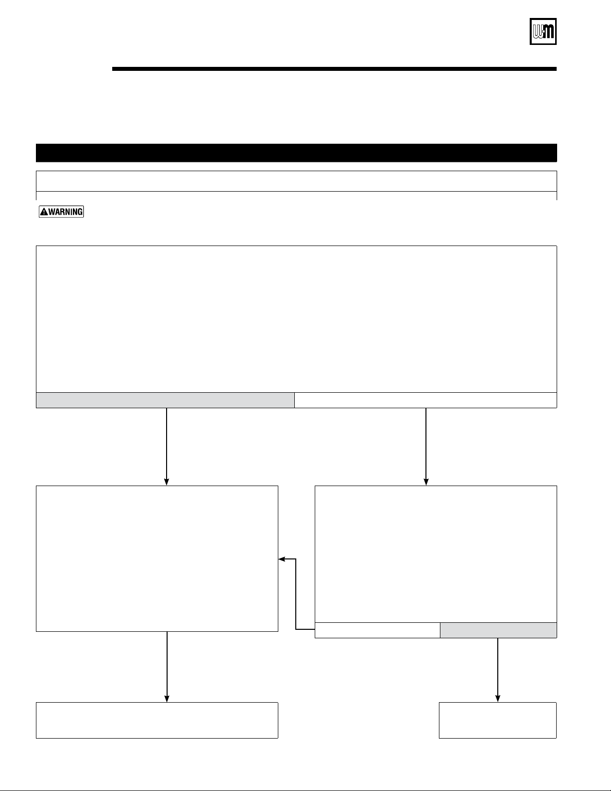
CHART 2 –– Spark-ignited pilot –– TSTAT CIRC & POWER lights flashing
–– Usually indicates 48 VAC on thermostat circuit (stray voltage) ––
Electrical shock hazard — Wherever you see
▲
TURN OFF POWER
▲
, follow the instructions. Failure to follow
instructions could result in severe personal injury, death or substantial property damage.
• Disconnect the two external wires connected to the boiler
thermostat leads (two black low voltage leads in J-box).
• Connect a voltmeter across these two incoming wires.
Close each thermostat, zone valve and relay in the external
circuit one at a time and check the voltmeter reading
across the wires.
• There should NEVER be a voltage reading.
• If a voltage does occur under any condition, check and
correct the external wiring. (This is a common problem
when using 3-wire zone valves).
• Once the external thermostat circuit wiring is checked and
corrected if necessary, reconnect the external thermostat
circuit wires to the boiler thermostat wires and allow the
boiler to cycle.
Did you nd a voltage across the two external thermostat circuit wires ?
Yes No
• If no voltage is found under any condition on the external
thermostat circuit, connect the two boiler thermostat
connection leads together (or jumper the boiler aquastat
T-T terminals).
• Turn off power to the boiler for 1 minute.
• Turn on power and allow boiler to cycle.
Do the TSTAT and POWER lights still ash ?
No Yes
• Replace control module.
• Retest.
•
Leave external boiler thermostat connection wires
disconnect from boiler.
• Troubleshoot the external thermostat circuit until you nd
the source of the stray voltage. (Pay close attention to
the wiring connections to 3-wire zone valves).
• Correct the problem and repeat the voltmeter test above,
verifying
there is no longer a voltage reading under any
condition in the external thermostat circuit.
Loading ...
Loading ...
Loading ...