Loading ...
Loading ...
Loading ...
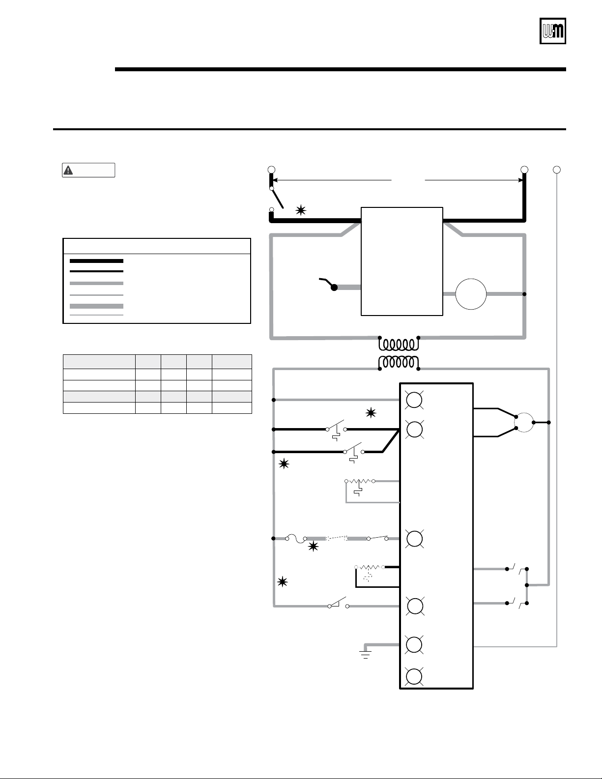
1. All wiring must be installed in accordance with:
A. U.S.A. —N.E.C. And any other national, state,
or local code requirements.
B. Canada —C.S.A. C22.1 C.E.C. Part 1 and
any other national, provincial, or local code
requirements.
2. Pilot lead wires are not field replaceable.
Replace pilot assembly if necessary.
3. If any of the original wire as supplied with the
appliance must be replaced, use minimum 105
°C wire or equivalent. Exception —wires to a
rollout TFE must be 200 °C or equivalent.
4. Thermostat anticipator setting (single zone) —
see Table G for anticipator setting, depending
on which gas valve is installed in boiler.
5. For multiple zoning, use either zone valves or
circulators. Refer to the component manufac-
turer's instructions and this manual for applica-
tion and wiring suggestions.
6. Refer to control component instructions
packed with the boiler for application informa-
tion.
7. Wire any additional limit controls (low water
cut-off, additional high limit, etc.) in series with
boiler rollout TFE and spill switch as shown.
Honeywell VR8204
Honeywell VR8304
White-Rodgers 36E
White-Rodgers 36C
*Terminals 2–4 are factory-jumpered on the
White-Rodgers 36C gas valve.
MV/PV
MV/PV
2
2–4 *
MV
MV
1
1
PV
PV
3
3
Table G: Gas valve terminals and anticipator settings
Gas valve
"A""B" "C"
Anticipator
amps
0.6
0.8
0.64
0.7
Electrical shock hazard — can
cause severe injuryor death.
Disconnect power before installing
or servicing.
WARNING
Legend for ladder wiring diagram
120 VAC factory wiring
High voltage spark ignition wiring
Low voltage factory wiring
Ground connectors
120 VAC field wiring
Low voltage field wiring
59374a+LWCO
SERVICE
SWITCH
THERMOSTAT
120 VAC
24 VAC
Control Module
LowVoltage Section
CONTROL
MODULE
120 VAC
SECTION
ROLLOUT
TFE
Additional
limits (note 7)
CIRCULATOR
PILOT GAS
VALVE
MAIN GAS
VALVE
TEMPERATURE
LWCO SENSOR
PILOT FLAME
SENSOR
PILOT
IGNITION
ELECTRODE
HIGH
VOLTAGE
HIGH
VOLTAGE
120 VAC
GndNeutralHot
See Table G
"A"
"C"
"B"
Power
Tstat–Circ
Limit
Damper
Flame
R
R
R
R
R
Outdoor Temperature
Sensor (if used)
SPILL
SWITCH
DAMPER END SWITCH
(INTERNAL TO DAMPER)
VENT
DAMPER
24 VAC
CALL
FOR HEAT
24 VAC
CONSTANT
LWCO
R
DHW (if used)
Part Number 550-142-300/0520
37
CGa Series 3 Gas-Fired Water Boiler — Boiler Manual
Figure 25b Ladder wiring diagram — Spark-ignited pilot system
Operation — spark-ignited pilot system (continued)9a
Loading ...
Loading ...
Loading ...