Loading ...
Loading ...
Loading ...
Part Number 550-142-300/0520
47
CGa Series 3 Gas-Fired Water Boiler — Boiler Manual
Service & maintenance – annual start-up (cont.)10b
❏ Cleaning boiler heating surfaces (continued)
6. Remove radiation plates hanging between sections.
7. Remove burners from base. Brush and vacuum burners to
remove all dust and lint. Verify that all burner ports are free
of debris.
8. Place newspapers in base of boiler to collect soot.
9. Clean between sections with wire flue brush.
10. Remove newspaper and soot. Vacuum or brush base and
surrounding area.
11. Reinstall radiation plates.
12. Replace collector box/transition assembly. Seal with sealant.
Obtain gas-tight seal to prevent flue gas spillage and carbon
monoxide emissions, resulting in severe personal injury or
death.
13. Replace insulation and jacket top panel.
14. Start up boiler following Section
6 of this manual and the
boiler Operating instructions (Section 9b). Excessive sooting
indicates improper gas combustion. If found, check for proper
combustion and make any necessary adjustments.
Before troubleshooting:
1. Have the following items:
a. Voltmeter that can check 120 VAC and 24 VAC.
b. Microammeter with a minimum scale range of
0-25.
c. Continuity checker.
d. U-tube manometer.
2. Check for 120 VAC (minimum 102 VAC to maximum
132 VAC) to boiler.
3. Make sure thermostat is calling for heat and contacts
(including appropriate zone controls) are closed. Check
for 24 VAC between thermostat wire nuts and ground.
Troubleshooting — components11a
Label all wires prior to disconnection when
servicing controls. Wiring errors can cause
improper and dangerous operation.
Never jumper (bypass) rollout thermal
fuse element or any other device except for
momentary testing as outlined in Trouble-
shooting Charts
. Severe personal injury,
death or substantial property damage can
result.
Burner access panel must be in position
during boiler operation to prevent mo-
mentary flame rollout on ignition of main
flame. Severe personal injury or substantial
property damage will result.
See pages 48 through 56 for additional
troubleshooting information.
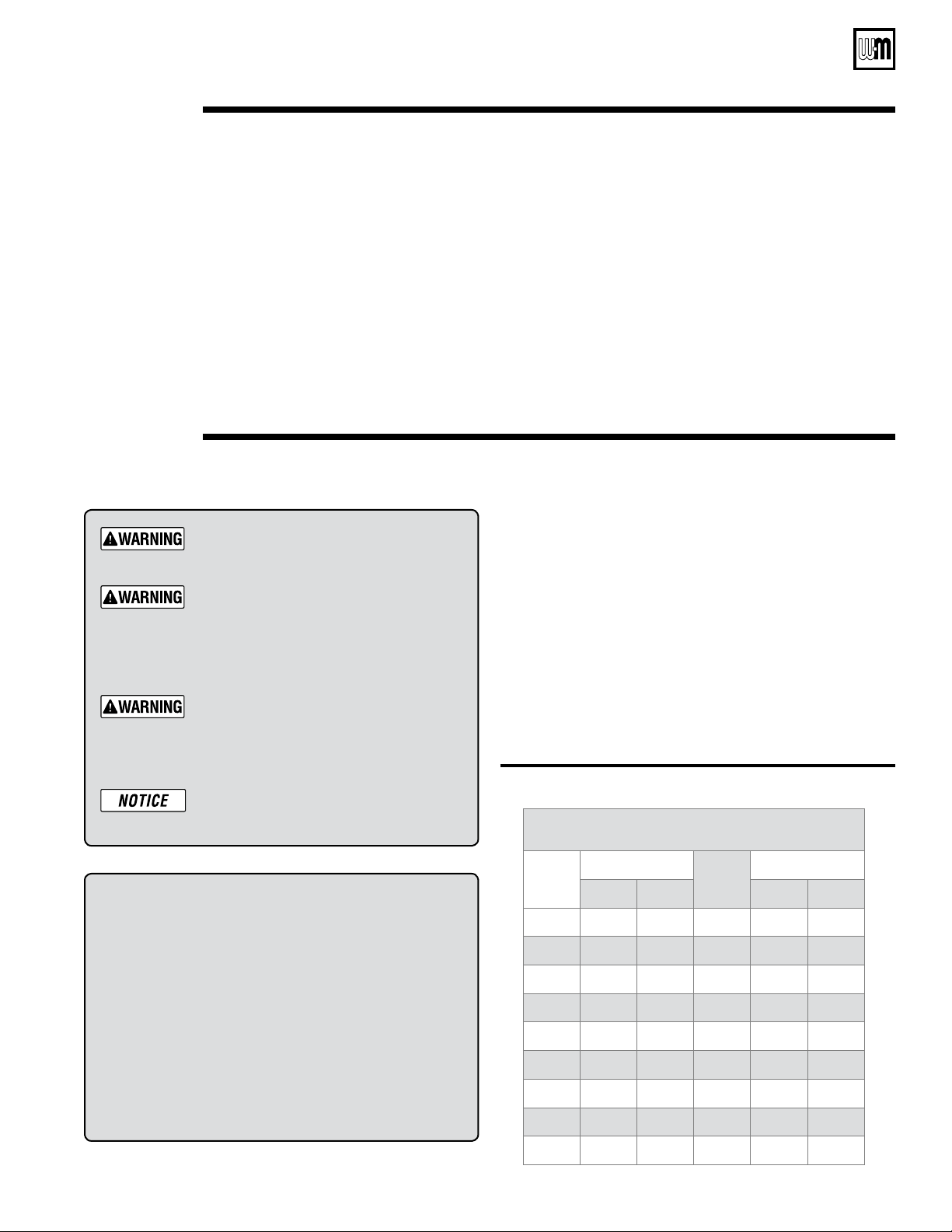
Sensor resistance values
Temp
(°F)
Sensor ohms
Temp
(°F)
Sensor ohms
Min Max Min Max
32
34265 37871
120
4517 4992
40
27834 30764
130
3698 4088
50
21630 23907
140
3043 3364
60
16944 18727
150
2517 2782
70
13372 14780
160
2091 2311
80
10629 11747
170
1744 1928
90
8504 9399
180
1461 1615
100
6847 7568
190
1229 1359
110
5545 6129
200
1038 1147
Temperature/LWCO sensor
1. The boiler temperature/LWCO sensor is a resistance-type
device.
2. The Table 7, below shows the correct value for the sensor at
various temperatures.
3. Use the resistance values at 32°F, 60°F, 70°F and 212°F to
measure the sensor resistance at known temperatures (ice
point, room temperature and sea level boiling point). For ice
point and boiling point, insert the sensor in water at that tem-
perature. Use an ohmmeter to read resistance value between
thermister # and thermistor common. See Figure 30, page 50,
for sensor plug details.
Table 7 Temperature/LWCO sensor resistance values
Loading ...
Loading ...
Loading ...