Loading ...
Loading ...
Loading ...
O
BL
BL
TSTAT
SENSORLWCO
TEST
OUTDOOR
COMM
BK
Y
C
BK
R
R
BK
G
R
Y
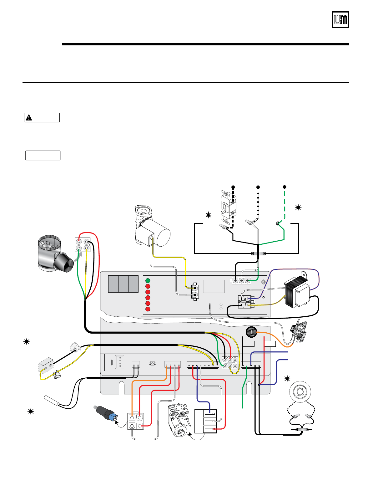
DO NOT connect directly from 3-wire zone valves to the T-T terminals on the
boiler. When using 3-wire zone valves, install an isolation relay. Connect the zone valve
end switch wires to the isolation relay coil. Connect the isolation relay contact across the
boilerT-T terminals. Failure to comply can result in damage to boiler components or
cause unreliable operation, resulting in possible severe property damage.
CAUTION
• The control module is polarity-sensitive to the incoming 120 VAC power. If polarity is
reversed, control will flash the light when powered and will not cycle boiler.POWER
•All contacts shown without power applied.
•Connector and status light locations/orientations may vary.
NOTICE
59374b +LWCO
Items not
provided
FIELD
WIRING
SERVICE
SWITCH
Junction box,
boiler left side
Jacket opening,
boiler left side
Black
White
Green
Ground
screw
Wire nuts
Black
Black
120 VAC—
Neutral
Hot
Gnd
W
BK
BR/Y
"C"
"A"
W
W
R
TRANSFORMER
TEMPERATURE/
LWCO SENSOR
PILOT
BURNER
GAS VALVE
CIRCULATOR
Terminal block
OFF
ON
W
Y
(Honeywell VR8204 shown)
80
60
70
80
70
60
THERMOSTAT
TRANSFORMER
POWER
CIRC
POWER
LIMIT
DAMPER
FLAME
LWCO
TSTAT/
CIRC
PILOT MAIN
FIELD
WIRING
O
BK
Y
ROLLOUT
TFE
Additional
limits,if used
(note 7)
Y
"B"
R
R
W
PK/BL
G
BK
W
To DHWAquastat
(if used)
To
Ground
Screw
BL
G
BK BK
OUTDOOR
TEMPERATURE
SENSOR
(if used)
SPILL SWITCH
Y
BK
1
2
3
4
VENT DAMPER
G
R
Part Number 550-142-300/0520
36
CGa Series 3 Gas-Fired Water Boiler — Boiler Manual
Operation — spark-ignited pilot system (continued)9a
Figure 25a Schematic wiring diagram — Spark-ignited pilot system
Loading ...
Loading ...
Loading ...