Loading ...
Loading ...
Loading ...
APPLICATION GUIDELINES | 55
Application Guidelines
Due to our policy of continuous product innovation, some specications may change without notication.
©
LG Electronics U.S.A., Inc., Englewood Cliffs, NJ. All rights reserved. “LG ” is a registered trademark of LG Corp.
PLACEMENT CONSIDERATIONS
Indoor Unit Clearance/Outdoor Unit Installation
General Mounting for Outdoor Units
Securely attach the outdoor unit to a condenser pad, base rails, or
another mounting platform that is securely anchored to the ground
or building structure. Attach the outdoor unit with a bolt and nut on
a concrete or rigid mount. See Figure 25. Refer to the applicable
installation manual and follow applicable local codes for clearance,
mounting, anchor and vibration attenuation requirements.
All referenced materials are to be eld-supplied. Images are not
to scale.
Mounting Platform
The underlying structure or foundation must be designed to support
the weight of the unit. Avoid placing the unit in a low lying area
where water may accumulate. When installing the outdoor unit on
the wall, or roof top, anchor the mounting base securely to account
for wind, earthquake or vibration.
Tie-Downs and Wind Restraints
The strength of the Duct-free Split Single Zone Inverter system
frame is adequate to be used with field-provided wind restraint
tie-downs. The overall tie-down configuration must be approved by a
local professional engineer.
Always refer to local code when designing a wind restraint system.
Snow and Ice Conditions
In climates that experience snow build-up, place the unit on a raised platform to ensure condenser airflow. The raised support platform must
be high enough to allow the unit to remain above possible snow drifts. Mount the unit on a field-provided snow stand at a minimum height
that is equal to the average annual snowfall plus 20 inches. Design the mounting base to prevent snow accumulation on the platform in front
or back of the unit case. If necessary, provide a field fabricated hood to keep snow and ice and/or drifting snow from accumulating on the coil
surfaces. Use inlet and discharge duct or hoods to prevent snow or rain from accumulating on the fan inlet and outlet guards. Best practice
prevents snow from accumulating on top of the unit. Consider tie-down requirements in case of high winds or where required by local codes.
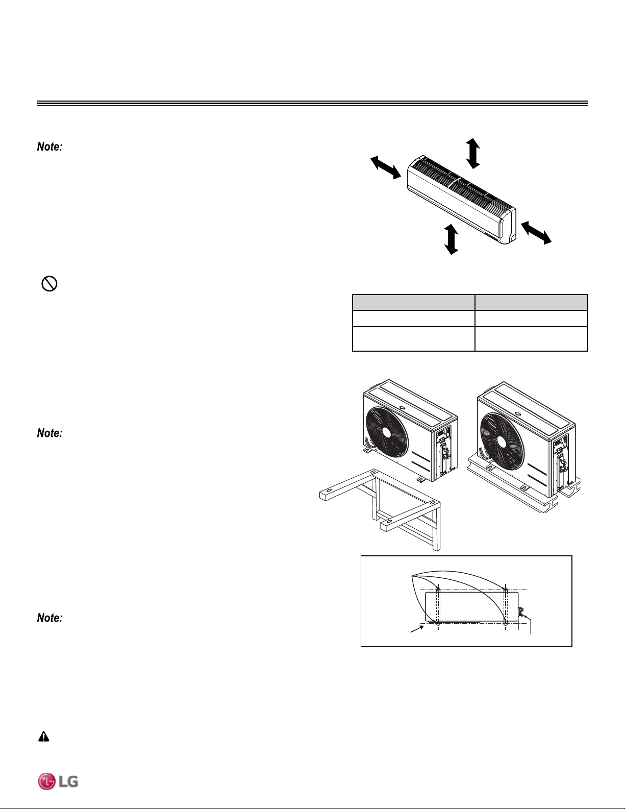
Figure 24: Single Zone Indoor Unit Clearance Requirements.
Bolt
Placement
& Anti-Vibration
Pad
Piping Connection
Top of Unit
Foundation
Indoor Unit Best Location
Follow recommended best practices when choosing an indoor location for the
single zone indoor unit.
• Use a metal detector to locate studs in the walls. Anchor unit following stud
location, to prevent damage to the wall.
• Clearance gap between any wall or enclosure and the left or right side of the
unit must be greater than 4 inches (Figure 24).
• Follow Table 11 for minimum clearance of indoor unit from the top of the unit
to the ceiling.
• Unit should be at least 6.5 feet from the oor for adequate clearance.
Minimum clearance
from ceiling - “A”
More than 4 inches
More than
4 inches
At least 6.5 feet from the floor
“A” Ceiling Clearance (inches) Indoor Unit Model(s)
5 LSN090HEV1, LSN120HEV1
8
LSN090HXV, LSN120HXV,
LSN180HEV1, LSN240HEV1
Table 11: Indoor Unit Ceiling Clearance.
Figure 25: Outdoor Unit Mounting Methods.
When deciding on a location to place the outdoor unit, be sure to choose an area where run-off from defrost will not accumulate and freeze on
sidewalks or driveways which may create unsafe conditions.
CAUTION
• Keep unit away from any indoor steam or excessive heat.
• No obstacles should be placed around unit.
• Condensation drain (leakage piping) should be routed away from the unit.
• Do not install near doorway.
Loading ...
Loading ...
Loading ...